


Mindray AS3000 Service Manual
AS
™
Datascope
Service Manual
ANESTHESIA DELIVERY SYSTEM

AS
™
Datascope
Service Manual
ANESTHESIA DELIVERY SYSTEM

AS3000™ is a U.S. trademark of Mindray DS USA, Inc.
Copyright © Mindray DS USA, Inc., 2008. All rights reserved. Contents of this publication may not be reproduced in any
form without permission of Mindray DS USA, Inc.
®
Krytox
is a U.S. registered trademark of E. I. du Pont de Nemours and Company
Selectatec
Glyptal
®
®
is a U.S. registered trademark of Glyptal, Inc.
Dräger Vapor
is a U.S. trademark of Datex Ohmeda
®
and plug-in system S-2000 are registered trademarks of Dräger Medical.
AS3000™ Service Manual 0070-10-0683

Table of Contents
Foreword.......................................................................................................................................................vii
Warnings, Cautions and Notes ........................................................................................................................vii
Warnings ......................................................................................................................................................vii
Cautions .......................................................................................................................................................viii
Notes ............................................................................................................................................................ ix
Theory of Operation .....................................................................................................1 - 1
Introduction................................................................................................................................................ 1 - 1
Microprocessor-controlled Ventilator.............................................................................................................. 1 - 2
Components............................................................................................................................................... 1 - 3
Front View .......................................................................................................................................... 1 - 3
Side View........................................................................................................................................... 1 - 5
Rear View........................................................................................................................................... 1 - 7
Other components (not identified in graphics) ......................................................................................... 1 - 8
Breathing System................................................................................................................................. 1 - 9
The Ventilator Unit ............................................................................................................................... 1 - 9
Adjustable Alarms ............................................................................................................................. 1 - 10
Compliance Compensation................................................................................................................. 1 - 10
Electrical Supply ....................................................................................................................................... 1 - 11
Electrical components......................................................................................................................... 1 - 11
Ventilator Control and Drive....................................................................................................................... 1 - 12
BDU (Basic Digital Unit)...................................................................................................................... 1 - 12
Amplifier Board ........................................................................................................................ 1 - 14
Drive Gas Pressure Sensor Board ................................................................................................ 1 - 19
PAW Pressure Sensor Board....................................................................................................... 1 - 20
Breathing System Heater ............................................................................................................ 1 - 21
Sensor Board............................................................................................................................ 1 - 23
Power Management........................................................................................................................... 1 - 26
Battery ............................................................................................................................................. 1 - 28
Power Supply.................................................................................................................................... 1 - 28
Anesthesia System Components .................................................................................................................. 1 - 29
Auxiliary Outlets................................................................................................................................ 1 - 29
Absorber Heater Wire Board .............................................................................................................. 1 - 29
Work Light Board .............................................................................................................................. 1 - 29
Ventilator UI ............................................................................................................................................. 1 - 31
Keyboard Board................................................................................................................................ 1 - 31
Display............................................................................................................................................. 1 - 34
Communication Interface / RS232 Isolate Board ...................................................................................1 - 35
Fuses ............................................................................................................................................... 1 - 35
Ventilator Pneumatic - O
Ventilator pneumatic drive .................................................................................................................. 1 - 36
Drive Pressure-High pressure regulator ................................................................................................. 1 - 36
Gas Box Assembly............................................................................................................................. 1 - 36
Tube color coding.............................................................................................................................. 1 - 36
The Breathing System ................................................................................................................................ 1 - 37
CMV mode, inspiration ...................................................................................................................... 1 - 37
CMV mode, expiration....................................................................................................................... 1 - 37
Manual mode, inspiration................................................................................................................... 1 - 38
Manual mode, expiration ................................................................................................................... 1 - 38
Pneumatic PEEP ................................................................................................................................. 1 - 39
Ventilator in Standby.......................................................................................................................... 1 - 39
Breathing System Components ............................................................................................................ 1 - 39
Ventilation Bellows System.......................................................................................................... 1 - 39
Drive Gas ........................................................................................................... 1 - 36
2
AS3000™ Service Manual 0070-10-0683 i

Table of Contents
Manual Breathing Bag............................................................................................................... 1 - 39
Absorber .......................................................................................................................... 1 - 39
CO
2
Inspiratory and Expiratory Valves................................................................................................ 1 - 39
APL (Airway Pressure Limiting) valve ............................................................................................ 1 - 39
Installation Guide .........................................................................................................2 - 1
Delivery of The New Anesthesia Machine ...................................................................................................... 2 - 1
Assembly ................................................................................................................................................... 2 - 2
Unpacking.......................................................................................................................................... 2 - 2
Breathing System and Breathing System Accessories ................................................................................ 2 - 2
Attaching the Mounting Arms and User Interface............................................................................. 2 - 3
Breathing System Connections ...................................................................................................... 2 - 3
Anesthesia System Connections..................................................................................................... 2 - 3
Tank Wrench and Pre-operation Checklist............................................................................................... 2 - 4
Patient Suction Regulator and Arm......................................................................................................... 2 - 4
Suction Canister Bracket....................................................................................................................... 2 - 4
Utility Tray, Monitor Mounting Arm with Utility Hook(s)............................................................................. 2 - 4
Vaporizers.......................................................................................................................................... 2 - 4
High Pressure Hoses ............................................................................................................................ 2 - 5
Emergency Cylinder(s) ......................................................................................................................... 2 - 5
Breathing Circuit, CO
Absorbent, and Liquid Vaporizer Agent ................................................................ 2 - 5
2
Monitoring Products - Mounting and Electrical Connection........................................................................2 - 6
Agent Monitor Waste Gas Scavenging .................................................................................................. 2 - 6
Oxygen Sensor Calibration .................................................................................................................. 2 - 6
Installation Checkout Procedure .................................................................................................................... 2 - 8
Repair Information ....................................................................................................... 3 - 1
Introduction................................................................................................................................................ 3 - 1
Warnings and Cautions............................................................................................................................... 3 - 2
Warnings ........................................................................................................................................... 3 - 2
Cautions............................................................................................................................................. 3 - 2
Troubleshooting Guidelines .......................................................................................................................... 3 - 2
Special Tools Required ................................................................................................................................ 3 - 3
Troubleshooting Chart ................................................................................................................................. 3 - 4
Common Symptoms and Corrective Actions for Field Service Technicians ................................................... 3 - 4
Leak Troubleshooting................................................................................................................................. 3 - 11
Test Pneumatics ........................................................................................................................................ 3 - 12
Leak Test - Manual Ventilation Test....................................................................................................... 3 - 12
Safety Valve Test ............................................................................................................................... 3 - 13
Leak Test - Automatic Ventilation Test.................................................................................................... 3 - 14
Compliance Test................................................................................................................................ 3 - 15
Pneumatic Hose and Wiring Diagrams ........................................................................................................ 3 - 16
Pneumatic Hose Labeling.................................................................................................................... 3 - 16
Sampling Pipeline Module Interface Labeling ........................................................................................ 3 - 17
Electrical Cable Labeling .................................................................................................................... 3 - 18
Replacement Parts and Accessories ...............................................................................4 - 1
Introduction................................................................................................................................................ 4 - 1
Available Replacement Parts and Sub-Assemblies ........................................................................................... 4 - 1
Exchange Program .............................................................................................................................. 4 - 1
Replacement Parts Pricing Information .................................................................................................... 4 - 1
Ordering Information ........................................................................................................................... 4 - 2
Isometric Drawings...................................................................................................................................... 4 - 3
Chassis .............................................................................................................................................. 4 - 3
Chassis Parts List ......................................................................................................................... 4 - 5
ii 0070-10-0683 AS3000™ Service Manual

Table of Contents
Breathing System................................................................................................................................. 4 - 6
Breathing System Parts List.......................................................................................................... 4 - 11
Electric Box....................................................................................................................................... 4 - 12
Electric Box Parts List.................................................................................................................. 4 - 12
Gas Circuit Box................................................................................................................................. 4 - 13
Gas Circuit Box Parts List............................................................................................................ 4 - 13
User Interface.................................................................................................................................... 4 - 14
User Interface Parts List............................................................................................................... 4 - 15
Flowmeter......................................................................................................................................... 4 - 16
Flowmeter Parts List.................................................................................................................... 4 - 16
Calibration ...................................................................................................................5 - 1
Introduction................................................................................................................................................ 5 - 1
Calibration Warnings, Precautions, and Notes............................................................................................... 5 - 2
Warnings ........................................................................................................................................... 5 - 2
Cautions............................................................................................................................................. 5 - 2
Notes................................................................................................................................................. 5 - 3
General Guidelines..................................................................................................................................... 5 - 4
Test Equipment and Special Tools Required.................................................................................................... 5 - 4
Calibration Procedures ................................................................................................................................ 5 - 4
Oxygen Sensor Calibration .................................................................................................................. 5 - 4
Proportional Valve Regulator Calibration ................................................................................................ 5 - 6
Flow Sensor Calibration ....................................................................................................................... 5 - 7
Flow Valve Calibration......................................................................................................................... 5 - 9
Paw Sensor....................................................................................................................................... 5 - 10
PEEP Valve ....................................................................................................................................... 5 - 11
Flow Meter ....................................................................................................................................... 5 - 12
Leakage detection.............................................................................................................................. 5 - 13
Startup leakage detection........................................................................................................... 5 - 13
APL Valve leakage detection....................................................................................................... 5 - 13
Safety Valve leakage detection ................................................................................................... 5 - 13
Breathing System leakage detection............................................................................................. 5 - 13
Compliance detection ........................................................................................................................ 5 - 13
Periodic Maintenance.................................................................................................... 6 - 1
Maintenance Schedule ................................................................................................................................ 6 - 1
Periodic Maintenance Consumable Parts Kits.................................................................................................. 6 - 1
Periodic Maintenance Schedule of Service Activities........................................................................................ 6 - 2
Visual Inspection Checklist ........................................................................................................................... 6 - 2
Replacement of Consumable Parts................................................................................................................. 6 - 3
Check Valve Cleaning................................................................................................................................. 6 - 4
Tools and Materials ............................................................................................................................. 6 - 4
Cleaning Procedure ............................................................................................................................. 6 - 5
Battery Maintenance and Replacement ........................................................................................................ 6 - 13
Battery Maintenance .......................................................................................................................... 6 - 13
Battery Replacement .......................................................................................................................... 6 - 13
Functional Tests ........................................................................................................................................ 6 - 13
Test Equipment and Special Tools Required........................................................................................... 6 - 13
Pressure Regulator Checks .................................................................................................................. 6 - 14
Proportional Valve Regulator ...................................................................................................... 6 - 14
Gas Delivery System Tests................................................................................................................... 6 - 14
Flush Verification ................................................................................................................. 6 - 14
O
2
O Ratio System ............................................................................................................... 6 - 15
O
2:N2
Start-Up Tests .................................................................................................................................... 6 - 15
AS3000™ Service Manual 0070-10-0683 iii

Table of Contents
System Self Test......................................................................................................................... 6 - 15
Leak/Safety Valve Test............................................................................................................... 6 - 15
Leak Test .................................................................................................................................. 6 - 17
Compliance Test ....................................................................................................................... 6 - 20
Manual Leak Test ...................................................................................................................... 6 - 21
Oxygen Sensor Calibration ........................................................................................................ 6 - 22
Pneumatic Leak Tests.......................................................................................................................... 6 - 24
O Cylinder Leak Test ............................................................................................................. 6 - 24
N
2
Cylinder Leak Test................................................................................................................ 6 - 24
O
2
AIR Cylinder Leak Test ............................................................................................................... 6 - 24
Line Supply Check Valves Test .................................................................................................... 6 - 24
O Line Pressure Leak Test ....................................................................................................... 6 - 25
N
2
Line Pressure Leak Test.......................................................................................................... 6 - 25
O
2
AIR Line Pressure Leak Test ......................................................................................................... 6 - 25
Cylinder Supply Check Valves Test .............................................................................................. 6 - 25
Breathing System Checks.................................................................................................................... 6 - 26
Waste Gas Scavenger Test (if available) ...................................................................................... 6 - 26
Internal Gas Connections Test ..................................................................................................... 6 - 26
Drive Gas Pressure Loss Alarm, N
O Cutoff Test ........................................................................... 6 - 26
2
Performance Verification .................................................................................................................... 6 - 27
Standby Mode Ventilation Test.................................................................................................... 6 - 27
Manual Mode Ventilation Test .................................................................................................... 6 - 27
APNEA Alarm Test .................................................................................................................... 6 - 27
Alarm MUTE Test....................................................................................................................... 6 - 27
CMV Adult Ventilation Mode Test................................................................................................ 6 - 28
CMV Child Ventilation Mode Test................................................................................................ 6 - 29
Airway Disconnect Alarm Test..................................................................................................... 6 - 29
PCV Adult Ventilation Mode Test ................................................................................................. 6 - 30
Pressure Support (PS) Ventilation Mode Test.................................................................................. 6 - 31
Alarms and Failsafe Functions ............................................................................................................. 6 - 32
Set Up ..................................................................................................................................... 6 - 32
Low FiO
High FiO
Alarm Test.................................................................................................................. 6 - 32
2
Alarm Test ................................................................................................................ 6 - 33
2
Peak Pressure Alarms Test .......................................................................................................... 6 - 33
Minute Volume Alarm Test.......................................................................................................... 6 - 34
Miscellaneous Tests............................................................................................................................ 6 - 34
Test the Line Voltage Alarm ........................................................................................................ 6 - 34
Wheel Brakes Test..................................................................................................................... 6 - 34
Work Light Test ......................................................................................................................... 6 - 34
Auxiliary Flowmeter................................................................................................................... 6 - 35
Patient Suction Regulator (if available) ......................................................................................... 6 - 35
Vaporizers........................................................................................................................................ 6 - 35
Vaporizer Interlock Test.............................................................................................................. 6 - 35
Vaporizer Accuracy Test ............................................................................................................ 6 - 36
Vaporizer Leak Test ................................................................................................................... 6 - 36
Dräger Vapor 2000 Operating Instructions ARRB-F001 ................................................................. 6 - 37
Electrical Tests................................................................................................................................... 6 - 38
Convenience AC Outlets Test...................................................................................................... 6 - 38
Electrical Safety Inspection Test ................................................................................................... 6 - 38
AS3000 Installation Checklist ............................................................................................................. 6 - 38
Cleaning.................................................................................................................................................. 6 - 39
Cleaning and Disinfecting the AS3000 ................................................................................................ 6 - 39
iv 0070-10-0683 AS3000™ Service Manual

Table of Contents
Cleaning and Sterilizing the Breathing System and Components.............................................................. 6 - 39
Preoperative Checklist ............................................................................................................................... 6 - 39
Phone Numbers and How To Get Assistance................................................................................................ 6 - 47
Warranty ..................................................................................................................... 7 - 1
Warranty Statements................................................................................................................................... 7 - 1
Disclaimers ................................................................................................................................................ 7 - 2
Product Improvements .......................................................................................................................... 7 - 2
Manufacturer’s Responsibility ....................................................................................................................... 7 - 2
AS3000™ Service Manual 0070-10-0683 v

Table of Contents
This page intentionally left blank.
vi 0070-10-0683 AS3000™ Service Manual

Foreword Introduction
Foreword
This Service Manual is intended as a guide for technically qualified personnel performing
repair and calibration procedures.
Warnings, Cautions and Notes
Please read and adhere to all warnings, cautions and notes listed here and in the
appropriate areas throughout this manual.
A WARNING is provided to alert the user to potential serious outcomes (death, injury, or
serious adverse events) to the patient or the user.
A CAUTION is provided to alert the user to use special care necessary for the safe and
effective use of the device. They may include actions to be taken to avoid effects on patients
or users that may not be potentially life threatening or result in serious injury, but about which
the user should be aware. Cautions are also provided to alert the user to adverse effects on
this device of use or misuse and the care necessary to avoid such effects.
A NOTE is provided when additional general information is applicable.
Warnings
WARNING: Whenever using anesthetic gases, nitrous oxide, oxygen, or
WARNING: For continued protection against fire hazard, replace all
WARNING: In order to prevent an electric shock, the machine
WARNING: Remove all accessory equipment from the shelf before
WARNING: Possible explosion hazard. Do not operate machine near
WARNING: The use of anti-static or electrically conductive respiration
any hospital gas always follow the appropriate agent
evacuation/collection procedures. Use the hospital gas
evacuation system.
fuses with the specified type and rating.
(protection class I) may only be connected to a correctly
grounded mains connection (socket outlet with grounding
contact).
moving the anesthesia machine over bumps or on any
inclined surface. Heavy top loading can cause the machine
to tip over causing injury.
flammable anesthetic agents or other flammable
substances. Do not use flammable anesthetic agents (i.e.,
ether or cyclopropane.)
tubes, when utilizing high frequency electric surgery
equipment, may cause burns and is therefore not
recommended in any application of this machine.
WARNING: Possible electric shock hazard. The machine may only be
opened by authorized service personnel.
AS3000™ Service Manual 0070-10-0683 vii

Introduction Cautions
WARNING: Compressed gasses are considered Dangerous Goods/
WARNING: Avoid exposure to respiratory gases by always directing
Hazardous Materials per I.A.T.A. and D.O.T. regulations. It is
a violation of federal and international law to offer any
package or over pack of dangerous goods for
transportation without the package being appropriately
identified, packed, marked, classified, labeled and
documented according to D.O.T. and I.A.T.A. regulations.
Please refer to the applicable I.A.T.A. Dangerous Goods
Regulations and /or the Code of Federal Regulations 49
(Transportation, Parts 171-180) for further information.
the fresh gas flow from the fresh gas outlet to the waste gas
scavenger.
Cautions
CAUTION: This device uses high pressure compressed gas. When
attaching or disconnecting backup gas cylinders, always
turn the cylinder valves slowly. Use the AS3000 flow meters
to bleed down the pressure, watching the cylinder gauge
indicate the depleting cylinder pressure, before
disconnecting the cylinder from the yoke. Always open and
close cylinder valves fully.
CAUTION: This device operates using compressed gas at high
pressures from the hospital central supply. When connecting
gas supply lines attach the hose connection to the machine
before connecting the quick disconnect fitting to the hospital
source. Disconnect the supply hose from the hospital source
connection prior to disconnecting it from the AS3000 gas
connection fittings.
CAUTION: Refer to the “Periodic Maintenance Schedule of Service
Activities” on page 6-2, in the Periodic Maintenance section
for assistance when performing scheduled periodic
maintenance.
CAUTION: Do not leave gas cylinder valves open if the pipeline supply
is in use and the system master switch is turned to 'ON'. If
used simultaneously, cylinder supplies could be depleted,
leaving an insufficient reserve supply in the event of
pipeline failure.
CAUTION: Use cleaning agent sparingly. Excess fluid could enter the
machine, causing damage.
CAUTION: This machine must only be operated by trained, skilled
medical staff.
CAUTION: Perform the electrical safety inspection as the last step after
completing a repair or after routine maintenance. Perform
this inspection with all covers, panels, and screws installed.
CAUTION: After changing the CO
CAUTION: Only Selectatec
CAUTION: After each exchange of a vaporizer, carry out a system Leak
test.
™
System may be used with the AS3000 unit.
test.
absorbent, carry out a system leak
2
compatible vaporizers with Interlock-
viii 0070-10-0683 AS3000™ Service Manual

Notes Introduction
CAUTION: The bellows dome cannot be autoclaved.
CAUTION: Do not clean the machine while it is on and/or plugged in.
CAUTION: Pressing “Quit” at any time during the procedure will cancel
the session's settings and reload the previously-stored
calibration coefficients.
CAUTION: Depleted soda lime changes color. Replace the soda lime if
approximately 2/3 of the absorber content is discolored.
absorbent can be safely changed without stopping
CO
2
mechanical ventilation.
Notes
NOTE: Unauthorized servicing may void the remainder of the
warranty. Check with the factory or with a local authorized
distributor to determine the warranty status of a particular
instrument.
AS3000™ Service Manual 0070-10-0683 ix

Introduction Notes
This page intentionally left blank.
x 0070-10-0683 AS3000™ Service Manual

1.0
Theory of Operation
1.1 Introduction
The AS3000 is a continuous flow anesthesia system which offers manual or automatic
ventilation, easily adjustable fresh gas delivery, anesthetic agent delivery, ventilation
monitoring, convenient ergonomics, and state-of-the-art safety systems. The components of the
AS3000 Anesthesia System are described this chapter.
AS3000™ Service Manual 0070-10-0683 1 - 1

Microprocessor-controlled Ventilator Theory of Operation
Gas Inlet
Block
N20
AIR
O2
Breathing
System
Ventilator
Pressure
Switch
Pressure
Regulator
Pressure
Regulator
Pressure
Regulator
Ratio•
Controller
N20•
Cuttoff
Flow
Tubes
Cylinder
Cylinder
Cylinder
Inlet Filter
Inlet Filter
Inlet Filter
O2
Flow
Meter
O2
Outlet
AIR•
Flow
Meter
Patient
Vaporizer
O2
Flush
Pressure
Regulator
Proportional
Valve
Solenoid
Valve
Fresh Gas
PEEP
Valve
Exhaust
Valve
APLValve
AGSS
Electronic
Control
Reversing
Valve
O2 Sensor
Insp.Valve
Absorber
Canister
Exp.Valve
Breathing Bag
OOO
P
P
P
P
P
P
P
Exp. Flow
Sensor
Insp. Flow
Sensor
Fresh Gas
Flow Sensor
V
Bellows
Vaporizer
1.2 Microprocessor-controlled Ventilator
The Microprocessor-controlled ventilator, with its dedicated Breathing System, allows timecontrolled, pressure limited, constant volume ventilation for all patient groups within a tidal
volume range of 40 mL (4 kg infant) to 1400 mL (large adult).
Time-controlled, pressure limited, and compliance compensated constant volume ventilation
is provided through the Controlled Mandatory Ventilation (CMV) mode. The CMV mode
delivers a viable ventilation method for complicated lung conditions. The ventilator also
provides time-controlled, volume dependant ventilation, targeting a set (adjustable) target
pressure provided through the Pressure Controlled Ventilation (PCV) mode. Automatic and
comprehensive system startup tests and alarm management systems ensure controlled
ventilation conditions in every mode of operation.
The durable and ergonomically designed user interface and Navigator
™
Knob enables easy
operation. The display provides the selected ventilation modes (CMV, PCV, PS and SIMV)
and the following values: Tidal Volume, Peak Pressure, Mean Pressure, FiO
, Breath Rate, I:E
2
Ratio, PEEP, Plateau Pressure, Alarm limits, and real-time Airway Pressure and flow
waveform.
1 - 2 0070-10-0683 AS3000™ Service Manual
FIGURE 1-1 The AS3000 Pneumatic System
Theory of Operation Components
4
5
6
7
8
9
2
1
10
11
3
1.3 Components
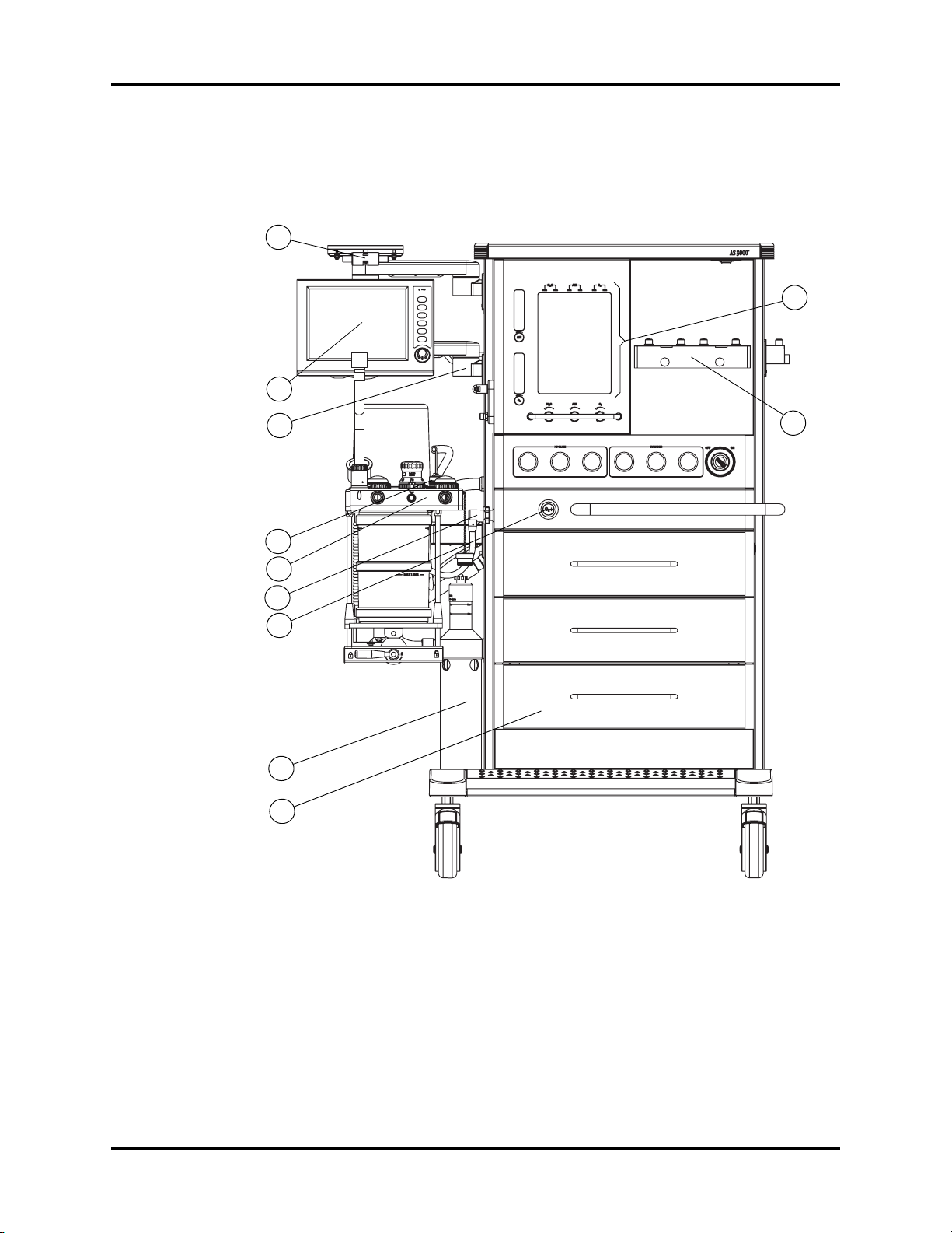
1.3.1 Front View
FIGURE 1-2 AS3000 Front View
1. Monitor Arm
The Monitor Arm provides support for a bedside monitor. It can easily rotate for more
convenient viewing.
2. User Interface
The display of the user Interface provides waveforms, numeric data and menu tabs. The keys
and Navigator Knob enable the user to power up the system, silence alarms, access menu
AS3000™ Service Manual 0070-10-0683 1 - 3
tabs, and switch between manual and mechanic ventilation.

Components Theory of Operation
3. UI Arm
The UI Arm provides support for the user interface assembly. It can easily rotate for more
convenient viewing.
4. Oxygen Sensor
The Oxygen Sensor monitors the oxygen concentration of the inspired gas of the Breathing
System.
5. Breathing System
The Breathing System’s main function is to store anesthetic gas, oxygen, and air; vent exhaust
gas; and absorb carbon dioxide. It connects directly to the respiratory passage to help
complete the breathing process.
6. CGO (Common Gas Outlet) Subassembly
Mixed gas composed of O
, AIR, N2O, and anesthetic agent connects to the patient's
2
Breathing System via a flexible tube from the CGO Subassembly.
7. O2 Flush Valve
The O2 Flush Valve is located on the front of the AS3000. The supplied gas does not pass
the flowmeter and vaporizer. It is directly sent to the fresh gas outlet. Press this button to
supply gas (35 - 50 L/min). Release this switch to automatically close the gas supply.
8. AGSS (Anesthetic Gas Scavenging System)
The AGSS (Anesthetic Gas Scavenging System) reclaims exhausted gas generated during
anesthesia.
9. Drawer Subassembly
The AS3000 has three drawers for storage, which can be locked and fixed through the
uppermost drawer lock.
10. Vaporizer Mounting Manifold
The Vaporizer Mounting Manifold provides support for up to two Selectatec
®
compatible
anesthetic vaporizers.
11. Flowmeter
The Flowmeter displays gas flow values for N2O, O2, AIR, Auxiliary O2, and Auxiliary AIR.
It consists of coarse and fine flow tubes used to accurately measure gas flow with additional
flow tubes to measure auxiliary O
and AIR gas flow.
2
Flow tube measurement values:
GAS FINE FLOW TUBE
O 0 - 1 L/min 1 - 12 L/min 1 - 10 L/min N/A
N
2
O
2
0 - 1 L/min 1 - 10 L/min 1 - 10 L/min 0 - 15 L/min
COARSE FLOW TUBE
-01 UNITS -02 UNITS AUXILIARY FLOW TUBE
AIR 0 - 1 L/min 1 - 15 L/min 1 - 12 L/min 0 - 15 L/min
1 - 4 0070-10-0683 AS3000™ Service Manual
Theory of Operation Components
12
13
14
15
16
17
18
19
20
21
22
23
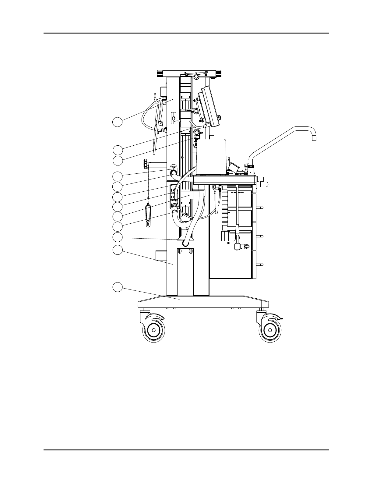
1.3.2 Side View
FIGURE 1-3 AS3000 Side View
12. Upper Mainframe Subassembly
The Upper Mainframe Subassembly provides support for the pressure gauges, the Flowmeter,
the gas box assembly, the mains supply assembly, and the YOKE assembly.
13. User Interface Cable
The User Interface Cable provides signal transmission between the User Interface and the
main unit.
AS3000™ Service Manual 0070-10-0683 1 - 5

Components Theory of Operation
14. Auxiliary Gas Outlet Assembly
The Auxiliary Gas Outlet Assembly provides the patient with auxiliary oxygen and air mixtures
(of different concentrations). It also contains an O
connection for use with other equipment.
2
15. Breathing System Interface
The Breathing System Interface provides a connection interface for gas signal acquisition
between the Breathing System and gas circuit.
16. Breathing System Pneumatic Hose
The Breathing System Pneumatic Hose provides multiple connections including: PEEP control,
Auto/Manual control, and four pressure sampling connections between the Breathing System
and mainframe.
17. O
Sensor Cable
2
The O2 Sensor Cable provides a connection between the oxygen sensor component in the Breathing
System and the oxygen concentration signal acquisition port on outlet module of the mainframe.
18. Breathing System Interface
The Breathing System Interface provides the main unit with an interface for connection with
drive gas, heating system and the oxygen concentration sensor of the Breathing System.
19. The Breathing System Support Arm
The Breathing System Support Arm provides connection between the Breathing System and
the mainframe, in order to support the Breathing System.
20. Heater Wire
The Heater Wire provides connection to the heating system of the Breathing System. By
heating the Breathing System during anesthesia, accumulation of water in the Breathing
System is minimized. It also provides comfortable gas to the patient.
21. AGSS Transfer Hose
The AGSS Transfer Hose provides pipeline connection between the exhaust gas outlet of the
Breathing System and the AGSS evacuation system.
22. Lower Mainframe Assembly
The Lower Mainframe Assembly provides support for the drawer subassembly, outlet module,
CGO subassembly, O
flush valve and the electric box. Together with the Upper Mainframe
2
Subassembly and Base Assembly, forms the mainframe of the machine.
23. Base Assembly
The Base Assembly provides support to the whole machine. The four casters provide
movement for the machine in any direction. The front casters have a locking function.
1 - 6 0070-10-0683 AS3000™ Service Manual
Theory of Operation Components
24
25
26
27
28
29
30
31
32
33
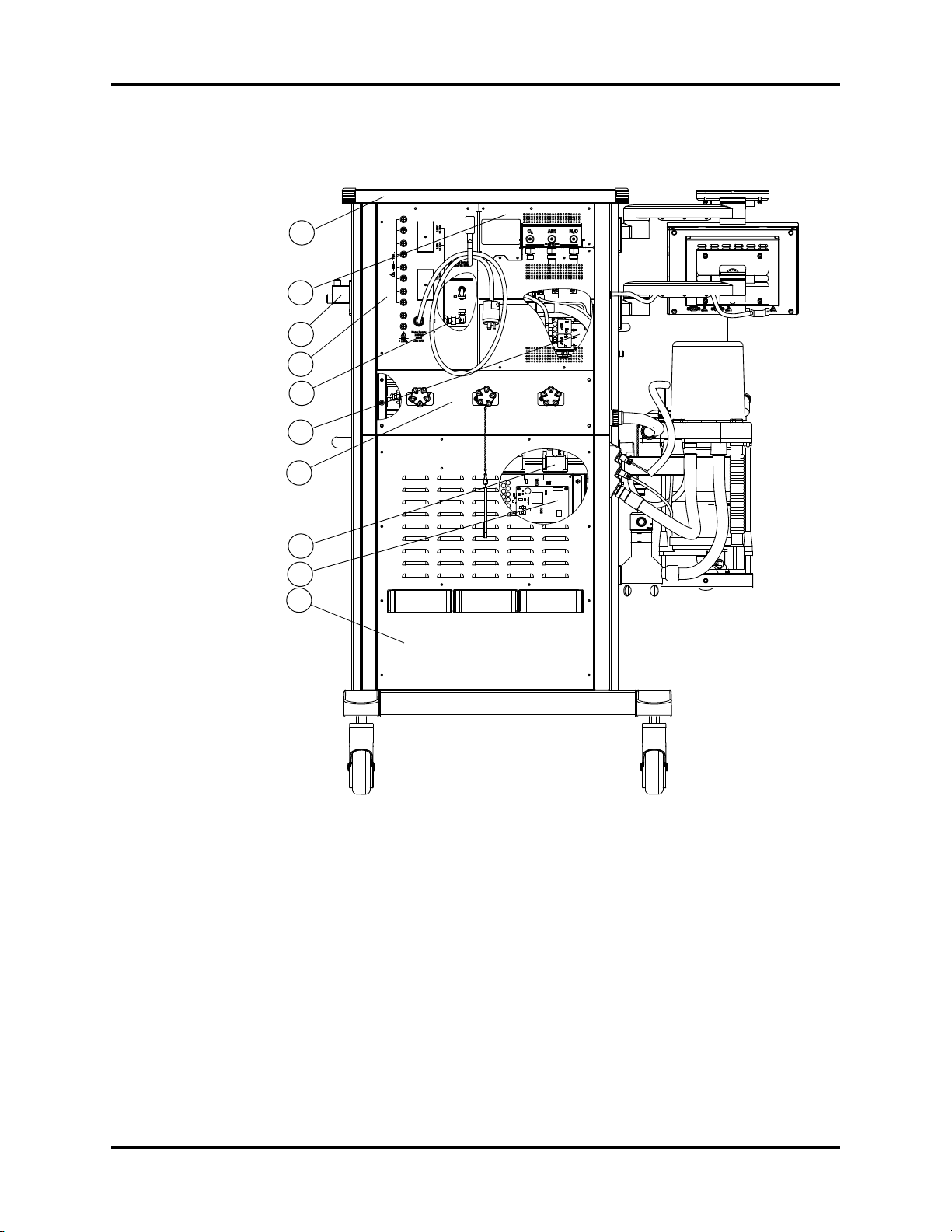
1.3.3 Rear View
FIGURE 1-4 AS3000 Rear View
24. Top Shelf Assembly
The Top shelf Assembly includes the work light and its switch. It also serves as a storage
area.
25. Gas Input Assembly
The Gas Input Assembly allows gas in the pipeline and backup gas cylinder to enter the
AS3000 for regulation. The Pressure regulator reduces pressure to 36 psi (250 kPa). The
O
operated valve can open allowing N2O to enter the flowmeter only when O2 pressure is
2
above 7.3 psi (50 kPa). Otherwise, N2O cannot enter the gas circuit. The pressure switch
generates a signal when the input pressure is below 29 psi (200 kPa), and the system will
provide an audible alarm.
AS3000™ Service Manual 0070-10-0683 1 - 7

Components Theory of Operation
26. Vaporizer Storage Mount
The Vaporizer Storage Mount provides the AS3000 with auxiliary placement for a
vaporizer.
27. Mains Supply Assembly
The Mains Supply Assembly attaches the AS3000 to an external AC wall outlet. It also
supplies power throughout the unit.
28. Electronic Flowmeter Assembly
The Electronic Flowmeter Assembly provides fresh gas flow measurement for the AS3000.
29. Gas Box Assembly
The Gas Box Assembly provides drive gas to the Breathing System and includes a safety
valve to insure that pressure stays below 85 cmH
O. It also contains the PEEP valve, and the
2
differential pressure sensors.
30. YOKE Assembly
The YOKE Assembly provides connection for three backup gas cylinders. The pressure
regulator for the backup gas cylinder reduces the pressure of a high pressure gas cylinder
down to 43.5 psi (300 kPa).
31. AMP Cables
The AMP Cables provide signal transmission between the electric box and gas circuit box.
32. Electric Box Assembly
The Electric Box Assembly provides, and distributes power to the AS3000.
33. Rear Panel Assembly
The Rear Panel Assembly protects, and provides heat dissipation for the electric box and
auxiliary support for the backup gas cylinder.
1.3.4 Other components (not identified in graphics)
34. Inspiratory and Expiratory Valves
The Inspiratory and Expiratory Valves are unidirectional valves that allow air to flow in only
one direction.
35. Absorber Canister
The AS3000 uses two Absorber Canisters which can contain 1500 mL of soda lime each.
They can be used for 6 - 8 hours each if full. Water generated from the reaction with CO
drained from a valve on the lower side of the canister.
36. APL (Airway Pressure Limiting) Valve
The APL Valve is used for limiting maximum airway pressure during manual ventilation. The
adjustable range of the APL is 0 - 70 cmH
O.
2
is
2
1 - 8 0070-10-0683 AS3000™ Service Manual

Theory of Operation Components
37. Bellows Assembly
The AS3000 employs ascending ventilation bellows, in which mixed gas is stored. Drive
gas supplied by the ventilator forces the bellows to descend sending mixed gas into the
inspiratory passage of patient's airway. If a patient's airway suffers from gas leakage, the
bellows will collapse, informing the operator of a possible problem. A tidal volume scale is
provided on the transparent dome, through which a patient's tidal volume can be estimated.
38. Pressure-relief Valve
The Pressure-relief Valve is located at the base of the bellows. When end-expiration airway
pressure reaches 1 - 3 cmH
expelled.
39. Exhaust Gas Outlet
The Exhaust Gas Outlet is located on the lower part of the Breathing System. It is connected
to the AGSS or via the AGSS transfer tube.
40. Absorber Heating System
The Breathing System is heated to body temperature to avoid humidified gases condensing
within the Breathing System thus improving airway climatization for the patient's re-breathing
of respiratory gases.
O, the pressure-relief valve opens and redundant gas is
2
1.3.5 Breathing System
The Breathing System is integrated into a compact aluminum block. This block is heated to
body temperature to prevent condensing of humidified gases within the Breathing System,
thus improving airway climatization for the patient's re-breathing of respiratory gases. The
heated Breathing System contains: an inspiratory valve with O
measurement, expiratory valve, APL Valve, breathing bag connection, and internal
inspiratory and expiratory flow sensors.
1.3.6 The Ventilator Unit
The AS3000 ventilator offers multiple ventilation modes: Controlled Mandatory Ventilation
with volume control (CMV), Pressure Control Ventilation (PCV), Synchronized Intermittent
Mandatory Ventilation (SIMV), and Pressure Support (PS) ventilation. Electronic PEEP is
available in all ventilation modes. User control over inspiratory flow (SLOPE) is possible in
PCV, SIMV, and PS modes. Automatic fresh gas compensation limits the effect of user
changes in fresh gas flow rate on the patient. The traditional bellows system is driven by
oxygen and makes patient disconnections clearly visible.
adapter for FiO2
2
AS3000™ Service Manual 0070-10-0683 1 - 9

Components Theory of Operation
1.3.7 Adjustable Alarms
Minimum and maximum alarm limits can be set for Peak Pressure, Mean Pressure and FiO2.
Minimum alarm limits can be set for Tidal Volume and Minute Volume. Exceeding the peak
pressure alarm limit automatically halts the inspiratory phase preventing airway pressure
from exceeding the high alarm setting. In the CMV mode, when reaching this pressure limit,
a “High Airway Pressure” alarm is displayed, and inspiration is discontinued. The next
inspiration occurs at the regular time interval, preventing increase of the respiratory rate. The
result is a decreased tidal volume (T Vol.) and minute volume (M Vol.). During pressure
limitation, the ventilator displays the alarm message until the condition is corrected.
1.3.8 Compliance Compensation
Compliance compensation automatically corrects for the expansion of the circuit in CMV
ventilation mode. System compliance is measured by the ventilator to maintain the set tidal
volume (±15%). The compliance test may be bypassed at machine power up. When
bypassing the compliance test, the default settings are used.
1 - 10 0070-10-0683 AS3000™ Service Manual
Theory of Operation Electrical Supply
Ventilator UI
Ventilator Control and Drive
Anesthesia
10.4” TFT-LCD
PC104
Backlight Inverter
Amplifier for
audio alarm
Communication
and Interface
Keypad
Knob
BDU
Amplifier
PWR MNG
DC/DC
BAT
PS
AC/DC
SW
Work L ight
FM Back Light
AC Heater
Ctrl &
Protect
Aux Mains
Outlet
Inlet
Filter
Power Supply
Pwr
DA
Cable
Switch
Switch
Internal Signals
Val. Exp. PEEP
Flow Insp.
FM Flow Sensor
Cal. Valve
Manual/Mech Val.
P. V a l. In sp.
Gas Source Pressure
FiO2 Sensor
Airway Pressure
Probe Flow
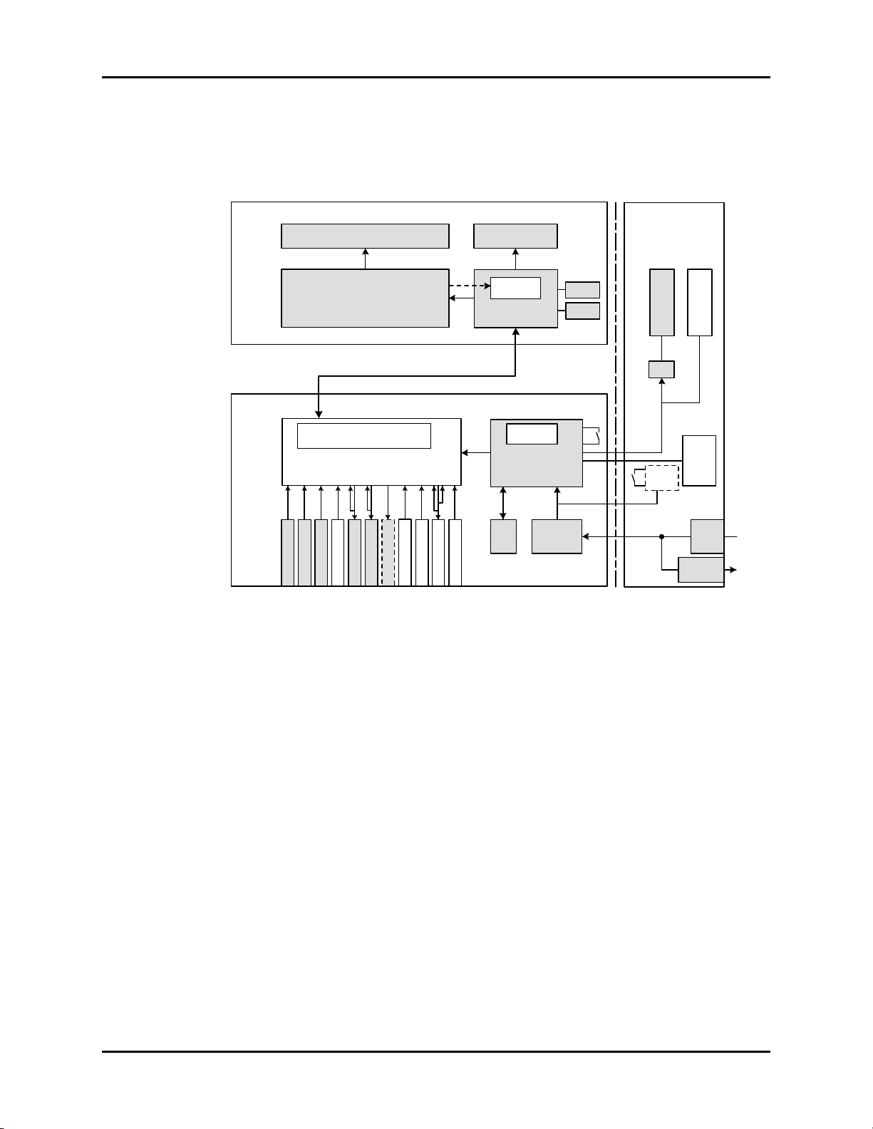
1.4 Electrical Supply
1.4.1 Electrical components
FIGURE 1-5 Electrical Components Overview
AS3000™ Service Manual 0070-10-0683 1 - 11
Ventilator Control and Drive Theory of Operation
1.5 Ventilator Control and Drive
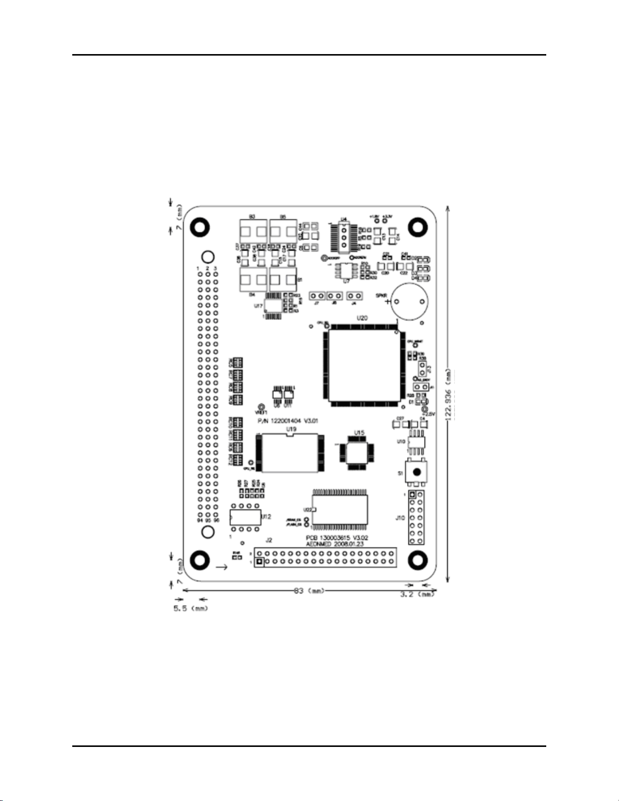
1.5.1 BDU (Basic Digital Unit)
The BDU serves as the active ventilator control. The BDU controls the actions of the PEEP,
calibration, and proportional valves, and reads the signal flow, and pressure sensors and
valves
FIGURE 1-6 BDU Control Board, Top View
1 - 12 0070-10-0683 AS3000™ Service Manual
Theory of Operation Ventilator Control and Drive
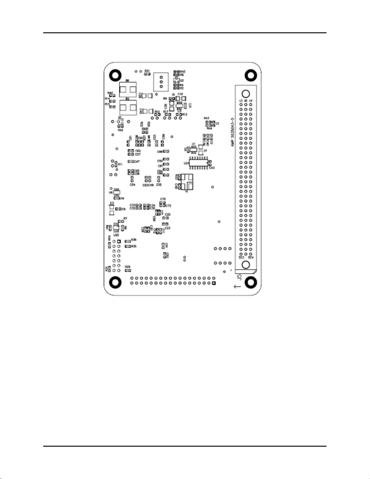
FIGURE 1-7 BDU Control Board, Bottom View
AS3000™ Service Manual 0070-10-0683 1 - 13
Ventilator Control and Drive Theory of Operation
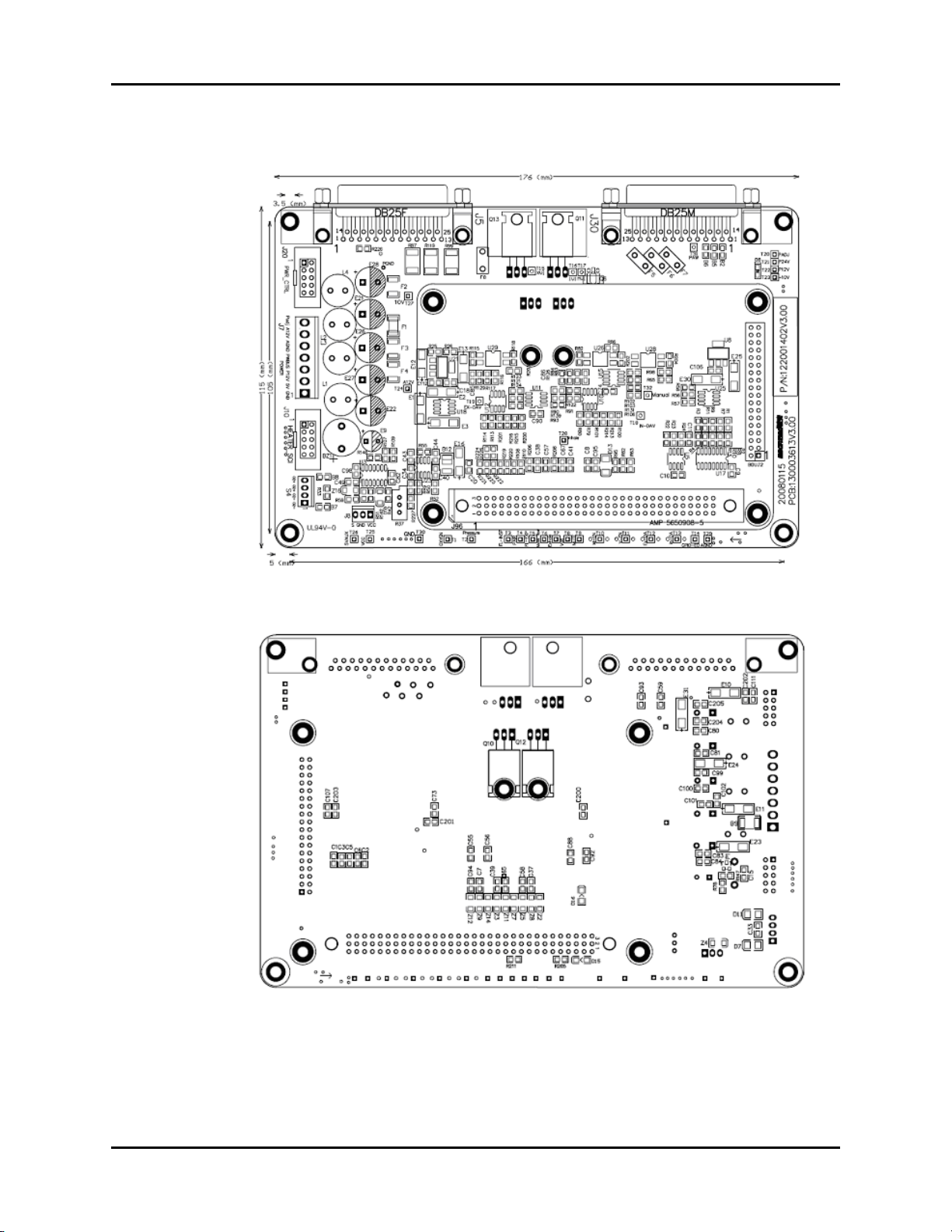
1.5.1.1 Amplifier Board
FIGURE 1-8 Amplifier Board, Top View
FIGURE 1-9 Amplifier Board, Bottom View
1 - 14 0070-10-0683 AS3000™ Service Manual

Theory of Operation Ventilator Control and Drive
O2 Sensor Input, S4
PIN NAME FUNCTION
1. O
2. O
3. O
4. O
-O
2
-O
2
+O
2
+O
2
Sensor Input -
2
Sensor Input -
2
Sensor Input +
2
Sensor Input +
2
DC Power Input, J7
PIN NAME FUNCTION
1. GND Power Ground
2. +5V Controller Logic Power
3. P12V Power 12V
4. PWBUS Power Bus 24V
5. GND Analog Ground
6. A12V Analog 12V
7. 5V/4.8V Power 5V/4.8V
Power Control, J20
PIN NAME FUNCTION
1. GND Ground
2. /PWON Power On Enable, Low active
3. PWEN Power On Enable, High active
4. 5VAUX 5V Auxiliary
5. DC_M AC/DC Monitor signal
6. PWBUS Power bus
7. BAT_M Battery Monitor signal
8. APE Auxiliary Power Enable
9. CHAR_SIGNAL Charge Status, No connection
10. /MUTE Mute, No connection
Signals and Power to Keyboard, J5
PIN NAME FUNCTION
1. ENPW Power Enable, High active
2. /PWON / Power on Enable, Low active
3. 5VAUX 5V Auxiliary
4. APE Auxiliary Power Enable
5. GND Ground
6. TTLRX TTL Receive
7. 232ARX RS232A Receive
8. 232BRX RS232B Receive
9. GND Ground
AS3000™ Service Manual 0070-10-0683 1 - 15

Ventilator Control and Drive Theory of Operation
Signals and Power to Keyboard, J5 (Continued)
PIN NAME FUNCTION
10. PWBUS PowerBus
11. PWBUS PowerBus
12. PWBUS PowerBus
13. GND Ground
14. GND Ground
15. DC24V DC24V monitor
16. BATV+ Battery monitor
17. /MUTE No connection
18. GND Ground
19. TTLTX TTL Transmit
20. 232ATX RS232A Transmit
21. 232BTX RS232B Transmit
22. GND Ground
23. PWBUS PowerBus
24. PWBUS PowerBus
25. GND Ground
Signals and Power to Sensor Board, J30
PIN NAME FUNCTION
1. A+12V Analogue +12V
2. FL_INS Import flow
3. FL_EXP Export flow
4. FM_FL Flowmeter flow
5. Pair Pressure of air
6. Paw Pressure inside air way
7. Pgas Pressure gas supply status
8. GND Ground
9. AGND Analog Ground
10. AGND Analog Ground
11. P24V Power 24V
12. P24V Power 24V
13. P24V Power 24V
14. P12V Power 12V
15. P12V Power 12
16. P5V Power 5V
17. P5V Power 5V
18. Inhale Inspire Valve
19. Man Manual/AUTO Valve
20. Exhale Expire Valve
21. Exhale Expire Valve
22. AGND Analog Ground
1 - 16 0070-10-0683 AS3000™ Service Manual

Theory of Operation Ventilator Control and Drive
Signals and Power to Sensor Board, J30 (Continued)
PIN NAME FUNCTION
23. AGND Analog Ground
24. AGND Analog Ground
25. AGND Analog Ground
Bus to BDU, J96
PIN NAME FUNCTION
1 - 3 5V 5V Power
4 - 6 GND Ground
Test Point Definition
DESIGNATOR NAME FUNCTION RANGE
T1 FIO
T2 Pgas Pressure switch of gas supply,
T3 FL_INSP Inspire Flow signal 0.20-0.30V (0 flow)
T4 Pair Absolute Pressure of air way 1.7-2.1V (atmospheric
T5 FL_EXP Expire flow signal 0.20-0.30V (0 flow)
T6 Fm_fl Flow of flowmeter 0.25-0.51V (flowmeter off)
T7 AD-Exhale PEEP valve, current feedback Level depends on PEEP
T8 Volt Internal power inspect
T9 MUTE Not used
T10 M-EN Manual/Auto mode select
T11 V-EN Valves enable Input Global valve enable signal.
T12 EX-DA Exhale DA output
T13 In-DA Inhale DA output
T14 GS_ST gas supply status, high active
T15 XVI unamplified version of T7
T16 IVI unamplified version of T28
T17 MVI Manual-Valve current feedback
T18 IVG Proportional valve drive signal,
T19 XVG PEEP valve drive signal - drives
T20 PADJ Power 4.8V 4.8V
T21 P24V Power 24V 24V
T22 P12V Power 12V 12V
ADC input of O2 Sensor 0.25-0.51V (In AIR)
2
low active
pressure)
setting and vent mode. No
activity may indicate open
connection from driver to
valve (ie. bad cable)
Must be active for valves to
operate.
Level depends on machine
drives T16 and T28
T15 and T7
settings.
Level depends on PEEP
setting and vend mode.
AS3000™ Service Manual 0070-10-0683 1 - 17
 Loading...