


PM-8000
Portable Multi-parameter
Patient Monitor
Operation Manual


Intellectual Property Statement
SHENZHEN MINDRAY BIO-MEDICAL ELECTRONICS CO., LTD. (hereinafter called
Mindray) owns the intellectual property rights to this product and this manual. This
manual may refer to information protected by copyrights or patents and does not convey
any license under the patent rights of Mindray, nor the rights of others. Mindray does not
assume any liability arising out of any infringements of patents or other rights of third
parties.
Mindray intends to maintain the contents of this manual as confidential information.
Disclosure of the information in this manual in any manner whatsoever without the
written permission of Mindray is strictly forbidden. Release, amendment, reproduction,
distribution, rent, adaption and translation of this manual in any manner whatsoever
without the written permission of Mindray is strictly forbidden
and are the registered trademarks or trademarks owned by Mindray
in China and other countries. All other trademarks that appear in this manual are used
only for editorial purposes without the intention of improperly using them. They are the
property of their respective owners.
Contents of this manual are subject to changes without prior notice.
For this Operation Manual, the issued Date is August 2005 (Version: 2.5).
© 2002-2005 Shenzhen Mindray Bio-Medical Electronics Co., Ltd. All rights reserved.
I

Manufacturer’s Responsibility
All information contained in this manual is believed to be correct. Mindray shall not be
liable for errors contained herein nor for incidental or consequential damages in
connection with the furnishing, performance, or use of this manual.
Mindray is responsible for safety, reliability and performance of this product only in the
condition that:
all installation operations, expansions, changes, modifications and repairs of
this product are conducted by Mindray authorized personnel; and,
the electrical installation of the relevant room complies with the applicable
national and local requirements; and,
this product is operated under strict observance of this manual.
Warranty
This warranty is exclusive and is in lieu of all other warrantyies, expressed or implied,
including warranties of merchantability or fitness for any particular purpose.
Exemptions
Mindray's obligation or liability under this warranty does not include any transportation or
other charges or liability for direct, indirect or consequential damages or delay resulting
from the improper use or application of the product or the use of parts or accessories not
approved by Mindray or repairs by people other than Mindray authorized personnel.
This warranty shall not extend to
any Mindray product which has been subjected to misuse, negligence or
accident; or
any Mindray product from which Mindray's original serial number tag or
product identification markings have been altered or removed; or
any product of any other manufacturer.
II

Return Policy
In the event that it becomes necessary to return a unit to Mindray, follow the instructions
below.
1. Obtain a return authorization.
Contact the Mindray Service Department and obtain a Mindray Customer Service
Authorization Number. The Mindray Customer Service Authorization Number must
appear on the outside of the shipping container. Return shipments will not be accepted if
the Mindray Customer Service Authorization Number is not clearly visible. Please
provide the model number, serial number, and a brief description of the reason for return.
2. Freight policy
The customer is responsible for freight charges when this product is shipped to Mindray
for service (including any relevant customs fees or other freight related charges).
3. Return address
Please send the part(s) or equipment to the address offered by Customer Service
Department.
III

Contact Information
Manufacturer:
Address:
Tel:
Fax:
Website:
EC
Representative:
Address:
Tel:
Fax:
Shenzhen Mindray Bio-Medical Electronics Co., Ltd.
Mindray Building, Keji 12th Road South, Hi-tech Industrial Park,
Nanshan, Shenzhen 518057 P.R. China
+86 755 26522479 +86 755 26582888
+86 755 26582500 +86 755 26582501
www.mindray.com.cn
Shanghai International Holding Corp. GmbH (Europe)
Eiffestraße 80, 20537 Hamburg Germany
0049-40-2513175
0049-40-255726
IV
Equipment Symbols
This symbol means 'BE CAREFUL '. Refer to the manual.
This symbol indicates that the instrument is IEC 60601-1 T y pe CF
equipment. The unit displaying this symbol contains an F-Type isolated
(floating) patient applied part providing a high degree of protection
against shock, and is suitable for use during defibrillation.
Equipotential grounding system.
Protective earth ground.
Power On/Off
This mark means that this device is fully in conformance with the
Council Directive Concerning Medical Devices 93/42/EEC. The
number adjacent to the CE marking (0123) is the number of the
EU-notified body that certified meeting the requirements of Annex II of
the Directive.
The following definition of the WEEE label applies to EU member
states only.
This symbol indicates that this product should not be treated as
household waste. By ensuring that this product is disposed of correctly,
you will help prevent bringing potential negative consequences to the
environment and human health. For more detailed information with
regard to returning and recycling this product, please consult the
distributor from whom you purchased it.
* For system products, this label may be attached to the main unit only.
NOTE: Points to be noted.
CAUTION: Points to be noted to avoid damage to the equipment.
WARNING: Points to be noted to avoid injury to the patient and the
operator.
V

FOR YOUR NOTES
VI

Contents
Chapter 1 Introduction...................................................................................................1-1
1.1 General Information................................................................................................... 1-3
1.2 Screen Display ..........................................................................................................1-5
1.3 Button Functions ....................................................................................................... 1-8
1.4 Interfaces.................................................................................................................1-10
1.5 Batteries ..................................................................................................................1-13
Chapter 2 Getting Started..............................................................................................2-1
2.1 Open the Package and Check..................................................................................2-1
2.2 Connect the Power Cables........................................................................................ 2-1
2.3 Power on the Monitor................................................................................................2-2
2.4 Connect Patient Sensors........................................................................................... 2-2
2.5 Check the Recorder .................................................................................................. 2-3
Chapter 3 System Menu.............................................................................................. 3-1
3.1 Patient Information Setup.......................................................................................... 3-2
3.2 Default Setup............................................................................................................. 3-3
3.3 System Setup............................................................................................................3-5
3.4 Selection Setup ....................................................................................................... 3-1 1
3.5 Monitor Version....................................................................................................... 3-12
3.6 Drug Calculation...................................................................................................... 3-13
3.7 Maintenance............................................................................................................ 3-13
3.8 DEMO Function....................................................................................................... 3-18
Chapter 4 Face Select .................................................................................................4-1
4.1 Select Operating Screen........................................................................................... 4-1
4.2 Standard Screen........................................................................................................4-1
4.3 Trend Screen............................................................................................................. 4-2
4.4 oxyCRG Screen ........................................................................................................ 4-3
4.5 Viewbed Screen........................................................................................................ 4-4
Chapter 5 Alarm...........................................................................................................5-1
5.1 Alarm Modes.............................................................................................................. 5-1
5.2 Alarm verification during power on............................................................................ 5-4
5.3 Alarm Cause..............................................................................................................5-4
5.4 SILENCE and PAUSE...............................................................................................5-5
5.5 Parameter Alarm....................................................................................................... 5-6
5.6 When an Alarm Occurs............................................................................................. 5-7
Chapter 6 Freeze..........................................................................................................6-1
6.1 General...................................................................................................................... 6-1
6.2 Enter/Exit Freeze Status............................................................................................6-1
6.3 Frozen Menu .............................................................................................................6-2
6.4 Reviewing Frozen Waveform....................................................................................6-2
1

Contents
6.5 Recording Frozen Waveform ....................................................................................6-3
Chapter 7 Recording ...................................................................................................7-1
7.1 General Information on Recording............................................................................7-1
7.2 Recording Type.........................................................................................................7-1
7.3 Recording Startup......................................................................................................7-4
7.4 Recorder Operations and Status Messages............................................................. 7-5
Chapter 8 Trend and Event......................................................................................... 8-1
8.1 Trend Graph.............................................................................................................. 8-1
8.2 Trend Table................................................................................................................8-3
8.3 NIBP Recall...............................................................................................................8-4
8.4 Alarm Event Recall.................................................................................................... 8-5
Chapter 9 Drug Calculation and Titration Table.......................................................9-1
9.1 Drug Calculation........................................................................................................ 9-1
9.2 Titration Table............................................................................................................ 9-3
Chapter 10 Patient Safety ...........................................................................................10-1
Chapter 11 Care / Cleaning......................................................................................... 11-1
11.1 System Check........................................................................................................ 11-1
11.2 General Cleaning................................................................................................... 11-2
11.3 Cleaning Agents.....................................................................................................11-2
1 1.4 Sterilization ............................................................................................................ 11-3
1 1.5 Disinfection............................................................................................................ 11-3
Chapter 12 ECG/RESP Monitoring.............................................................................12-1
12.1 What Is ECG Monitoring........................................................................................12-1
12.2 Precautions during ECG Monitoring...................................................................... 12-1
12.3 Monitoring Procedure............................................................................................12-2
12.4 ECG Screen Hot Keys...........................................................................................12-6
12.5 ECG Menu............................................................................................................. 12-7
12.6 ECG Alarm Information and Prompt.................................................................... 12-11
12.7 ST Segment Monitoring (optional).......................................................................12-12
12.8 Arr. Monitoring (optional).....................................................................................12-16
12.9 Measuring RESP................................................................................................. 12-20
12.10 Maintenance and Cleaning................................................................................12-24
Chapter 13 SpO2 Monitoring......................................................................................13-1
13.1 PART 1 (MASIMO S pO2 board configuration)...................................................... 13-1
13.1.1 Precautions ........................................................................................................ 13-3
13.1.2 Monitoring Procedure.........................................................................................13-5
13.1.3 Sensors and Accessories:..................................................................................13-8
13.1.4 Alarm Description and Prompt.......................................................................... 13-10
13.1.5 Masimo Information..........................................................................................13-13
13.2 PART 2 (MINDRAY SpO2 board configuration)..................................................13-14
13.2.1 What is SpO2 Monitoring..................................................................................13-14
13.2.2 Precautions during SpO2/Pulse Monitoring.....................................................13-15
13.2.3 Monitoring Procedure.......................................................................................13-16
13.2.4 Limitations for Measurement............................................................................13-18
2

Contents
13.2.5 SpO2 Menu......................................................................................................13-18
13.2.6 Alarm Description and Prompt.......................................................................... 13-21
13.2.7 Maintenance and Cleaning...............................................................................13-22
Chapter 14 NIBP Monitoring....................................................................................... 14-1
14.1 Introduction............................................................................................................ 14-1
14.2 NIBP Monitoring.................................................................................................... 14-1
14.3 NIBP SETUP menu...............................................................................................14-6
14.4 NIBP Alarm Message ............................................................................................14-9
14.5 Maintenance and Cleaning.................................................................................. 14-11
Chapter 15 TEMP Monitoring......................................................................................15-1
15.1 TEMP Monitoring...................................................................................................15-1
15.2 TEMP SETUP Menu..............................................................................................15-2
15.3 TEMP Alarm message........................................................................................... 15-2
15.4 Care and Cleaning ................................................................................................15-3
Chapter 16 IBP Monitoring..........................................................................................16-1
16.1 Introduction............................................................................................................ 16-1
16.2 Precautions during IBP Monitoring........................................................................ 16-1
16.3 Monitoring Procedure............................................................................................16-2
16.4 IBP Menu............................................................................................................... 16-3
16.5 Alarm Information and Prompts............................................................................. 16-9
16.6 Maintenance and Cleaning.................................................................................. 16-11
16.7 ICP Transducer ICT/B (Optional Accessory) .................................................16-12
Chapter 17 Accessories.............................................................................................. 17-1
17.1 ECG Acce ss ories.................................................................................................. 17-1
17.2 SpO2 Accessories.................................................................................................17-2
17.3 NIBP Accessories..................................................................................................17-3
17.4 TEMP Accessories................................................................................................ 17-3
17.5 IBP Accessories..................................................................................................... 17-4
Appendix A EC Declaration of Conformance.............................................................. A-1
Appendix B Product Specification............................................................................... B-1
Appendix C EMC............................................................................................................ C-1
Appendix D System Alarm Prompt............................................................................... D-1
3

FOR YOUR NOTES
Contents
4

Chapter 1 Introduction
For an overall introduction to the monitor, please refer to General Information.
For various messages displayed on the screen, please refer to Screen Display.
For basic operating instructions, please refer to Button Function.
For allocation of interface sockets, please refer to Interfaces.
For important facts to be noted during the battery recharging procedure, please refer to
Built-in Battery.
For safety precautions of the monitor, please refer to Patient Safety.
Warning
PM-8000 Portable Multi-Parameter Patient Monitor is intended for clinical monitoring
application with operation only granted to appropriate medical staff.
Warning
Monitor can only monitoring one patient at a time.
Warning
There could be hazard of electrical shock by opening the monitor casing. All servicing
and future upgrading to this equipment must be carried out by personnel trained and
authorized by Mindray.
Warning
Possible explosion hazard if used in the presence of flammable anesthetics or other
flammable substance in combination with air, oxygen-enriched environments, or
nitrous oxide.
.
Warning
You must verify if the device and accessories can function safely and normally before
use.
Warning
You must customize the alarm setups according to individual patient situation and
make sure that alarm sound can be activated when alarm occurs.
Warning
Do not use cellular phone in the vicinity of this device. High level electromagnetic
radiation emitted from such devices may greatly affect the monitor performance.
1-1

Introduction
Warning
Do not touch the patient, table, or the devi ce during defibrillation.
Warning
Devices connected to the monitor shall form an equipotential system (protectively
earthed).
Warning
When used with Electro-surgery equipment, you (doctor or nurse) must give top
priority to the patient safety.
Warning
Do not place the monitor or external power supply in any position that might cause it
to fall on the patient. Do not lift the monitor by the power supply cord or patient cable,
use only the handle on the monitor.
Warning
Consult IEC-601-1-1 for system interconnection guidance. The specific requirements
for system interconnection are dependent upon the device connected to the monitor
and the relative locations of each device from the patient, and the relative location of
the connected device to the medically used room containing the monitor. In all
circumstance the monitor must be connected to a grounded AC power supply. The
monitor is referred to as an IEC 601/F device in the summary of situations table
contained in IEC 601-1-1.
Warning
Dispose of the packaging material, observing the applicable waste control regulations
and keeping it out of children’s reach.
Warning
This equipment is accord with the standard CISPR11 (EN55011) class A.
Warning
Grounding:
Connect the monitor only to a three-wire, grounded, hospital-grade receptacle. The
three-conductor plug must be inserted into a properly wired three-wire receptacle; if a
three-wire receptacle is not available, a qualified electrician must install one in
accordance with the governing electrical code.
Do not under any circumstances remove the grounding conductor from the power
plug.
Do not use extension cords or adapters of any type. The power cord and plug must be
intact and undamaged.
1-2

Introduction
If there is any doubt about the integrity of the protective earth conductor arrangement,
operate the monitor on internal battery power until the AC power supply protective
conductor is fully functional.
Note
The software was developed per IEC601-1-4. The possibility of hazards arising from
errors in the software program is minimized.
Caution
At the end of its service life, the product described in this manual, as well as its
accessories, must be disposed of in compliance with the guidelines regulation the
disposal of such products. If you have questions concerning disposal of the product,
please contact MINDRAY or it s representatives.
If you have any doubt to the grounding layout and its performance, you must use the
built-in battery to power the monitor.
1.1 General Information
Environment:
Temperature
Working 0 ~ 40 °C
Transport and Storage -20 ~ 60 °C
Humidity
Working 15% ~ 95 %
Transport and Storage 10% ~ 95 %
Altitude
Working -500 ~ 4,600m (-1,600 to 15,000ft)
Transport and Storage -500 ~ 13,100m (-1,600 to 43,000ft)
Power Supply
100/240 (V) AC, 50/60 (Hz)
Pmax = 100 VA
FUSE T 1.6A
Contraindications: None
General instruction:
PM-8000 is a Portable Patient Monitor that has abundant monitoring functions and is used for
the clinical monitoring of adult, pediatric and neonate. In addition, the user may select the
different parameter configuration according to different requirements.
PM-8000 can be connected to the central monitoring system via the Mindray network so as to
form a network monitoring system.
PM-8000 (Figure 1-1) can monitor vital signals as ECG, Respiratory Rate, SpO2, NIBP, TEMP,
1-3
Introduction
IBP. It integrates parameter measuring modules, display and recorder in one device, featuring
in compactness, lightweight and portability. Replaceable built-in battery facilitates
transportation of patient. Large high-resolution display provides clear view of 5 waveforms
and full monitoring parameters.
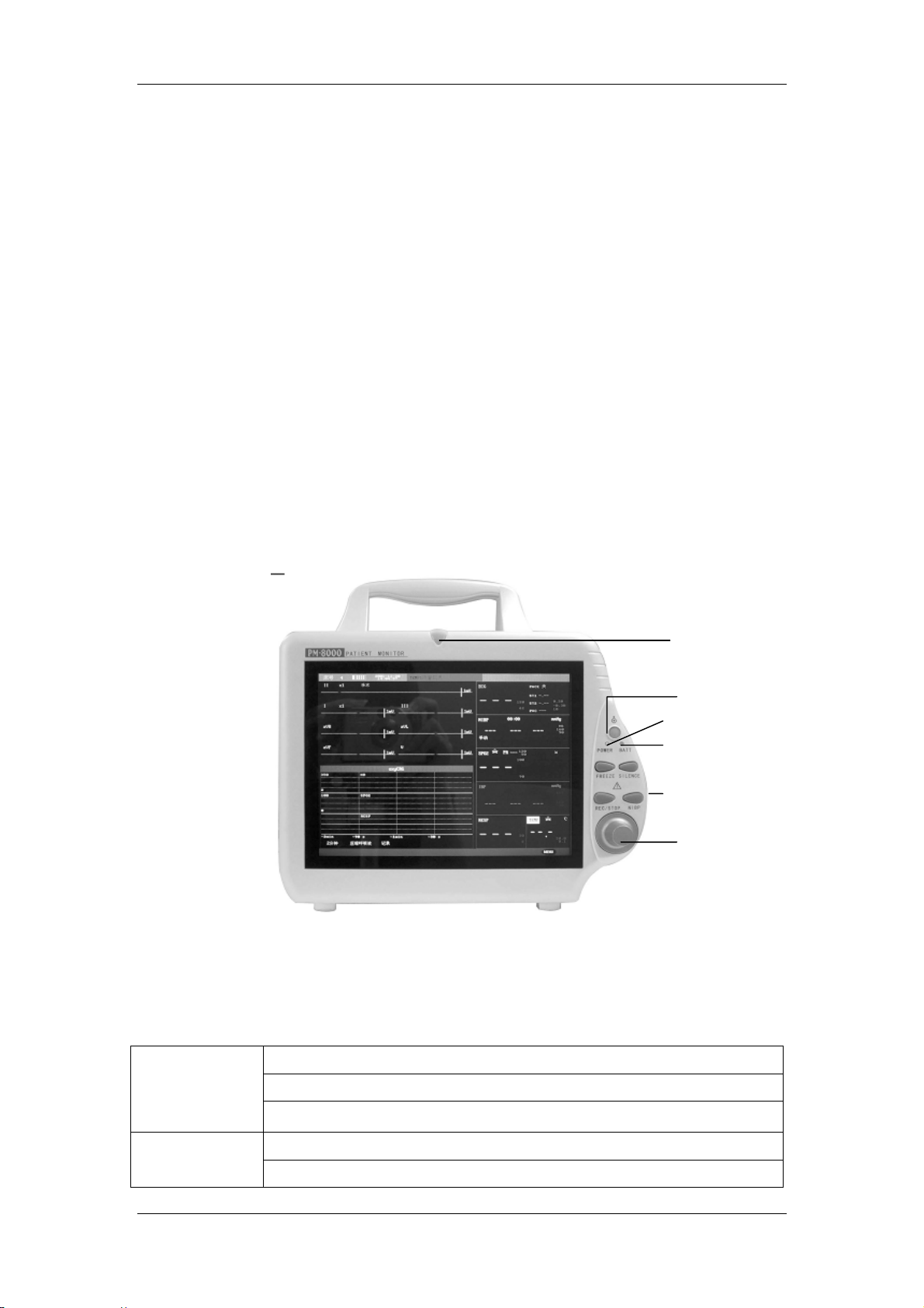
The power switch (POWER) of the monitor is on the upper left part of the front panel (② in the
figure below). The POWER LED (③ in the figure below) is used to indicate the AC Mains
condition. This LED is illuminated when AC Mains is connected. BATT LED (④ in the figure
below) is on the left side of POWER LED, used to indicate the battery condition. This LED is
off when no battery is loaded. After the battery is loaded, this BATT. LED will be illuminated if
AC Mains is connected, or lighted off when AC Mains is disconnected and at the same time
the monitor is not powered on, or flashes when though AC Mains is disconnected but the
monitor is powered on. The alarm indicator (ALARM) is on the upper part of the front panel
(① in the figure below), which will flash as soon as any alarm event happens. Sensor and
probe sockets are on the left side of the monitor while the recorder is on the right side. Other
sockets and power connector is on the rear panel of the monitor.
PM-8000 is a user-friendly device with operations conducted by a few buttons on the front
panel (⑤in Figure 1-1) and a rotary knob (⑥in Figure 1-1). Refer to 1.3 Button Functions for
details.
①
①
②
③
④
⑤
⑥
Figure 1-1 PM-8000 Portable Patient Monitor
The visible LEDs are CLASS 1 LED PRODUCT according with EN 60825-1 A11 Oct 1996.
PM-8000 Portable Patient Monitor performs monitoring of:
Heart Rate (HR)
ECG
RESP
2-channel ECG waveforms
Arrhythmia and S-T segment analysis(optional)
Respiratory Rate (RR)
Respiration Waveform
1-4
Introduction
SpO2
NIBP
TEMP
IBP
PM-8000 provides extensive functions as visual & audible alarm, storage and report printout
for trend data, NIBP measurements, and alarm events, oxyCRG, viewbed, and drug dose
calculation function is provided either.
Oxygen Saturation (SpO2), Pulse Rate (PR)
SpO2 Plethysmogram
Systolic Pressure (NS), Diastolic Pressure (ND), Mean Pressure (NM)
Channel-1 Temperature (T1), Channel-2 Temperature (T2), Temperature
Difference between two channels (TD)
IBP SYS, DIA, MAP
IBP waveform
1.2 Screen Display
The display of PM-8000 parameter monitor is a color LCD, which can display the collected
patient parameters, waveforms, alarm information as well as bed number, time and monitor
status, etc.
The screen is divided into three areas(Figure 1-2): Information area①④; waveform area②;
parameter area③.
①
②
④
Figure 1-2 PM-8000 Main Display
Information Area
The Message Area is at the top part of the screen, displaying the current status of both the
monitor and the patient.
Patient information include:
③
1-5

Introduction
BED NO Bed numbers of all patients under monitoring
Patient type Three options: Adult, Pediatric, Neonate
“01-01-2000” Current date
“13:51:32” Current date and time
Male Patient sex, Male or Female
ZHANG SHAN Patient name This item will display blank if the operator does not
input patient name
Other information in the Message Area will appear and disappear together with the reported
status. According to the content, the information is divided into:
■ Prompt information, reporting the current status of the monitor or sensor/probe, which
always appears to the right of the system time. When this information appears, it will cover
patient sex and name.
■
flag for alarm PAUSE. Press “SILENCE” button once (less than 1 second) to mute all
alarm sounds are muted for the time being and the flag appears at the same time. Press the
button again to terminate the PAUSE status. The duration for PAUSE status can be 1 minute,
2 minutes or 3 minutes.
■
flag for alarm SILENCE. Press “SILENCE” button once (more than 1 second) to
manually mute the alarm sound and this flag appears at the same time. The SILENCE status
terminates when you discharge the status or new alarm occurs.
■
flag for Alarm Volume Off. It appears indicating that you have closed the alarm
sound permanently. This status terminates when you discharges the status.
Note
If symbol appears, the system will no longer give audible alarm sound. You
must be very careful in using this function. Two ways can be used to discharge this
status. One is set the alarm volume to an option other than OFF in the USER MAITAIN
menu. The other method is to press SILENCE button to make the flag turn to
. And
then press SILENCE again and the system will restore the normal alarm status.
■ Parameter alarm information is displayed always in the upper right corner of the screen.
■ When the waveforms on the screen are frozen, the FREEZE prompt will appear in the
bottom part of the screen.
Waveform / Menu Area
The waveform area can maximally display 5 waveforms. The displaying order of the
waveforms on the screen can be adjusted. For the maximum configuration, the waveforms
provided by the system for selection are: 2 ECG waveforms, SpO2 waveform, IBP waveforms,
1-6

Introduction
RESP waveform.
All the waveforms in the system are listed out in the “WAVEFORM SETUP” menu. The user
may select the waveform to be displayed and adjust their displaying positions. The specific
method is illustrated in the part: Tracing Waveforms Selection.
The name of the waveform is displayed on the upper left part of the waveform. The user may
choose ECG lead based on the requirements. The gain of the channel and the filter way are
also displayed on each ECG waveform. A 1mV scale bar is also displayed to the right side of
ECG waveform. The IBP waveform scale can also be selected according to the actual
requirement. Its range is described in the part: Measure IBP. In the IBP waveform area, the
waveform scale is displayed. The three dotted lines for each IBP waveform form up to down
represent respectively the upper limit scale, reference scale and lower limit scale. The values
of these three scales can be set. The specific method is given in the part: Measure IBP.
When menu is wanted during screen operation, the menu always occupies the fixed position
in the middle part of the waveform area, therefore part of waveform can not be viewed
temporarily. After exiting the menu, the system will restores the original screen.
The user may set up the rate to refresh the waveform. The method to adjust the refreshing
rate of each waveform is discussed in the setup description of each parameter.
Parameter Area
The parameter area lies to the right side of the waveform area, whose position basically
corresponds to the waveform. The parameters displayed in the parameter area include:
ECG
— heart rate or pulse rate (unit: beats/minute)
— The ST analyzing result of channel 1 and 2: ST1, ST2 (unit: mV)
— PVCs(unit: times/minute)
NIBP
— From left to right, there are Systolic pressure, Mean pressure and Diastolic
pressure(unit: mmHg or kPa)
SpO
2
— SpO
(unit: %)
2
— Pulse Rate(unit: beats/minute)(When “BOTH” item is selected)
IBP
— Blood Pressure: Systolic, Mean, and Diastolic values are displayed from left
to right.(unit: mmHg or kPa).
RESP
— Respiration Rate(unit: times/minute)
TEMP
— Temperature of channel 1 and 2: T1, T2 and the difference between them
TD. (unit: ℃ or ℉)
Alarm lamp and alarm status:
In normal status: the alarm lamp is not on.
When alarm exists, the alarm lamp flashes or lights on. The color of the lamp corresponds to
1-7

Introduction
the alarm level. Refer to related chapter: Alarm.
For the details of alarm information and prompt information, refer to the related content of
each parameter in related chapter.
Warning
Always verify the audible and visual (LED) alarms when PM-8000 powers on.
1.3 Button Functions
All the operations to PM-8000 are through the buttons and a knob at the bottom of the screen.
The names of the buttons are above them. They are (from left to right, Figure 1-3):
①
②
④
Figure 1-3 PM-8000 Buttons and Knob
③
⑤
⑥
POWER(Figure 1-3 ①)
Press to turn on/off the monitor.
FREEZE(Figure 1-3 ②)
Press this button and the system will access the FREEZE status. In this status the user may
review the waveform of 40 seconds. Also, the frozen waveform can be printed out. In the
FREEZE status, press this button again to discharge the FREEZE status. For detailed
information, refer to related chapter: Freeze.
SILENCE(Figure 1-3 ③)
Push this button to suspend alarm for maximum 3 minutes (with 1 minute, 2 minutes and 3
minutes selectable). In Alarm PAUSE status, a
Push this button for more than 1 second to mute all kinds of sounds (including alarm sound,
heart beat, pulse tone, key sound). At the same time, a
Message Area. Push this button again to restore all kinds of sounds and the
1-8
symbol appears in the Message Area.
symbol appears in the
symbol

Introduction
appears from the screen.
Note
If new alarm occurs in Alarm Pause/Silence status, the system will discharge
Pause/Silence status automatically. For specific rules, see Chapter Alarm.
Note
The system will begin to give alarm information again once there exist alarm-triggering
event. Nevertheless, remember pushing SILENCE button can permanently shut off
audible alarm sound of ECG LEAD OFF and SPO2 SENSOR OFF alarms.
REC/STOP(Figure 1-3 ④)
Press to start a real time recording. The recording time is set in REC TIME of RECORD
SETUP submenu. Press during recording to stop the recording. For detailed information, refer
to related chapter.
NIBP(Figure 1-3 ⑤)
Press to inflate the cuff to start a blood pressure measurement. When measuring, press to
cancel the measurement and deflate the cuff.
Rotary knob(Figure 1-3 ⑥)
The user may use the rotary knob to select the menu item and modify the setup. It can be
rotated clockwise or counter-clockwise and pressed like other buttons. The user may use the
knob to realize the operations on the screen and in the system menu and parameter menu.
Method to use the knob to operate on the screen:
The rectangular mark on the screen that moves with the rotation of the knob is called “cursor”.
Operation can be performed at any position at which the cursor can stay.
When the cursor is in the waveform area, the user may immediately modify the current setup.
When the cursor is in the parameter area, the user may open the setup menu of the
corresponding parameter module so as to set up the menu items of the module.
Operating method:
■ Move the cursor to the item where the operation is wanted
■ Press the knob
■ One of the following four situations may appear:
1. The cursor with background color may become into the frame without
background color, which implies that the content in the frame can change with
the rotation of the knob.
2. Menu or measuring window may appear on the screen, or the original menu is
replaced by the new menu.
3. A check mark “√” appears at the position, indicating that the item is confirmed.
4. The system immediately executes a certain function.
1-9
Introduction
t
1.4 Interfaces
For the convenience of operation, the different kinds of interfaces are in different parts of the
monitor.
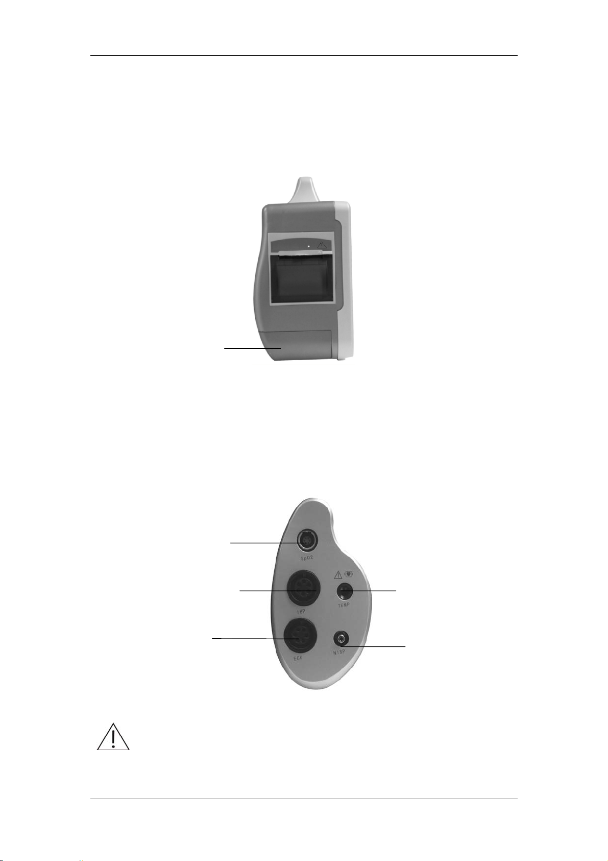
At the right side is the recorder’s paper inlet cover as shown in Figure 1-4.
Battery Slo
Figure 1-4 Right Side
At the left side are the connectors to patient cables and the sensors, as shown in Figure 1-5.
① Socket for Spo2 Sensor
② Socket for IBP transducer
③ Socket for TEMP probe
④ Socket for ECG cable
⑤ Socket for NIBP cuff
①
② ③
④
Figure 1-5 Left Side
⑤
This symbol means “BE CAREFUL". Refer to the manual.
1-10
Introduction
Indicates that the instrument is IEC 60601-1 Type CF equipment. The unit displaying this
symbol contains an F-Type isolated (floating) patient applied part providing a high degree of
protection against shock, and is suitable for use during defibrillation.
①
②
③
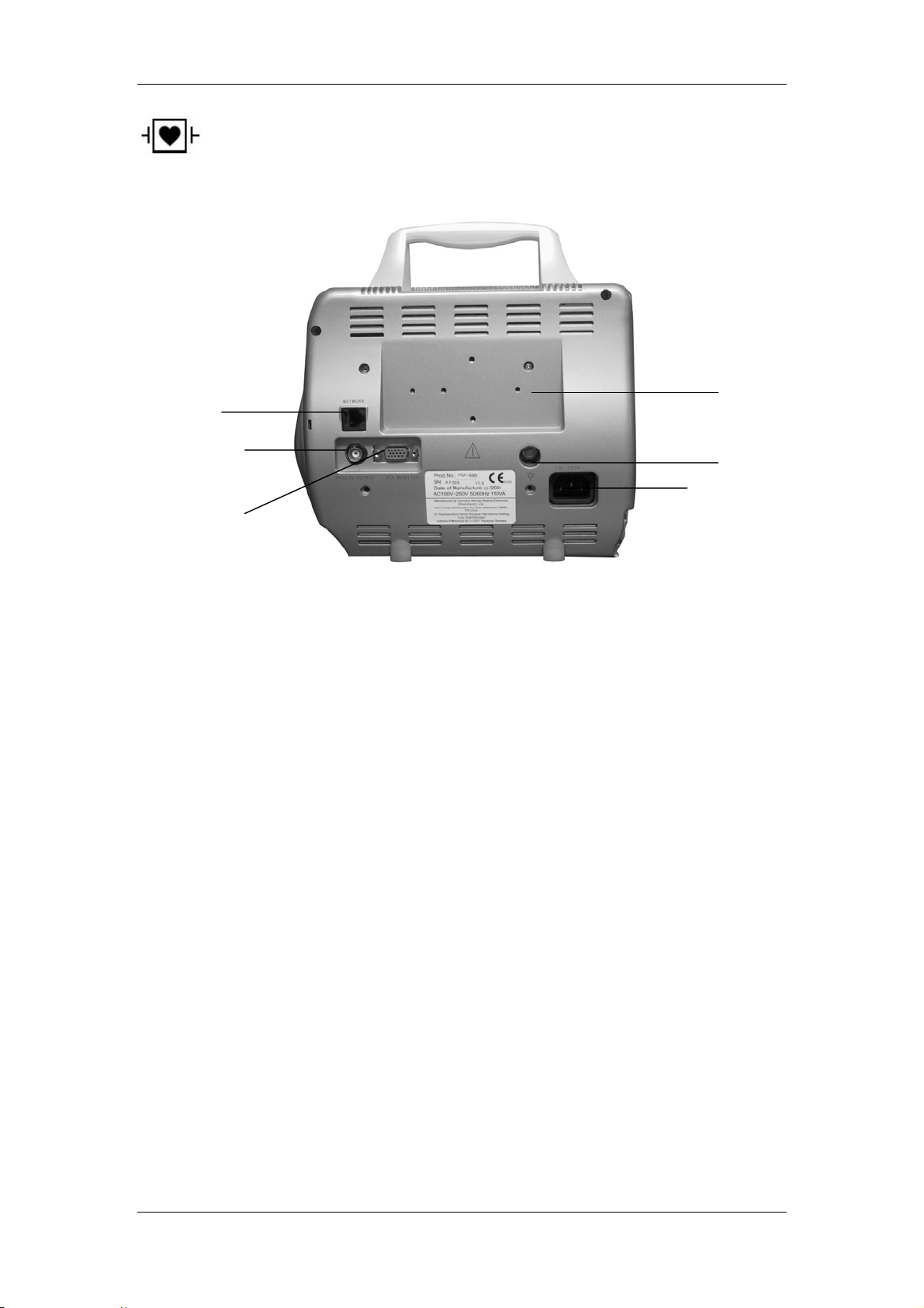
On the rear panel are the following sockets, shown in Figure 1-6
■ Power Supply: 100 ~ 240 (VAC), 50/60 (Hz). (Socket ⑤)
■ VGA MONITOR: (Socket ③)
Monitor interface for external standard VGA color monitor.
Working mode:800 × 600, 16 color, APA mode.
Signal: analog R G B 0.7 Vpp / 750 ohm
Hor. / Vert. TTL pos. / Neg.
Interface D-sub 15 pin
Pin 1. Red Video
Figure 1-6 Rear Panel
Pin 2. Green Video
Pin 3. Blue Video
Pin 4. Ground
Pin 5. NC
Pin 6. Red Ground
Pin 7. Green Ground
Pin 8. Blue Ground
Pin 9. NC
Pin 10. Ground
Pin 11. NC
Pin 12. NC
Pin 13 Horizontal Sync.
Pin 14. Vertical Sync.
⑥
④
⑤
1-1 1

Introduction
Pin 15. NC
Appliance:
1) Install the VGA monitor in the same room with the patient but keep away from the
patient for more than 1.5m. The monitor is intended to be used as an assistant
monitoring device.
2) Plug and insert the connection cable while the VGA monitor is in power off status.
3) Power on at the same time, or power on the PM-8000 patient monitor after VGA.
4) Adjust brightness and contrast properly.
■
(Socket ④)
Equipotential grounding terminal for connection with the hospital’s grounding system.
■ AUX OUTPUT (socket ②)
This port is used for both Analog Output and NURSE CALL.
The user could select the function of this port in “NURSE CALL SETUP” menu of “USER
MAINTAIN” menu. Refer to the section about “USER MAINTAIN” menu to know the
detailed information.
ANALOG OUTPUT: connected to oscillograph and pen recorder. BNC Jack.
NURSE CALL: connected to the CALL system of the hospital by using dedicated
NURSE CALL cable.
Note
The output terminal of NURSE CALL cable has two leads in free status (ie., no distinction
between positive or negative). Before use, the service engineer from MINDRAY or equipment
engineer of the hospital must first install the accompanying connectors according to the real
situation of the CALL system of the hospital.
■ Network Interfaces (Socket ①): Standard RJ45 Socket.
■ Fixing hole of supporter(Socket ⑥).
Note
Monitor must be connected with specific network equipment such as Harb during
using net function.
Warning
Accessory equipment connected to the analog and digital interfaces must be certified
according to the respective IEC standards (e.g. IEC 60950 for data processing
equipment and IEC 60601-1 for medical equipment). Furthermore all configurations
shall comply with the valid version of the system standard IEC 60601-1-1. Everybody
who connects additional equipment to the signal input part or signal output part
configures a medical system, and is therefore responsible that the system complies
with the requirements of the valid version of the system standard IEC 60601-1-1. If in
doubt, consult the technical service department or your local representative.
1-12

Introduction
1.5 Batteries
This monitor is designed to operate run battery power when during transport or whenever the
power supply is interrupted. The battery is charged automatically when the monitor is
connected to AC power, no matter the monitor is powered on or not.
The battery symbol displayed on the main screen tells the status of the battery.
Besides, the battery indicator also indicates the status of the battery.
ON: The battery is being charged or the battery is fully charged.
OFF: No battery is inst alled. If the battery is installed but the monitor is not
The battery is installed in the battery slot. The solid part indicates its capacity.
No battery is installed in the battery slot.
connected to AC power and not turned on, the indicator will also be off.
Flashes: The monitor is powered by the internal battery.
The capacity of the internal battery is limited. When the battery capacity is too low, a high
level alarm is triggered and the “Battery two low” message is given in the technical alarms
area. At this moment, the AC power shall be applied to the monitor.
Note
Remove the battery before transport, or if the monitor is not likely to be used for an
extended period of time.
Warning
Keep the battery out of the reach of children.
Use only the battery specified by the manufacturer.
1.5.1 Battery Maintenance
Conditioning a Battery
A battery should be conditioned before it is used for the first time. A battery conditioning cycle
is one uninterrupted charge of the battery, followed by an uninterrupted discharge of the
1-13

Introduction
battery. Batteries should be conditioned regularly to maintain their useful life. Condition a
battery once when it is used or stored for two months, or when its run time becomes
noticeably shorter.
To condition a battery, follow this procedure:
1. Disconnect the monitor from the patient and stop all monitoring or measuring.
2. Insert the battery in need of conditioning in the battery slot of the monitor, and leave the
other slot empty if your minitor has two slots.
3. Apply AC power to the monitor and allow the battery to charge uninterrupted for 10 hours.
4. Remove AC power and allow the monitor to run from the battery until it shuts off.
5. Apply AC power again to the monitor and allow the battery to charge uninterrupted for 10
hours.
6. This battery is now conditioned and the monitor can be returned to service.
Checking a Battery
The performance of a rechargeable battery may deteriorate over time. To check the
performance of a battery, follow this procedure:
1. Disconnect the monitor from the patient and stop all monitoring or measuring.
2. Apply AC power to the monitor and allow the battery to charge uninterrupted for 10 hours.
3. Remove AC power and allow the monitor to run from the battery until it shuts off.
4. The operating time of battery reflects its performance directly.
If your monitor has two battery slots, you can check two batteries at the same time. Please
replace the battery or contact with the maintenance personnel if its operating time is
significantly lower than the specified time.
Note
Life expectancy of a battery depends on how frequent and how long it is used. For a
properly maintained and stored lead-acid or lithium ion battery, its life expectancy is
about 2 or 3 years respectively. For more aggressive use models, life expectancy can
be less. We recommend replacing lead acid batteries every 2 years and lithium ion
batteries every 3 years.
The battery might be damaged or malfunctioned if its operating time is too short after
being fully charged. The operating time depends on the configuration and operation.
For example, measuring NIBP more frequently will also shorten the operating time.
1-14

Introduction
1.5.2 Battery Recycling
When a battery has visual signs of damage, or no longer holds a charge, it should be
replaced. Remove the old battery from the monitor and recycle it properly. To dispose of the
batteries, follow local laws for proper disposal.
Warning
Do not disassemble batteries, or dispose of them in fire, or cause them to short circuit.
They may ignite, explode, leak or heat up, causing personal injury.
1-15

FOR YOUR NOTES
Introduction
1-16

Chapter 2 Getting Started
■ Open the package and check
■ Connect the power cables
■ Power on the monitor
■ Connect patient sensors
■ Check the recorder
Note
To ensure that the monitor works properly, please read Chapter Patient Safety, and
follow the steps before using the monitor.
2.1 Open the Package and Check
Open the package and take out the monitor and accessories carefully. Keep the package for
possible future transportation or storage. Check the components according to the packing list.
■ Check for any mechanical damage.
■ Check all the cables, modules and accessories.
If there is any problem, contact the distributor immediately.
2.2 Connect the Power Cables
Connection procedure of the AC power line:
Make sure the AC power supply complies with following specification: 100 ~ 240 VAC,
50/60 Hz.
Apply the power line provided with the monitor. Plug the power line to INPUT interface of
the monitor(Socket ⑤ in Figure 1-6). Connect the other end of the power line to a
grounded 3-phase power output.
Note
Connect the power line to the jack special for hospital usage.
Mindray does not provide MULTIPLE PORTABLE SOCKET-OUTLETS. IF use it, please
do not place it on the floor. Mindray advises that every one monitor uses one
MULTIPLE PORTABLE SOCKET-OUTLETS.
Connect to the ground line if necessary. Refer to Chapter Patient Safety for details.
2-1

Getting Started
Note
Make sure that the POWER lamp now lights. If it does not light, check your local power
supply. If the problem still exists, contact the local Customer Service Center.
The battery needs to be charged after transportation or storage. If the power supply is
not properly connected before turning on the monitor, it may not work properly
because of insufficient power. Connect the power supply to charge the battery.
2.3 Power on the Monitor
Press POWER(① in Figure 1-1) to power on the monitor. Then a beep will be heard and at
the same time the indicator will flash twice in yellow and red. After 10 seconds or so, the
system will enter monitoring screen after self-test, and you can perform normal monitoring
now.
During self-test, the software version will display.
Note
If the monitor finds any fatal error during self-test, it will alarm.
Check all the functions that may be used to monitor and make sure that the monitor is
in good status.
The battery must be recharged to the full electricity after each use to ensure adequate
electricity reserve.
The interval between twice pressing of POWER should be more than 1 minute.
Warning
If any sign of damage is detected, or the monitor displays some error messages, do
not use it on any patient. Contact biomedical engineer in the hospital or Mindray
Customer Service Center immediately.
2.4 Connect Patient Sensors
Connect all the necessary patient sensors between the monitor and the patient.
Note
For information on correct connection, refer to related chapter 12-16.
2.5 Check the Recorder
If your monitor is equipped with a recorder, open the recorder door to check if paper is
properly installed in the output slot. If no paper present, refer to Chapter Recording for
details.
2-2

Chapter 3 System Menu
■ Patient Setup
■ Default Setup
■ System Setup
■ Selection Setup
■ Monitor Version
■ Drug Calculation
■ Maintenance
■ Demo Function
PM-8000 Portable Multi-Parameter Patient Monitor features flexible configurations. You can
customize monitoring content, waveform sweep speed, sound volume, and output content.
Turn knob to select the MENU hot key on the lower right part of the screen to call up the
“SYSTEM MENU” menu. You can perform following operations in this menu.
Figure 3-1 SYSTEM MENU
In this chapter, the submenus will be described one by one, except the “TREND GRAPH”,
“TREND TABLE”, “NIBP RECALL” and “ALARM RECALL”, which will be described in
Chapter 8 Trend and Event.
3-1

System Menu
3.1 Patient Setup
Note
To clear current patient data, refer to New Patient for details.
Pick the [PATIENT SETUP] item in the “ SYSTEM MENU” to call up the following menu.
Figure 3-2 PATIENT SETUP
You can setup following patient information:
DEPT. Department in which the patient receives treatment.
PAT NO Patient No.
BED NO Patient bed number (Range: 1-100)
DOCTOR Name of the doctor.
NAME Patient name (Valid characters: A-Z, 0-9 and space bar; Max. length: 12
characters)
SEX Patient gender (Available options: "F" for Female, "M" for Male)
PAT TYPE Patient type (Available options: ADU, PED, and NEO)
ADMIT Hospitalization starting date (format: year\month\ day)
BIRTH Patient date of birth (format: year\month\day)
HT. (cm/in ) Patient height (turning the knob with the increase/decrease of 0.5 cm/inch
each time)The other HT. unit in the other menus accord with the unit which
3-2

System Menu
you choosed here.
WT. (kg/Ib) Patient weight (turning the knob with the increase/decrease of 0.5 kg/Ib
each time)The other WT. unit in the other menus accord with the unit which
you choosed here.
BLOOD Patient blood type (Pick A, B, O, AB, or N. "N" represents unknown blood
type)
NEW PATIENT Admission of new patient
Also in this menu, you may select the [NEW PATIENT] item to access the “CONFIRM TO
UPDATE PATIENT” dialog box as shown below, in which you can decide whether to monitor a
new patient.
Figure 3-3 Confirm To Update Patient Menu
Pick [YES] to delete all information of the patient being currently monitored and exit the menu.
Pick [NO] to give up updating the patient and the system will keep the information of the
current patient and exit the menu.
Note
If you select [YES], the system will delete all information of the patient being currently
monitored.
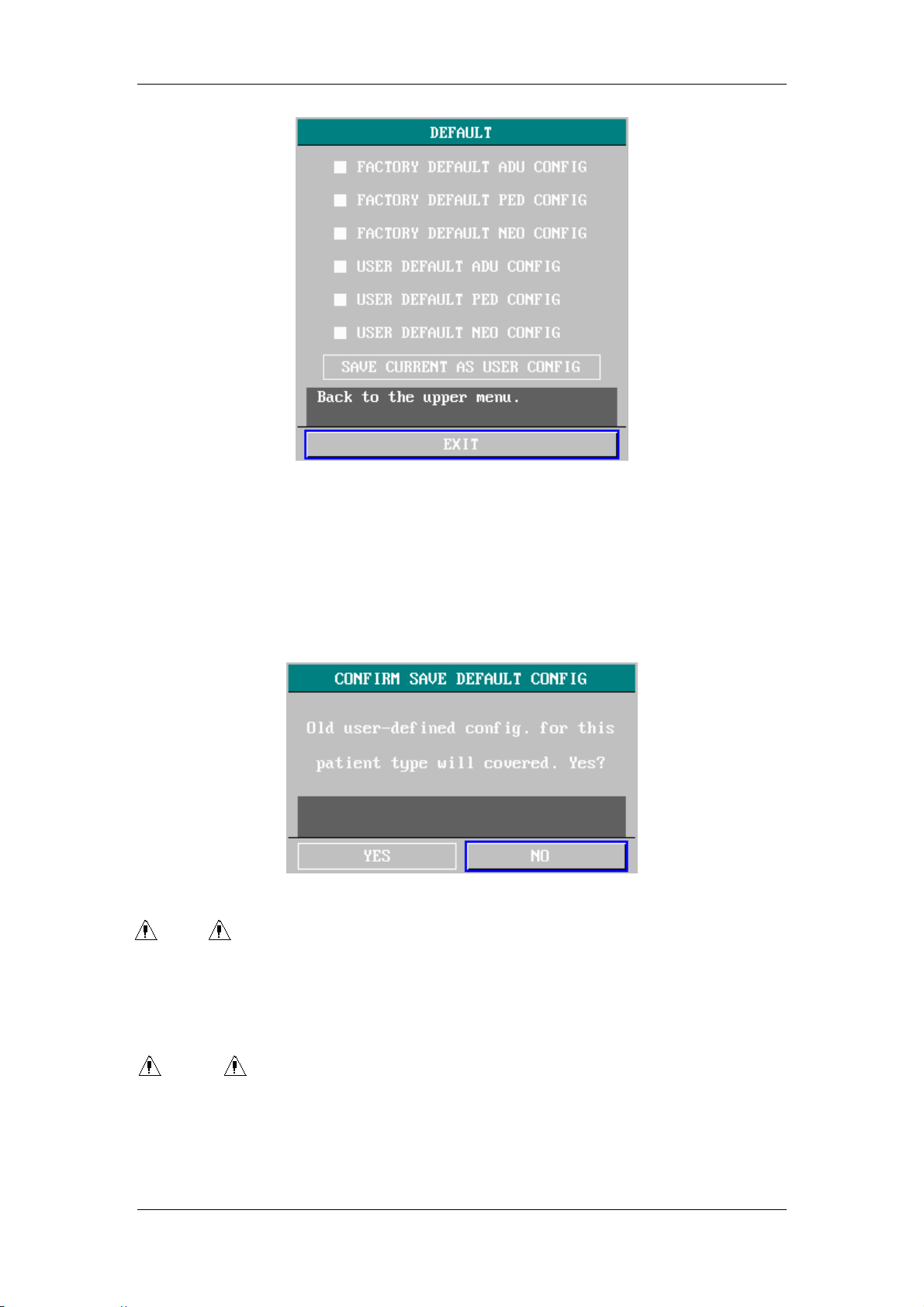
3.2 Default Setup
Note
After selecting any item in this sub-menu, the selected item will replace the current
setup of the system and accordingly become the system default configuration.
3-3
System Menu
Figure 3-4 DEFAULT Menu
In this sub-menu, you can select both the factory default and the user-defined default. Also in
this sub-menu, you can save the current system configuration as the user-defined default
configuration. But at this time, the system will automatically save all the setups in the
parameter menu, ECG gain and filter way as the user-defined default configuration according
to the patient type. Also, the dialog box as shown below will pop up.
Figure 3-5 CONFIRM DEFAULT CONFIG
Note
After selecting any item in the DEFAULT menu and exiting the box, the “CONFIRM
DEFAULT CONFIG” Dialog box will pop up, in which you can select [YES] to confirm
your selection or [NO] to give up your selection.
Warning
All configurations in the system will be replaced by “default configurations”.
3-4
System Menu
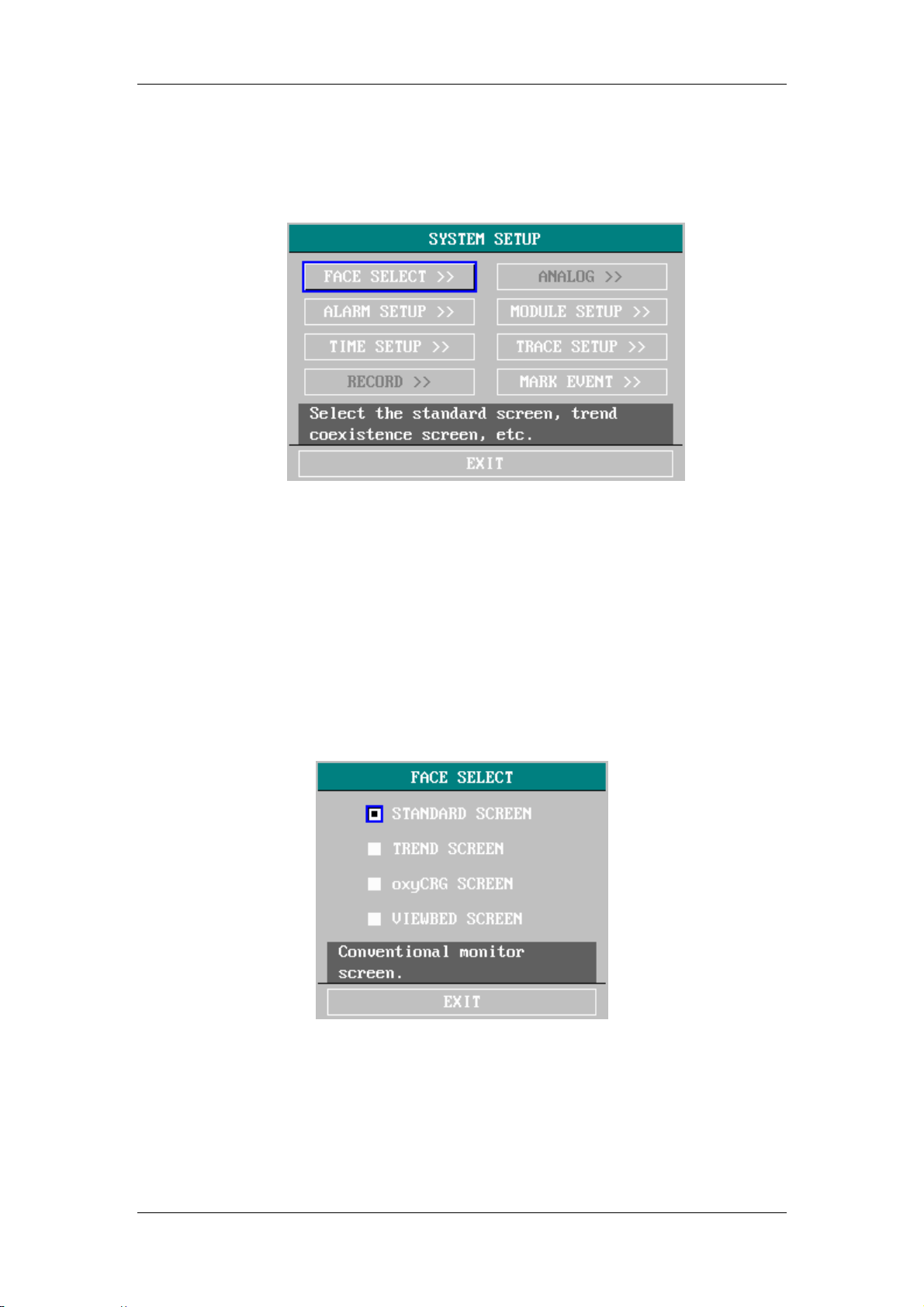
3.3 System Setup
Select the [system setup] item in the [system menu]:
Figure 3-6 System setup
In the [System setup] menu , users can setup the following items.
3.3.1 Face select
Select “FACE SELECT” item in “SYSTEM SETUP” menu to access “FACE SELECT” dialog
box as shown below, in which four selections are available: STANDARD SCREEN, TREND
SCREEN, oxyCRG SCREEN and VIEWBED SCREEN. Only one selection can be chosen for
each time.
Figure 3-7 FACE SELECT
3.3.2 Alarm setup
The system provides three levels of alarm volume. You can select any of them as per the
clinical requirement. The procedures are:
3-5

System Menu
Select the [ALARM SETUP] item in the “SYSTEM SETUP” sub-menu of the “SYSTEM
SETUP” menu. The menu as shown below will pop up, in which you can set up the alarm
volume and other alarm information. For detailed information, refer to Chapter Alarm.
Figure 3-8 Alarm Setup
Pick “ALARM VOL” item, turn the knob to set the volume. The options are from “10” to “1”.
“10” indicates the maximum volume while “1” the minimum.
"Multilevel Volume" function, only three options are available for volume, “3”, “2” and “1”.
If your machine does not have
3.3.3 Time Setup
Select the [TIME SETUP] item in the “SYSTEM SETUP” menu. The menu as shown below
will pop up. System time is in the format of year, month, day, hour, minute and second. Use
cursor to highlight the item that you want to modify and turn the knob to select time. Then
select [EXIT].
Note
You shall set up the system time upon turning on the monitor (if you need to set up the
system time); otherwise, when you review the content with time information, the
system may not display the correct time.
3-6

System Menu
Figure 3-9 System Time Setup
When this monitor is linked to the Central monitor system, its system time will keep consistent
with that of the Central monitor system. Method to adjust time:Once link is successfully
established, the Central monitor system will send its current time to the monitor. The monitor
will automatically adjust its system time accordingly. Besides, the Central monitor system will
keep on sending its current time to the monitor once per hour to maintain consistent time
between them. However, the monitor will not adjust its time if it is different from the Central
monitor system only in second. Please note that if you are setting up the system time when
link is just established successfully, the monitor will immediately close the setup menu of
system time. The setup button of system time in the system setup menu is disabled when the
monitor is linked to the Central monitor system. That means you cannot open the setup menu
of system time. (If the Central monitor system has no this function, you can skip over this
paragraph.)
3.3.4 Recorder setup
Select the [RECORD] in the “SYSTEM SETUP” menu to call up the following menu:
3-7

System Menu
Figure 3-10 Recorder Setup
In this menu, the user can set up to output two waveforms. The waveforms that can be
selected include:
ECG1ECG6
SPO2
IBP
there are six ECG waveforms in multi-leads display (If no ECG waveform is
currently displayed on the screen, this item cannot be picked).
SpO2 Plethysmogram.
The IBP waveform on the screen (If no IBP waveform is currently displayed on
the screen, this item cannot be picked).
RESP
RESP waveform (If no RESP waveform is currently displayed on the screen,
this item cannot be picked,).
OFF
No display for this waveform.
RT REC TIME this item has two options, CONTINUAL and 8s. “CONTINUAL” means
once pushing the “REC/STOP” button on the recorder panel or the monitor panel, the
recorder will continuously print out the waveform or parameter until this button is pushed
again.
TIMING REC TIME used to set up the time interval between two recordings. 10 selections
are available: “OFF, 10min, 20min, 30min, 40min, 50min, 1hour, 2hours, 3hours and
4hours”. The system will start the recording process according to the selected time
interval. The recording time is always 8 seconds.
Note
RT REC TIME takes priority over TIMING REC TIME.
REC RATE: this item has two options, 25.0 and 50.0 mm/s.
REC GRID: used to decide output format: OFF is without grid, and ON is with grid.
CLEAR REC TASK: used to clear the alarm event that has been generated and is waiting
for recording out.
3-8
System Menu
Note
If two same waveforms are selected, the system will automatically change one of the
waveform to a different one.
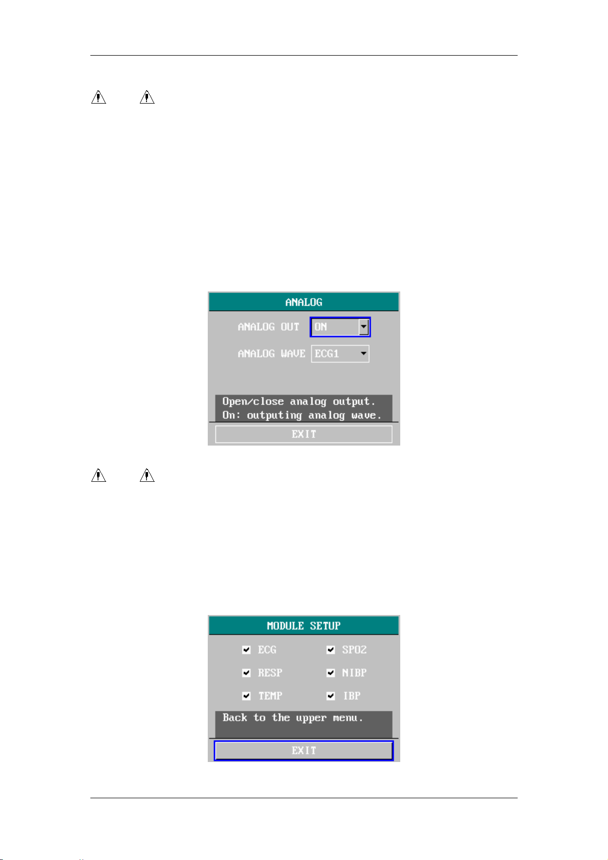
3.3.5 Analog
The monitor can output an analog waveform, whose time delay is less than 30ms. The output
terminal is on the rear panel.
Select “ANALOG” item in “SYSTEM SETUP” menu to call up the ANALOG menu. The first
item is for setting up On/Off of the switch of the analog output. The second item is for
selecting the waveform name to be output.
Select “EXIT” item to return to the previous menu.
Figure 3-11 ANALOG
Note
In the USER MAINTAIN menu, If the AUX OUTPUT item being selected with NURSE
CALL, the AUX OUTPUT port will be used to realize NURSE CALL function while
“ANALOG OUT” function is switched off at the same time.
3.3.6 Module Setup
Select the [MODULE SETUP] item in the “SYSTEM SETUP” menu to call up the following
menu:
Figure 3-12 Module Setup
3-9

System Menu
You can choose the parameters to be monitored in this menu. This can avoid the interference
from the parameters that need not attention.
3.3.7 Tracing Waveforms Selection
Select the [TRACE SETUP] in the “SYSTEM SETUP” menu to call up the following menu.
Figure 3-13 Tracing Waveforms Selection
You can define the traces displayed on the screen in this menu. The waveforms available for
selection are those whose modules have been selected in “MODULE SETUP” menu.
This user can only decide the display sequence of the waveforms on the screen. Select the
“WAVE SEQUENCE” item in the menu to access the sub-menu of the same name as shown
in the figure below.
Figure 3-14 Wave sequence
3.3.8 Event Setup
The monitor has four types of events. You can specify their representations by yourself.
Select the [MARK EVENT] item in the “SYSTEM SETUP” to call up the following menu:
3-10

System Menu
Figure 3-15 MARK EVENT Menu
How to mark the event: Use the rotary knob to select one from event A, B, C and D. The @
symbol will appear in the frame of the event being selected. Once making a wrong selection,
you can push the knob on the event again to give up the selection. Select [EXIT] to exit the
menu and consequently the selection will come into effect.
Event function has following significance:
To classify the records into different categories, such as those having influence on patients
and those having influence on parameter monitoring including dose taking, injection, therapy
status. Event will be displayed on the trend graph/table in order to assist the analysis on the
patient parameters when the event happens.
3-1 1

System Menu
3.4 Selection Setup
Select the [SELECTION] item in the “SYSTEM MENU” to call up the following menu.
Figure 3-16 Selection Setup
KEY VOL:
Pick “KEY VOL” item in “SELECTION” menu, turn the knob to set the volume. The options are
from “10” to “0”. “10” indicates the maximum volume while “0” indicates close the volume. If
your machine does not have "Multilevel Volume" function, only four options are available for
volume, “3”, “2”,”1” and “OFF”.
HELP:
The system provides On-line Help to menu operations. You can choose any help information
as per your need. The method is:
Select the [SELECTION] item in the “SYSTEM MENU” to access the “SELECTION”
sub-menu, in which you can highlight the [HELP] item and turn the knob to select “ON” or
“OFF”. When it is “ON”, you can browse the on-line help information. When it is “OFF”, the
system will turn off the on-line help function.
SCAN TYPE:
The system can display all waveforms about monitored patient on the screen either in
“Refresh” or “Scroll” way. The method is:
Select “SELECTION” item in “SYSTEM MENU” to access “SELECTION” sub-menu, in which
there is the item “SCAN TYPE”. The user may decide the way to display the waveform by
choosing either “REFRESH” or “SCROLL”.
ALM LIMIT:
The system can display the alarm limits. You can choose this function as per your need. The
method is:
Select the [SELECTION] in the “SYSTEM MENU” to call up the “SELECTION” menu. You can
set the “ALM LIMIT” switch to “ON” or “OFF”.
3-12

System Menu
3.5 Monitor Version
Select the [VERSION] item in the “SYSTEM MENU” to know the software version of the
monitor.
Figure 3-17 Monitor Version
Select the [DEVICE CONFIG LIST] to know the configuration of the monitor.
Figure 3-18 Device Configuration List
3.6 Drug Calculation
You can use the drug calculation and titration table function to calculate the concentration of
15 kinds of drugs. For detailed information, please refer to Chapter: Drug Calculation and
Titration Table.
3-13

System Menu
3.7 Maintenance
Select the [MAINTAIN] item in the “SYSTEM MENU” to call up the “ENTER MAINTAIN
PASSWORD” dialog box as shown below, in which you can enter password and then
customize maintenance settings.
Figure 3-19 Enter Maintain Password
You cannot execute factory maintenance function, which is only available for the service
engineers of our company.
Input the password into the “ENTER MAINTAIN PASSWORD” box and press [CONFIRM], the
“USER MAINTAIN” menu will pop up, in which you can set up following items.
Figure 3-20 User Maintain
3-14

System Menu
For the [LANGUAGE] language, you can select the screen language you need.
For the [AUX OUTPUT] item, there are two options available:
■ ANALOG
OUT: if being selected, the AUX OUTPUT port will be used to realize
“ANANOG OUT” function while NURSE CALL function is switched off at the same time.
And visually the “NURSE CALL SETUP” item in “USER MAINTAIN” menu will become
gray indicating that the function is disabled.
■ NURSE CALL:
if being selected, the AUX OUTPUT port will be used to realize NURSE
CALL function while “ANALOG OUT” function is switched off at the same time.
For the [LEAD NAMING] item, you can select “AHA” or “EURO”. To know the difference
between these two styles, refer to Chapter: ECG/RESP Monitoring.
For the [ALM SOUND] item, you can set the alarm volume to “ON” or “OFF”.
For the [NET TYPE] item, two selections are available: HYPER III and CMS.
For the [LOCAL NET NO] item, it refers to the net No.
Warning
When the alarm volume is set to “OFF”, you will not hear the alarm sound if new alarm
occurs. Therefore, you must be very careful in using this selection.
If setting the alarm volume to “OFF” when the system is in Silence or Pause status, the
system will automatically discharge Silence or Pause status.
If you select “Silence” or “Pause” when the alarm volume is set to “OFF”, the system
will restore the alarm volume before the alarm volume is set to “OFF” and enter Silence
or Pause status.
Note
After the alarm volume is set to OFF, a
symbol w ill appear in the Technical Alarm
Area.
Note
Setting Alarm Volume to “OFF” is valid only when the monitor is turned on for this time.
After turning on the monitor next time, this setup will restore its value of the previous
time when the system is turned on.
COLOR SELF-DEFINE: is used by the user to define the color of the waveform displayed on
the screen. Five colors can be chosen from: green, cyan, red, yellow and white.
3-15

System Menu
Figure 3-21 Color Self-define
NURSE CALL SETUP: If the NURSE CALL item in AUX OUTPUT being selected, the NURSE
CALL SETUP submenu will be available.
Figure 3-22 Nurse Call Setup
SIGNAL DURATION: “PULSE” and “CONTINUUM” two types of signals are available.
Selecting “PULSE” indicates that the NURSE CALL is the pulse signal of 1s duration;
selecting “CONTINUUM” indicates that the NURSE CALL signal is synchronous with the
alarm signal designated in the triggering condition.
SIGNAL TYPE: “NORMAL OPEN” or “NORMAL CLOSE”.
NORMAL OPEN: select this item when the CALL system of the hospital is set to
“NORMAL OPEN”;
NORMAL CLOSE: select this item when the CALL system of the hospital is set to
“NORMAL CLOSE”.
ALM LEV and ALM TYPE: after NURSE CALL function is activated, the monitor provides
the following combination options of alarm level and alarm type for the user to choose in
order to trigger NURSE CALL signal. “ALM LEV” provides three combination options, i.e.,
NURSE CALL signal will be triggered when it is “HIGH” alarm, “MED” alarm or “LOW”
3-16

System Menu
alarm. “ALM TYPE” provides two combination options, i.e., NURSE CALL signal will be
triggered when it is “TECH” alarm or “PHYS” alarm.
Warning
When no option in “ALM TYPE” is selected, the NURSE CALL signal will not be
triggered in whatever condition.
Warning
When in ALARM SILENCE/PAUSE status, the monitor will automatically switch off
NURSE CALL signal; after discharging ALARM SILENCE/PAUSE status, the monitor will
automatically return to the status before ALARM SILENCE/PAUSE is activ ated.
If the user select “CLOSE” in the ALARM SOUND item of the “USER MAINTAIN” menu,
it will does not affect the function of NURSE CALL.
Warning
The nurse call feature should not be used as the primary source of alarm notification.
The audible and visual alarms of the monitor, used in conjunction with clinical signs
and symptoms, are the primary source for notifying medical personnel that an alarm
condition exists.
3-17

System Menu
3.8 DEMO function
Select the [DEMO] item in the “SYSTEM MENU” to call up the “ENTER DEMO PASSWORD”.
After entering the password, the system enters DEMO status.
The purpose of waveform demonstration is only to demonstrate the machine performance,
and for training purpose. In clinical application, this function is not forbidden because the
DEMO will mislead the medical staff to treat the DEMO waveform and parameter as the
actual data of the patient, which may result in the delay of treatment or mistreatment.
Therefore before entering this menu, you shall enter password.
Figure 3-23 Input Demo Key
3-18

Chapter 4 Face Select
This monitor has four different operating screens, which are “Standard Screen”, “Trend
Screen”, “oxyCRG Screen”, and “Viewbed Screen”. When required, you can select
different operating screens for necessary information. Let’s probe into these
operating screens one by one.
4.1 Select Operating Screen
In the “SYSTEM MENU”, select the “FACE SELECT” option in the “SYSTEM SETUP”
menu to call up the dialog box as shown in the figure below. There are four options in
this dialog, which are “STANDARD SCREEN”, “TREND SCREEN”, “oxyCRG
SCREEN” and “VIEWBED SCREEN”. Only one item can be selected at one time.
four
Figure 4-1 FACE SELECT
4.2 Standard Screen
In the “FACE SELECT” menu, Select the “STANDARD SCREEN” option to enter the
Standard Screen. The Standard Screen displays to us the parameters in the Parameter
area and the waveforms being monitored. This screen is the basic operating screen of
the monitor.
4-1

Face Select
Figure 4-2 STANDARD SCREEN
4.3 Trend Screen
Enter TREND SCREEN
In the “FACE SELECT” menu, select the“TREND SCREEN”option to enter the Trend
Screen.
Figure 4-3 TREND SCREEN
Position of trend graph
4-2

Face Select
Trend graph is located to the right of the corresponding waveform in the Waveform
area. Its color is the same as that of the corresponding parameter.
Trend length
Dynamic trend length is 2 hours. On the trend graph, the scale of the right end of the
X-axis is 0 hour while the left end is 2-hour .
Select trend parameter
If multiple parameters are located at the same position on the trend graph, by selecting
the corresponding hot key of a parameter on the trend graph, you can have the trend
graph of this parameter displayed on the screen. For example, in ECG trend graph,
you can select hot keys such as HR, ST or PVCs, then the system will display their
corresponding trend graphs respectively.
Close trend screen
In the “FACE SELECT” menu, select options of other operating screens to close the
Trend Screen.
4.4 oxyCRG Screen
Enter oxyCRG screen
In the “FACE SELECT” menu, select the “oxyCRG SCREEN” to enter the oxyCRG
Screen.
Figure 4-4 oxyCRG SCREEN
Trend graph of oxyCRG screen
Located at the lower part of the screen, oxyCRG screen consists of three trends: HR
4-3

Face Select
Trend, SpO2 Trend and RR Trend or Compressed Resp. Waveform.
Select OxyCRG trend length
Three are three hot keys at the bottom part of the oxyCRG Screen, which are
4MIN/2MIN/1MIN, RR/RESP WAVE, and REC.
By using hot keys for trend time, you may select to display trend graphs of three
different lengths, i.e., 1 min, 2 min and 4 min.
Select RR trend or Compressed Resp. Waveform
By using the hot keys for RR/RESP WAVE, you may select either RR trend graph or
compressed Resp. Wave. They occupy the same position. Therefore, if select “RR”,
the position displays the dynamic trend of RR. If select “RESP WAVE”, the position
displays the compressed Resp. Wave.
Record
Select the “REC” hot key in the “OxyCRG Screen”, you may use the recorder to output
the three waveforms in the oxyCRG at the same time.
Close OxyCRG
In the FACE SELECT menu, select options of other operating screens to close the
OxyCRG Screen.
4.5 Viewbed Screen
If another monitor is connected on the same LAN of this monitor, you can use this
monitor to view any measured waveform and information about all measured
parameters from another monitor.
Enter Viewbed Screen
Select the “VIEWBED SCREEN” option in the “FACE SELECT” menu. Viewbed
Screen window occupies the space of the bottom four waveforms.
4-4

Face Select
Figure 4-5 VIEWBED SCREEN
Hot key of Viewbed
There are two hot keys in the Viewbed Screen: Select Bed Number and Select
Waveform.
The hot key of Select Bed Number displays the bed numbers and patient names of
other monitors currently connected on the LAN. You can select a monitor to be
monitored according to the patient name and bed number. If at this time no other
monitors are connected on the same LAN of this monitor, the hot key of Bed Number
will therefore display “N/A”. After you use this hot key to select a monitor to be viewed,
the system will toggle to the display of the selected monitor for your view. The selected
waveform is one of those listed in the hot key of Select Waveform.
The hot key of Select Waveform is used to select a waveform generated by the
monitor being viewed. If the hot key of Select Waveform displays “N/A”, it indicates that
the bedside monitor being viewed has no waveforms. You can use this hot key to
select and therefore view different waveforms of the monitor being viewed.
Alarm indicator of Viewbed
On the upper right side of the Viewbed Screen, there is an Alarm Indicator used to tell
the alarm status of the monitor being viewed. The activity of this alarm indicator is
identical with that of the alarm lamp on the panel of the monitor being viewed. That is
to say, if the monitor being viewed occurs medium/low level alarm, this alarm indicator
illuminates yellow; if it occurs high level alarm, this alarm indicator illuminates red. If
the monitor being viewed has no alarm or the alarm is screened, the icon for this alarm
indicator will not be displayed.
Parameter area of Viewbed Screen
Under the hot key of Select Bed Number is the Parameter area, in which parameters
4-5

Face Select
of all monitors being viewed are displayed.
Waveform area of Viewbed Screen
Under the hot key of Select Waveform is the Waveform area. The Sweep manner
(refreshing or scrolling) of the waveform is identical with that of this monitor. The
feature description of the displayed waveform is given above the waveform. Sweep
speed is also identical with that set up for the same waveform on this monitor.
Technical Information area
Technical Information area is to the right of patient name in Viewbed Screen. This area
displays related technical information to Viewbed, such as due to network failure or
network too busy, Viewbed is disabled.
Close Viewbed Screen
In the FACE SELECT menu, select options of other operating screens to close the
Viewbed Screen.
Rules for automatically selecting monitor to be viewed and waveform
When you turn on the monitor or enter Viewbed Screen, the system will automatically
select a networked bedside monitor and a waveform of this monitor for you to view. If
the monitor being currently viewed is disconnected, the viewed monitor will
automatically close, clear displays of all alarms, parameters and waveforms. However
in this situation, the Viewbed Screen still displays. If you want to view another monitor,
you must select again through using hot keys.
If a measure module of the viewed monitor is plugged out or closed, its corresponding
waveform will disappear and the waveform in the Waveform area will not be refreshed.
Instead this Waveform area will display empty. At this time, if you want to vie w other
waveforms of this monitor, you need to select again.
4-6

Chapter 5 Alarm
This chapter gives general information about the alarm and corresponding remedies.
Alarm setup and prompt messages are provided in respective parameter setup sections.
Warning
When PM-8000 is powered on, the system may verify the audio and visual alarm
function.
Upon turning on the monitor, a “Dang” will be heard and at the same time the indicator
will flash twice in yellow and red. This is used to verify the audio and visual alarm
function of the system. Therefore, the user should be carefully observe the status. If
the audio and visual alarm function is not normal, it indicates that the monitor cannot
be used to monitor a patient. Please contact Mindray Company or service center.
5.1 Alarm Modes
5.1.1 Alarm Level
Each alarm, either technical or physiological, has its own level. For alarm of higher level,
when it occurs, the system will give prompt in a more alert way. Some alarm’s level can be set
by the user via software. Others can not be changed once defined by the system. Alarms in
PM-8000 are divided into three levels, that is, high, medium and low.
High-level alarm indicates the patient’s life is in danger or the monitor under using has serious
problem in technical respect. It is the most serious alarm.
Medium-level alarm means serious warning.
Low-level alarm is a general warning.
Alarms are classified into three categories, which are physiological alarm, technical alarm and
general alarm. Physiological alarm refer to those alarms triggered by patient’s physiological
situation which could be considered dangerous to his or her life, such as heart rate (HR)
exceeding alarm limit (parameter alarms). Technical alarm refer to system failure which can
make certain monitoring process technically impossible or make monitoring result
unbelievable. Technical alarm is also called System Error Message. General alarm belongs to
those situations that can not be categorized into these two cases but still need to pay some
attention.
5-1

Alarm
PM-8000 has preset the alarm level for the parameters. You can also modify the alarm level
using the method described in this chapter.
Alarm level of the System Error Message (technical alarm) is pre-set in the system.
All technical alarm level and general alarm level, some of the physiological alarm level are
pre-set in the system and can not be changed by user.
5.1.2 Alarm Modes
When alarm occurs, PM-8000 may raise the user’s attention in at least three ways, which are
audio prompt, visual prompt and description. Audio and visual prompt is given by TFT display
device, the speaker on the display device and the alarm indicator. Description is displayed on
the screen. Physiological alarm is displayed in the Physiological Alarm area. Most of technical
alarms are displayed in the Technical Alarm area. Technical alarms related to NIBP
measurement are displayed in the NIBP Technical Alarm area at the bottom of NIBP
parameter area.
Note
The Physiological Alarm area is on the upper right part of the screen. The Technical
Alarm area is to the left side of the Physiological Alarm area.
Note
The concrete presentation of each alarm prompt is related to the alarm level.
Alarm prompt of the parameter exceeding the alarm limit.
When physiological alarm of the monitored parameter exceeds the alarm limit, besides using
the above-mentioned three ways to give the alarm prompt, the monitor also gives alarm by
making the monitored parameter flash in the frequency of 1Hz. If at this time the upper and
lower limits of the parameter are displayed, they will flash in the same frequency (1Hz).
Screen Display
When an alarm occurs, the parameter triggering the alarm flashes. “*” signal appears on the
screen indicating the occurrence of alarm. Red “***” indicates high-level alarm, yellow “**”
indicates medium-level alarm, and yellow “*” indicates low-l evel alarm. Technical alarm will not
prompts “*” signal.
Lamp light
The high/medium/low-level alarms are indicated by the system in following different visual
ways:
5-2

Alarm
Alarm level Visual prompt
High Alarm indicator flashes in red with high frequency.
Medium Alarm indicator flashes in yellow with low frequency.
Low Alarm indicator lights on in yellow .
Alarm Sound
The high/medium/low-level alarms are indicated by the system in following different audio
ways:
Alarm level Audio prompt
High
Medium Mode is “DO-DO-DO”, which is triggered once every 24 seconds.
Low Mode is “DO-”, which is triggered once every 24 seconds.
Mode is “DO-DO-DO------DO-DO, DO-DO-DO------DO-DO”, which is
triggered once every 8 seconds.
Note
When alarms of different levels occur at the same time, the monitor prompts the one of
the highest level.
Alarm Setup
The setup of the alarms can be realized in the alarm menu.
Press the “ALARM SETUP” button on the SYSTEM SETUP menu to call up “ALARM SETUP”
menu (default menu) as shown below. In the “ALM SEL” item, the user may set up the
information about common alarm setup (represented by “COMMON ALM SETUP”) and the
alarm setup of each parameter.
Figure 5-1 ALARM SETUP
5-3

Alarm
COMMON ALM SETUP
Select “COMMON ALM SETUP” selection in “ALM SEL” item. This operation may call up the
dialog box as the default one.
ALARM VOL: The options are from “10” to “1”. “10” indicates the maximum volume while
“1” the minimum.
are available for volume, “3”, “2” and “1”.
ALM REC TIME: which has three selections: 8S, 16S, 32S.
ALM PAUSE TIME: refers to the alarm suspension time span, which has three selections:
1MIN, 2MIN, 3MIN.
PARA ALM TYPE: which has two selections: LATCH, UNLATCH. LATCH refers to the
situation once alarm occurs, the system will alarm always until the intervention of the
operator (press SILENCE on the panel). UNLATCH refers to the situation that once the
alarm condition is discharged, the alarm will disappear automatically.
Alarm setup of each parameter
In “ALARM SETUP” menu select “ALM SEL” item to set up the alarm information of following
parameters. They are HR, ST, PVC, SPO2, NIBP, IBP (1, 2), RESP, TEMP. For example:
Method to set up alarm information of HR:
Step 1: Select “HR ALM SETUP” in “ALM SEL” item to call up the dialog box “ALARM
SETUP” for HR only.
Step 2: Five items are available for the user to set up, which are HR ALM (on/off of the alarm
switch), ALM LEV(alarm level), ALM REC(alarm recording switch), ALM HI (higher limit of HR
alarm), ALM LO (lower limit of HR alarm). When use the knob to select each item and press
the knob, a pull-down list appears for the user to choose his desired selection.
The method for setting the alarm information of other parameters is the same as HR.
If your machine does not have "Multilevel Volume" function, only three options
5.2 Alarm verification during power on
During PM-8000 power on, audible and visual alarm capability will be tested by the system.
Every time when PM-8000 powers on, alarm beeps “DO-”, and the LED indicator on the
display device flashes. If no beeps heard or no alarm indicator flashing viewed, do not use
this device to monitor any patient, and notify Customer Service Center.
5.3 Alarm Cause
Alarm occurs when:
1.Physiological alarm is evoked;
2. Alarm for error of the system (technical alarm) is evoked;
3. General alert occurs.
5-4

Alarm
A. Conditions that activate the parameter alarms:
When the measurement value exceeds the alarm limit and the alarm is set “ON”. Alarm will
not activate if the alarm is set “OFF”.
B. Conditions that activate the system alarms (technical alarm):
Upon the system error, the monitor prompts alarm immediately and proceeds corresponding
remedy, stops all monitoring and eliminates the final results in order to avoid faulted treatment.
If more than one error occurs, they will be displayed by turns.
C. General alert
In some circumstances, alerts will behave as physiological alarm but in normal sense, we
don’t regard them as real patient health related items.
5.4 SILENCE and PAUSE
SILENCE/CLOSE
Push the SILENCE button on the panel for more than 1 second, the system will shut off all
sounds. Push the SILENCE button again, the system can exit the SILENCE status and
restore the PAUSE status and accordingly suspend the alarm as per the previously defined
time duration. Push the SILENCE button for the third time, the system will exit the PAUSE
status and restore the normal alarm status by giving the alarm sound again. When the system
is in the SILENCE status, any new alarm will terminate the SILENCE status and make the
system restore the normal alarm status.
Note
When the
accordingly the system will not give alarm sound. Therefore, you must be very careful
in using this function. There are two methods to terminate this status. One is to set the
alarm volume to “ON” in the MAINTAIN menu. The other method is to push the
SILENCE button shortly to make the
symbol appears indicating the alarm sound is shut off and
symbol become ; push the SILENCE
button again and the system will restore the normal alarm status again.
PAUSE
Push the SILENCE button on the panel shortly, the system will shut off all alarm sound and
visual prompt as well as description of physiological alarm, and enter the PAUSE status. The
countdown of PAUSE status is displayed in the Physiological Alarm area, in which area the
symbol is also displayed.
The time duration of the PAUSE status can be set to 1min, 2min or 3min. You can select in
5-5

Alarm
the [ALM PAUSE TIME] item in the “SYSTEM MENU\SYSTEM SETUP\ALARM SETUP”.
After pushing the SILENCE button again, the system will restore the normal status. Besides,
the occurrence of any new technical alarm will also terminate the PAUSE status and let the
system restore the normal status. The
Note
After the system goes back to the normal status, the existence of alarm depends on
whether the alarm condition is complied with. After pushing the SILENCE button, the
system will permanently shut off the alarm sound for LEAD OFF/SENSOR OFF alarm.
symbol disappears, too.
5.5 Parameter Alarm
The setup for parameter alarms is in their menus. In the menu for a specific parameter, you
can check and set the alarm limit, alarm status. The setup is isolated from each other.
When a parameter alarm is off, a symbol “
are turned off individually, they must be turned on individually.
For the parameters whose alarm is set to ON, the alarm will be triggered when at least one of
them exceeds alarm limit. The following actions take place:
1. Alarm message displays on the screen as described in alarm mode;
2. The monitor beeps in its corresponding alarm class and volume;
3. Alarm lamp flashes;
4. Store all parameter values during the alarm and 4,8 or 16 second waveform prior to and
after alarm.
5. If alarm recording is on, the recorder starts alarm recording. For further information on
alarm recording, please refer to Chapter Recording.
” displays near the parameter. If the alarms
5-6

Alarm
5.6 When an Alarm Occurs
Note
When an alarm occurs, you should always check the patient's condition first.
The alarm message appears at the top of the screen on the right side. It is needed to identify
the alarm and act appropriately, according to the cause of the alarm.
1. Check the patient's condition.
2. Identify the cause of the alarm.
3. Silence the alarm, if necessary.
4. When cause of alarm has been over, check that the alarm is working properly.
You will find the alarm messages for the individual parameter in their appropriate parameter
chapters of this manual.
5-7

FOR YOUR NOTES
Alarm
5-8

Chapter 6 Freeze
General
Freeze & Unfreeze
Review & Record Frozen Waveforms
6.1 General
When monitoring a patient, you may freeze the waveforms of interest so as to view them
carefully. Generally you can review maximally 40 seconds of a frozen waveform. If required,
you may also use recorder to print out a frozen waveform. The Freeze function of this monitor
has following features:
Freeze status can be activated on any operating screen;
At the same time of entering the Freeze status, the system exits all other operating
menus. Besides, the system freezes all waveforms in the Waveform area of the Basic
Screen, or Full-lead ECG waveforms and the extra waveform (if available) on the
Full-lead ECG screen. Nevertheless the Parameter area refreshes normally.
In the Freeze status, it does not affect the display and refresh of the Trend Graph
area on the trend screen, the display and refresh of oxyCRG on the Dynamic Refresh
screen, or the display and refresh of the Viewbed window on the Viewbed screen.
The frozen waveforms can be reviewed or recorded.
6.2 Enter/Exit Freeze Status
Enter Freeze Status
In the Non-Freeze status, press the “FREEZE” button on the front panel of the monitor to let
the system exit the Menu being currently displayed (if available), then enter the Freeze status
and display the popup “FROZEN” menu. In the Freeze status, except Viewbed waveforms, all
other waveforms are frozen. In other words, the system will no longer refresh all other
waveforms.
Exit Freeze Status
In the Freeze status, executing any of the following operations will command the system to
exit the Freeze status:
Select the “EXIT” option on the “FROZEN” menu;
Press the “FREEZE” button on the front panel again;
6-1

Freeze
Press the non-immediate-to-execute button (such as a button once pressed, a
menu will pop up for you to further select an option )on the front panel and system
buttons of MAIN and MENU;
Execute any operation that may trigger the adjustment of the screen or display of
a new menu.
After exiting the Freeze status, the system will discharge the Freeze status, clear
screen waveforms and resume to display real-time waveforms. In the Screen Refresh
mode, the system begins scanning waveforms from the extreme left one. In the Screen
Scroll mode, the system begins displaying and scrolling waveforms from the extreme
right one.
6.3 FROZEN Menu
Press the “FREEZE” button on the button module, the FROZEN menu will appear on the
bottom part of the screen. At the same time, the system enters the Freeze st atus.
Figure 6-1 FROZEN menu
WAVE 1: used to select the first frozen waveform to record. The
pull-down list of this item gives you the names of all frozen waveforms
displayed on the screen.
WAVE 2: used to select the second frozen waveform to record. The
pull-down list of this item gives you the names of all waveforms displayed
on the screen.
RECALL:used to review frozen waveforms.
REC: after selected, the system begins recording the frozen waveforms
selected in“WAVE 1” and“WAVE 2”.
EXIT: after pressed, the system closes the FROZEN menu and exits
the Freeze status。
Note
Pressing the “FREEZE” button repeatedly in short time period may result in
discontinuous waveforms on the screen.
6.4 Reviewing Frozen Waveform
6-2

Freeze
By moving the waveform, you may review a waveform of 40 seconds before the moment
when it is frozen. For a waveform less than 40 seconds, the remaining part is displayed as a
straight line. Use the rotary snob on the front panel to move the cursor to the “RECALL”
option on the FROZEN menu. Press the knob, the option displays “L-RIGHT”. By turning the
knob left or right, frozen waveforms on the screen will move left or right correspondingly.
There is an arrow indicating upward under the right side of the last waveform. There is also a
time scale beside the arrow. “0S” is used to mark the moment when waveforms are frozen.
With waveforms moving right, this time mark will in turn change into -1S, -2S, -3S… These
time marks are applied to all waveforms on the screen.
6.5 Recording Frozen Waveform
In the Freeze status, you may output displayed frozen waveforms via the recorder. Maximum
2 waveforms can be output at one time. On the FROZEN menu, the pull-down lists of both
“WAVE 1” and “WAVE 2” give you all names of frozen waveforms on the screen, from which
you may select two. Select the “REC” option on the FROZEN menu to output parameters
generated upon the freezing moment and the two selected frozen waveforms. If one of the
two selected waveforms is closed or not available, only parameters and the other waveform
are recorded. If these two selected waveforms are all closed or not available, only parameters
are recorded. As for the function of recording frozen waveforms, you can only record the
waveforms displayed upon the freezing moment. The recording time length is the same as the
length of the waveform displayed on the screen. For example, if the speed of a waveform is
relatively fast, then it needs shorter time to record it. When recording frozen waveforms, the
system is still in the Freeze status. After completion of recording, if required, you may select
once more the waveform to be output and select “REC” option again to record the whole
selected waveforms. If the recorder does not exist, selecting the “REC” option can only call
out the prompt “Recorder does not exist” in the STATUS bar. For more detailed information
about recording, please refer to the chapter of “Recording”.
6-3

FOR YOUR NOTES
Freeze
6-4

Chapter 7 Recording
General information on recording
Instructions for configuring and recording
Recording messages
7.1 General Information on Recording
A thermal dot matrices recorder with 48mm wide printout paper is used for PM-8000 Portable
Patient Monitor.
Performance of the Recorder
Waveform record is printed out at a rate of 25 or 50 mm/s.
It can record up to 2 waveforms.
Output with grid selectable.
English / Chinese printout.
The real time recording time and waveform are user-configurable.
Auto recording interval is set by the user, the waveform is in accordance with the real
time recording.
The alarm recording waveform is automatically selected by the monitor.
7.2 Recording Type
PM-8000 provides several stripe recording types:
Continuous real-time recording
8 second real-time recording
Auto 8 second recording
Alarm recording
Waveform freeze recording
Trend graph/table recording
ARR events review recording
Alarm event recording
NIBP review recording
Monitor information recording
Drug calculation titration recording
OxyCRG recording
7-1

Recording
Real-time Recording
Real-time recording starts as you press the REC/STOP button on the recorder.
The waveforms for continuous real-time recording and continuous 8 second recording are
automatically set by the monitor (usually the first two waveforms displayed on the screen).
You can also configure it through the menu. Refer to related section for details.
In RECORD menu, the user can choose two waveforms to be printed out. The User can setup
one waveform off. Thus, the real time record will print out one waveform. If two waveforms are
off, the real time record will print out measure parameters only.
Note
If certain recording is in process, and another parameter demands alarm recording, it
will only be executed after the earlier recording is finished.
Auto recording
The monitor starts the recorder for 8 seconds according to interval time set in the “TIMING
REC TIME” of the “RECORDER ” menu. Refer to Chapter 3.5 Recorder Setup for details.
Alarm Recording
Parameter Alarm
The monitor records waveforms 4, 8, or 16 seconds prior to and after the alarm (totally 8, 16
or 32 seconds) (which can be selected in System Menu). All parameter values during the
alarm will also be recorded.。
When parameter alarm occurs, two recorded waveforms can be printed out.
In order to avoid repeated printout of alarm waveforms:
If more than two parameter alarms are switched on and triggered simultaneously, the
recorder will print out those of the highest level. If of the same alarm level, the latest
alarm will be printed out.
If an alarm occurs during the alarm of another parameter, it will be printed out after the
current recording is finished.
If many alarms occur at the same time, some of waveforms will be stored for printout in
turn.
ST Segment Alarm
The monitor records 2-channel ECG waveforms 4, 8, or 16 seconds prior to and after the
alarm (totally 8, 16, or 32 seconds) (which can be selected in the ECG SETUP menu). All
parameter values during the alarm will also be recorded.
7-2

Recording
Arrhythmia Alarm
The monitor records 2-channel ECG waveforms 4 seconds prior to and after the alarm (totally
8 seconds). All measurement results during the alarm will also be recorded.
Freeze Waveform Recording
The monitor prints out the selected waveforms under the FREEZE mode. In this way you can
snap the abnormal waveforms on the screen and record it.
Trend Graph / Table Recording
The monitor can print out the trend graph and table in the current TREND GRAPH or TREND
TABLE window.
Arrhythmia Review Recording
The monitor can print out the alarm Arrhythmia event in the current ARR RECALL window.
Alarm Review Recording
The monitor can print out the alarm events include waves and parameters in the current
ALARM RECALL window.
NIBP Review Recording
The monitor can print out all the NIBP review events in NIBP RECALL window.
Monitor Information
The monitor can print out messages in the current STATUS window.
Titration Table
The monitor can print out the messages in the current TITRATION window.
Notes on Recording
Recording texts:
Real time Report
Periodic Report
Para Alarm Report: XXX (name of the alarm parameter)
Arrhythmia Report: XXX (Arrhythmia type)
Freeze Wave Report
Trend Graph
Trend Table
Para Alarm Review
NIBP Test Review
Status Report
Titration Table
Alarm parameters, alarm time and freeze time
Patient bed number, name, sex, height, weight, date of birth, admission date
Parameter name and value
7-3

Recording
Recording time
Waveform name
Waveform scale (for ECG waveform)
ECG lead, scale, filter mode, (if having ECG waveforms, it will be printed out within the
first second or when changing the lead, gain and filter mode during real-time recording.)
IBP scale (the first second of IBP waveform)
CO2 scale (the first second of CO2 waveform)
Date and time
Company name
7.3 Recording Startup
You can start the recording in the following ways:
Continuous real-time recording Press REC/STOP to start/stop the recording.
8 second real-time recording Press REC/STOP to start recording. It will automatically
stop in 8 seconds.
Auto recording Record the two waveforms selected in RECORD menu
according to the setup time interval in RECORD menu.
Alarm recording When alarm recording is set ON, it automatically starts
when alarm occurs.
Frozen waveform recording ---After accessing FREEZE menu, use knob to select two
waveforms to be output. Then press REC button in the
menu to print out the waveforms.
If two waveforms are off, the measure parameters in frozen
are printed out only.
Trend graph recording Pick ”REC” button in the “TREND GRAPH” menu when
viewing the trend graph to print out the currently displayed
trend graph.
Trend table recording Pick ”REC” button in the “TREND TABLE” menu when
viewing the trend table to printout the currently displayed
trend table.
Arrhythmia review recording Access ARR RECALL window from ARR ANALYSIS of ECG
SETUP menu and Pick ”WAVE” button to access “ARR
WAVE RECALL” menu. Then press “REC” button to output
the Arr. Waveform and related information currently
displayed on the screen.
Alarm review recording Access the “ALARM RECALL” window from “ALARM
RECALL CONDITION” menu from “SYSTEM MENU” and
pick “REC” button to print out the alarm review waveform
7-4

Recording
and related information currently displayed in the “ALARM
RECALL” window.
NIBP review recording Access the “NIBP RECALL” window from “SYSTEM MENU”
and pick “REC” button to print out the NIBP information
currently displayed in the window.
Monitor information recording Access the “ENTER MAINTAIN PASSWORD” menu from
the “MAINTAIN” menu. Then pick the “STATUS” button to
access the ‘’STATUS” window. Pick “REC” button to print
out the status monitor information currently displayed in the
window.
Titration table recording Access the “DRUG CALC” menu from the “SYSTEM
MENU” menu. Pick the “TITRATION” button in the menu to
access the “TITRATION” window. Pick the “REC” button to
print out the titration currently displayed in the window.
OxyCRG recording In oxyCRG screen, pick the “REC” button to print out
oxyCRG currently displayed in the window.
Note
You can press REC/STOP button on the recorder to stop the current recording process.
Access the “RECORD” menu from the “SYSTEM SETUP” menu. Then pick the “CLEAR REC
TASK” button to stop all recording tasks.
7.4 Recorder Operations and Status Messages
Record Paper Requirement
Only standard 50 (+0/-1) mm thermosensitive record paper can be used, otherwise the
recorder may not function, the recording quality may be poor, and the thermosensitive
printhead may be damaged.
Function
■ When the recorder is working, the record paper goes out steadily. Do not pull the paper,
■ Do not operate the recorder without record paper.
Paper
When "RECORDER OUT OF PAPER" alarm is displayed, the recorder cannot start. Please
insert record paper properly.
Inserting Paper
■ Open the recorder catch.
■ Pull down the switch on the left axis of the recorder.
■ Insert a new roll of paper into the paper cassette, printing side facing the thermosensitive
Properly
or the recorder will be damaged.
Out
printhead.
7-5

Recording
■ When the paper can be seen from the other side, pull it out. Ensure proper position and
tidy margin.
■ Pull back the switch on the left axis of the recorder.
■ Give out the paper from the recorder outlet.
■ Close the recorder catch.
Note
Be careful when inserting paper. Avoid damaging the thermosensitive printhead.
Unless when inserting paper or shooting troubles, do not leave the recorder catch
open.
Removing Paper Jam
When the recorder functions or sounds improperly, open the recorder catch to check for a
paper jam. Removing the paper jam in the following way:
■ Cut the record paper from the feeding edge.
■ Pull up the switch on the left axis of the recorder.
■ Pull the paper from below.
■ Re-insert the paper.
Recorder Status Message (Technical Alarms)
Message Cause Alarm
RECORDER HEAD
HOT
REC HEAD IN
WRONG POS.
RECORDER OUT OF
The thermal terminal is
too hot.
The thermal head is not
in recording place. low
Record paper runs out.
PAPER
RECORDER COMM
Operating status error
ERR
RECORDER PAPER
JAM
RECORDER
INITIALIZING
TOO MANY REC
TASKS
RECORDER PAPER
W.P.
Recording continuously for
more than 30m
The recorder is in
initialization process.
Too many alarm events
take place simultaneously.
The paper is in wrong
position.
Level
low
low
low
low
low
Low
low
Remedy
Stop operation
Push down the switch on
the left axis of the
recorder.
Insert a new roll of
record paper.
Reset the recorder.
Re-insert paper.
Wait for the completion
of initialization
Send recording order
after a while.
Insert the record paper
again.
RECORDER BUSY
REC NOT AVAILABLE
In the status of printing out
Recorder stops working.
7-6
low
Low
Wait for the completion
of printing out
Gives recording order
after the recorder
restores to the normal

Recording
status or the failure is
removed.
RECORDER VLT
HIGH
RECORDER VLT LOW
RECORDER S. COMM
ERR
RECORDER
SELFTEST ERR
RECORDER INIT ERR
RECORDER INIT
ERR1
RECORDER INIT
ERR2
RECORDER INIT
ERR3
RECORDER INIT
ERR4
The voltage of the
recorder is too high.
The voltage of the
recorder is too low.
Unrecoverable serial port
communication error.
Possibly caused by the
RAM, ROM, CPU or
WATCHDOG.
Error occurs during
initialization
Error occurs during
initialization
Error occurs during
initialization
Error occurs during
initialization
Error occurs during
initialization
Low
Low
Low
Low
low
low
low
low
low
Stop recording until the
recorder restores normal
status.
Stop recording until the
recorder restores normal
status.
Shut down the monitor
and re-start it again.
Reset the recorder.
Shutdown and re-start
Shutdown and re-start
Shutdown and re-start
Shutdown and re-start
Shutdown and re-start
RECORDER INIT
ERR7
RECORDER INIT
ERR8
Error occurs during
initialization
Error occurs during
initialization
low
low
Shutdown and re-start
Shutdown and re-start
If after shutdown and re-start, error still exists, contact out service engineers.
7-7

FOR YOUR NOTES
Recording
7-8

Chapter 8 Trend and Event
PM-8000 provides 72-hour trend data of all parameters, storage of 400 NIBP measurement
results and 60 alarm events. This chapter gives detailed instruction for review of all data.
8.1 Trend Graph
The latest 1-hour trend is displayed every 1 or 5 seconds;
■
The latest 72-hour trend is displayed every 1, 5 or 10 minutes;
■
Pick "TREND GRAPH" in the SYSTEM MENU to call up the following menu:
Figure 8-1 TREND GRAPH Menu
The uppermost part is the name of the parameter, in which y-axis stands for value and x-axis
time. "
corresponding time displayed beyond the trend graph. Other trends except NIBP trend are
displayed as continuous curves. In NIBP trend graph, "u" indicates systolic value, "t"
indicates diastolic value, and "*" indicates mean value.
To select trend graph of a specific parameter:
Pick PARA SELECT item (the first selection of the upper line) and select a requested
parameter name by turning the knob.
" Indicates the value of the parameter, which it points to, is below the x-axis, with
8-1

Trend and Event
To select 1-hour or 72-hour trend graph:
Pick RESOLUTION item (the latter selection of the upper line), choose 1 or 5 sec for 1-hour
trend graph and 1, 5 or 10 min for 72-hour trend graph.
To view other trend curves:
When " " appears on the right part of the screen, pick "L-RIGHT" (the button at the
extreme left of the lower line), turn the knob clockwise to view later trend curves. When "
appears on the left part of the screen, pick the same item, turn the knob counterclockwise to
view earlier trend curve.
"
To change the display scale
Pick the “ZOOM” button in the lower line to adjust the y-axis scale and thus change the trend
curve in proportion. The value beyond maximum value will be represented by the maximum
value.
To obtain trend data of a specific time
The time to which the cursor points will change as the knob is turned. Parameter at this time
is displayed below the x-axis. When "
graph pages down for later trend curve as the cursor moves here. When "
the left part of the screen, the trend graph pages up for earlier trend curve as the cursor
moves here.
" appears on the right part of the screen, the trend
" appears on
To print out the trend curve
Press REC button to print out the trend curve of current selected parameter.
Mark event
If an event is marked A, B, C, or D, then the corresponding event type will display on the axis
time of the trend graph. The event sign (A, B, C or D) is displayed in a frame.
Operation example
To view the NIBP trend graph of the last 1 hour:
Pick the MENU hot key lower right of the screen.
Pick TREND GRAPH item.
Pick the first item and switch to NIBP by turning the knob.
Adjust the second item to be 1 or 5 sec.
Pick the ZOOM button and turn the knob to view changes of the trend graph time and
trend curve.
Stop at requested trend time section for careful review. Pick the ZOOM button to adjust
the display scale if necessary.
For measurement result of a specific time, pick CURSOR to move the cursor to the point,
corresponding time and value will display on above and below respectively.
For printout of trend graph, pick REC to start report printing of NIBP trend of this hour.
Pick EXIT to return to trend graph display.
8-2

Trend and Event
8.2 Trend Table
The latest 72-trend table data can be displayed at every 1, 5, 10, 30, or 60 minutes.
Pick TREND TABLE in the SYSTEM MENU to call up the following menu:
Figure 8-2 TREND TABLE Menu
Time in response to each group of trend data is displayed at the leftmost list with date in
bracket. Marked event corresponds to marking time.
NIBP trend data presents different specificity. A certain NIBP measuring time is displayed
below the TEST AT item, as well as the measurement value. For more than one measurement
in one time, it can display only one group, and mark a "*" on the MORE to indicate two and
above measurement results.
To choose trend table of different resolution
Pick the leftmost item and change the time interval of trend data.
To view other trend data:
When " " appears on the upper part of the screen, pick UP-DOWN button and turn the knob
clockwise to view later trend data. When "
same item and turn the knob counterclockwise to view earlier trend data.
" appears on the lower part of the screen, pick the
To obtain trend data of different parameter
Pick L-RIGHT to select one from the groups of parameters. A ">" by the rightmost item
indicates following page available. And "<" by the leftmost item indicated previous page
available.
To print out the trend data
Pick REC to print out the trend data of current displayed parameter.
8-3

Trend and Event
Mark event
If an event is marked A, B, C, or D, the corresponding event type will display on the axis time
of the trend table.
Operation example
To view a NIBP trend table:
Pick MENU hot key lower right of the screen to access “SYSTEM MENU”.
Pick TREND TABLE.
Pick L-RIGHT and switch to NIBP by turning the knob.
Pick the first item from the left and select requested time interval.
Pick UP-DOWN and turn the knob to view NIBP trend data of different time.
For printout of trend table, pick REC to start report printing of all trend data including
NIBP of this time span.
Pick EXIT to return to SYSTEM MENU.
8.3 NIBP Recall
PM-8000 can review the latest 400 NIBP measurement data.
Pick NIBP RECALL in the SYSTEM MENU to invoke the result and time of the latest 10
measurements, as shown in the figure below.
Figure 8-3 NIBP RECALL
Data is listed chronologically from the latest to the earliest. 10 measurements can be
displayed in one screen. Pick UP-DOWN to view other trend curve up to 400 results. Pick
REC to print out all measurement data of NIBP RECALL.
8-4

Trend and Event
8.4 Alarm Event Recall
PM-8000 can display the latest 60 alarm events.
Select “ALARM RECALL” in the SYSTEM MENU to access ALARM RECALL
CONDITION menu as shown below.
Figure 8-4 ALARM RECALL CONDITION Menu
In this menu, the user may select the conditions for alarm review, including:
1. Start and End time of review:
The user may select the start time of review in the item of START.
Then the user may select the end time of review. Two selections are available: current
time and the user-defined time.
For user-defined end time, the user can use the knob to select.
2. ALARM RECALL EVENT
In the pull-down list of ALARM RECALL EVENT, the user can select the parameter
whose alarm events he wants to review. The selections include ALL(alarm events of all
parameters), ECG, REST, SPO2, NIBP, IBP, TEMP, HR_H>180(the value of HR is higher
than the upper alarm limit), HR_L<60(the value of HR is below the lower alarm limit),
SPO2<90%, IBP_H>200mmHg, IBP_L<40mmHg, RR_H>40, RR_L<10, TEMP_H>40℃,
TEMP_L<34℃.
After setting up all the review conditions, press the “ALARM RECALL” button to access
“ALARM RECALL” window.
ALARM RECALL
The ALARM RECALL window is as shown below, in which following data are displayed:
① Time span (Format: month-day-year hour: minute- month-day-year hour: minute).
② Event type.
③ Serial number (Format: NO. xx of XX ).
④ The value at the time of alarm. NIBP result is with time.
8-5

⑤ Two 8/16/32-second waveforms.
①
②
④
⑤
Trend and Event
③
Figure 8-5 ALARM RECALL Menu
To view all waveforms during the alarming process
Pick L-RIGHT and turn the knob to view all 8/16/32-second waveforms stored.
To view other alarm events
Events of up to 60 are listed chronologically from the latest to the earliest. Pick UP-DOWN
button and turn the knob to view later or earlier events.
Recording
Pick REC to print our all data and waveform of this event.
8-6

Chapter 9 Drug Calculation and
Titration Table
PM-8000 Portable Patient Monitor provides Drug calculation and titration table display
functions for fifteen drugs and outputs the content of titration table on the recorder.
9.1 Drug Calculation
The drug calculations that can be performed by the system are AMINOPHYLLINE,
DOBUTAMINE, DOPAMINE, EPINEPHRINE, HEPARIN, ISUPREL, LIDOCAINE, NIPRIDE,
NITROGLYCERIN and PITOCIN. Besides DRUG A, DRUG B, DRUG C, DRUG D and DRUG
E are also provided to flexibly replace any of the drugs.
Select “DRUG CALC” in SYSTEM MENU, the following “DRUG CALC” display appears:
Figure 9-1 DRUG CALC
The following formulas are applied for dose calculation:
Concentrat = Amount / Volume
INF Rate =DOSE / Concentrat
Duration = Amount / Dose
Dose = Rate × Concentrat
Operating method:
In the Drug Calculation window, the operator should first select the name of the drug to be
9-1

Drug Calculation and Titration Table
calculated, and then confirm the patient weight. Afterwards, the operator should also enter
other known values.
Turn the knob to select the value of the item to be calculated. Turn the knob to change the
value. When it is the required value, press the knob to view the calculation result. Each item
has its calculation range. If the result exceeds the range, display “---.--”
Note
For the drug calculation, the prerequisite is that the operator must first of all enter the
patient weight and drug name. The system first gives a group of random initial values,
which cannot be used by the operator as the calculation reference. Instead, he should
enter a new group of values at the doctor’s instruction.
Note
Each drug has its fixed unit or unit series. Operator must select the proper unit at the
doctor’s instruction. If the result exceeds the system-defined range, it will display “---”.
Note
After entering a value, a conspicuous prompt will appear in the menu warning the
operator to confirm the correctness of the entered value. The correct value is the
guarantee for the reliability and safety of the calculated results.
Note
In neonate mode, Drip Rate and Drop Size items are disabled.
Note
For each entered value, the system will always give a dialog box asking for the user’s
confirmation. You must be careful when answering each box. The calculated result is
reliable only after the entered value is confirmed to be correct.
Select the drug name:
Turn the knob to pick the DRUG NAME item in DRUG CALC menu. The user may select the
drug name in the pull-down list, including
AMINOPHYLLINE、DOBUTAMINE、DOPAMINE、
EPINEPHRINE、HEPARIN、ISUPREL、LIDOCAINE、NIPRIDE、NITROGLYCERIN、
PITOCIN、
generated each time.
NOTE: A、B、C、D、E are only codes for drugs instead of their real names. The units for these
five drugs are fixed. The operator may select the appropriate units according to the
convention of using these drugs. The rules for expressing the units are:
“mg” series units are fixedly used for drug A, B and C: g, mg, mcg.
“unit” series units are fixedly used for drug D: unit, k unit, m unit.
“mEq” is fixedly used for drug E.
Drug A、Drug B、Drug C、Drug D and Drug E. Calculation for only one type can be
9-2

Drug Calculation and Titration Table
Patient weight:
After accessing the DRUG CALC window, the operator should enter the patient weight into
the first or the second item. The entered weight will be used as the independent data only for
the calculation of drug concentration.
Note
This drug calculation function acts only as a calculator. That means the patient weight
in Drug Calculation menu and the patient weight in Patient Information menu are
independent from each other. Therefore if the Weight in Drug Calculation changes, the
Weight in Patient Information does not change. In this way, we can say, the Drug
Calculation menu is independent from other menus in the system. Any change of it will
not affect other information about the patient being currently monitored.
9.2 Titration Table
Access titration table:
Select TITRATION item in DRUG CALC menu to enter titration table display.
Titration table display for drug is as following:
Figure 9-2 TITRATION
Method to operate the titration table:
1. In the TITRATION table, turn the knob to pick BASIC item. Press and turn the knob to
select either FLOW RATE or DOSE or DROP RATE.
2. Then turn the knob to pick STEP item. Press and turn the knob to select step. 1 ~ 10 are
available for selection with the increment being 1.
3. Turn the knob to pick DOSE TYPE item. Press and turn the knob to select the unit in the
9-3

Drug Calculation and Titration Table
pull-down list.
4. Use UP-DOWN item in the table to view the data in previous or following pages.
5. Turn the knob to pick REC item. After pressing the knob, the recorder prints out the data
displayed in the current titration table.
6. Turn the knob to pick EXIT to return to DRUG CALC menu.
Total amount, dose, volume, flow-rate, drop rate and patient weight and drug name are
displayed on the top of the titration table. Meaning of each English identifier is:
AMOUNT:drug amount
VOLUME:liquid volume
DOSE/min:drug dose
FLOW RATE:flow rate
DROP RATE:drop rate
WEIGHT:patient weight
9-4

Chapter 10 Patient Safety
The PM-8000 Portable Patient Monitor is designed to comply with the International National
Safety requirements for medical electrical equipment. This device has floating inputs and is
protected against the effects of defibrillation and electrosurgery. If the correct electrodes are
used and applied in accordance with the manufacturer instructions, the screen display will
recover within 10 seconds after defibrillation.
This symbol indicates that the instrument is IEC 60601-1 Type CF equipment. The unit
displaying this symbol contains an F-Type isolated (floating) patient applied part providing a
high degree of protection against shock, and is suitable for use during defibrillation.
Warning
Do not touch the patient, bed or instrument during defibrillation.
Environment
Follow the instructions below to ensure a completely safe electrical installation. The
environment where the PM-8000 Portable Patient Monitor will be used should be reasonably
free from vibration, dust, corrosive or explosive gases, extremes of temperature, humidity, and
so on. For a cabinet mounted installation, allow sufficient room at the front for operation and
sufficient room at the rear for servicing with the cabinet access door open.
The PM-8000 Portable Patient Monitor operates within specifications at ambient temperatures
between 0℃ and 40℃. Ambient temperatures that exceed these limits could affect the
accuracy of the instrument and cause damage to the modules and circuits. Allow at least 2
inches (5cms) clearance around the instrument for proper air circulation.
Power Source Requirements
Refer to chapter Production Specification.
Grounding the PM-8000 Portable Patient Monitor
To protect the patient and hospital personnel, the cabinet of the PM-8000 Portable Patient
Monitor must be grounded. Accordingly, the PM-8000 Portable Patient Monitor is equipped
with a detachable 3-wire cable which grounds the instrument to the power line ground
(protective earth) when plugged into an appropriate 3-wire receptacle. If a 3-wire receptacle is
not available, consult the hospital electrician. If completeness of the protective grounding wire
is in doubt, the equipment must be operated with internal power supply.
10-1

Patient Safety
Warning
Do not use a 3-wire to 2-wire adapter with this instrument.
Connect the grounding wire to the equipotential grounding terminal on the main system. If it is
not evident from the instrument specifications whether a particular instrument combination is
hazardous or not, for example due to summation of leakage currents, the user should consult
the manufacturers concerned or else an expert in the field, to ensure that the necessary
safety of all instruments concerned will not be impaired by the proposed combination.
Equipotential Grounding
When other equipments are used together with the monitor, a grounding cable should be
used to connect the equipotential grounding connectors of the monitor and of other
equipments. This helps to reduce the potential differences between different pieces of
equipment, and ensure the safety of the operator and patient.
Warning
If the protective grounding (protective earth) system is doubtful, the monitor must be
supplied by inner power only.
Condensation
Make sure that during operation, the instrument is free of condensation. Condensation can
form when equipment is moved from one building to another, thus being exposed to moisture
and differences in temperature.
Warning
Possible explosion hazard if used in the presence of flammable anesthetics.
10-2

Chapter 11 Care / Cleaning
11.1 System Check
Before using the monitor, do the following:
■ check if there is any mechanical damage;
■ check all the outer cables, inserted modules and accessories;
■ check all the functions of the monitor to make sure that the monitor is in good condition.
If you find any damage on the monitor, stop using the monitor on patient, and contact the
biomedical engineer of the hospital or Mindray Customer Service immediately.
The overall check of the monitor, including the safety check, should be performed only by
qualified personnel once every 6 to 12 month, and each time after fix up.
You should check the synchronism of the defibrillator in the frequency described in the
hospital regulations. At least every 3 months, it should be checked by a qualified customer
service technician.
All the checks that need to open the monitor should be performed by qualified customer
service technician. The safety and maintenance check can be conducted by persons from
Mindray. You can obtain the material about the customer service contract from the local
Mindray office.
Warning
If the hospital or agency that is responding to using the monitor does not follow a
satisfactory maintenance schedule, the monitor may become invalid, and the human
health may be endangered.
Note
To ensure maximum battery life, it is recommended that, at least once a month, the
monitor be run on battery until it turns itself off and then recharged.
Warning
Refer the battery replacement only to Mindray service technician.
11-1

Care / Cleaning
11.2 General Cleaning
Warning
Before cleaning the monitor or the sensor, make sure that the equipment is switched
off and disconnected from the power line.
The PM-8000 Patient Monitor must be kept dust-free.
Regular cleaning of the monitor shell and the screen is strongly recommended. Use only
non-caustic detergents such as soap and water to clean the monitor shell.
Note
Please pay special attention to the following items:
1. Avoid using ammonia-based or acetone-based cleaners such as acetone.
2. Most cleaning agents must be diluted before use. Follow the manufacturer's
directions carefully to avoid damaging the monitor.
3. Don't use the grinding material, such as steel wool etc.
4. Don't let the cleaning agent enter into the chassis of the system.
5. Don't leave the cleaning agents at any part of the equipment.
11.3 Cleaning Agents
Examples of disinfectants that can be used on the instrument casing are listed below:
■ Diluted Ammonia Water
■ Diluted Sodium Hyoichlo (Bleaching agent).
Note
The diluted sodium hyoichlo from 500ppm(1:100 diluted bleaching agent) to 5000ppm
(1:10 bleaching agents) is very effective. The concentration of the diluted sodium
hyocihlo depends on how many organisms (blood, mucus) on the surface of the
chassis to be cleaned.
■ Diluted Formaldehyde 35% -- 37%
■ Hydrogen Peroxide 3%
■ Alcohol
■ Isopropanol
Note
PM-8000 monitor and sensor surface can be cleaned with hospital-grade ethanol and
dried in air or with crisp and clean cloth.
11-2

Care / Cleaning
Note
Mindray has no responsibility for the effectiveness of controlling infectious disease
using these chemical agents. Please contact infectious disease experts in your
hospital for details.
11.4 Sterilization
To avoid extended damage to the equipment, sterilization is only recommended when
stipulated as necessary in the Hospital Maintenance Schedule. Sterilization facilities should
be cleaned first.
Recommended sterilization material: Ethylate, and Acet aldehyde.
Appropriate sterilization materials for ECG lead, blood pressure cuff are introduced in
Chapters ECG/RESP Monitoring, Chapter NIBP Monitoring respectively.
Caution
Follow the manufacturer’s instruction to dilute the solution, or adopt the lowest
possible density.
Do not let liquid enter the monitor.
No part of this monitor can be subjected to immersion in liquid.
Do not pour liquid onto the monitor during sterilization.
Use a moistened cloth to wipe up any agent remained on the monitor.
11.5 Disinfection
To avoid extended damage to the equipment, disinfection is only recommended when
stipulated as necessary in the Hospital Maintenance Schedule. Disinfection facilities should
be cleaned first.
Appropriate disinfection materials for ECG lead, SpO2 sensor, blood pressure cuff, TEMP
probe, IBP sensor are introduced in Chapters 12-16 respectively.
Caution
Do not use EtO gas or formaldehyde to disinfect the monitor.
11-3

FOR YOUR NOTES
Care / Cleaning
11-4

Chapter 12 ECG/RESP Monitoring
12.1 What Is ECG Monitoring
Monitoring the ECG produces a continuous waveform of the patient's cardiac electric activity
to enable an accurate assessment of his current physiological state. Only proper connection
of the ECG cables can ensure satisfactory measurement. On the Normal Display, PM-8000
provides display of 2-channel ECG waveforms.
■ The patient cable consists of 2 parts
information of the ECG accessories);
The cable that connects to the monitor;
The lead set that connects to the patient.
■ Using a 5-lead set, the ECG can derive up to two waveforms from two different leads.
For requested lead, you may choose from the left side of ECG waveform.
■ The monitor displays the Heart Rate (HR), ST segment and Arrhythmia analysis.
■ All of the parameters above can be set as alarm parameters.
(Refer to Chapter Accessories for more detailed
Note
In the default settings of PM-8000, the ECG waveforms are the first two waveforms
from top in the Waveform Area.
12.2 Precautions during ECG Monitoring
Warning
Do not touch the patient, table nearby, or the equipment during defibrillation.
Warning
Use only the original PM-8000 ECG cable for monitoring.
Warning
When connecting the cables and electrodes, make sure no conductive part is in
contact with the ground. Verify that all ECG electrodes, including neutral electrodes,
are securely attached to the patient.
12-1

ECG/RESP Monitoring
Warning
When apply the ECG cable with no resistances to Mindray patient monitor or other
patient monitors which themselves with no current limit resistance, it can’t be applied
to defibrillation.
Note
Interference from a non-grounded instrument near the patient and ESU interference
can cause inaccuracy of the waveform.
12.3 Monitoring Procedure
12.3.1 Preparation
1. Prepare the patient's skin prior to placing the electrodes.
■ The skin is a poor conductor of electricity, therefore preparation of the patient's skin
is important to facilitate good electrode contact to skin.
■ Shave hair from sites, if necessary.
■ Wash sites thoroughly with soap and water. (Never use ether or pure alcohol,
because this increases skin impedance).
■ Rub the skin briskly to increase capillary blood flow in the tissues and remove skin
scurf and grease.
2. Attach clip or snap to electrodes prior to placement.
3. Put the electrodes on the patient. Before attaching, apply some conductive jelly on the
electrodes if the electrodes are not electrolyte self-supplied.
4. Connect the electrode lead to the patient's cable.
5. Make sure the monitor is ready with power supply.
Warning
Check everyday whether there is skin irritation resulted from the ECG electrodes. If so,
replace electrodes every 24 hours or change their sites.
Note
For protecting environment, the electrodes must be recycled or disposed of properly.
Warning
Verify lead fault detection prior to the start of monitoring phase. Unplug the ECG cable
from the socket, the screen will display the error message “ECG LEAD OFF” and the
audible alarm is activated.
12-2

ECG/RESP Monitoring
12.3.2 Installing ECG lead
Placing the Electrodes for ECG Monitoring
Electrode placement for 5-lead set (Figure 12-1)
■ Red (R) electrode - Be placed near the right shoulder, directly below the clavicle.
■ Yellow (L) electrode - Be placed near the left shoulder, directly below the clavicle.
■ Black (N) electrode - Be placed on the right hypogastrium.
■ Green (F) electrode - Be placed on the left hypogastrium.
■ White (C) electrode - Be placed on the chest as illustrated in the F Figure 12-2
Note: the following table gives the corresponding lead names used in Europe and America
respectively. (Lead names are represented by R, L, N, F and C respectively in Europe, whose
corresponding lead names in America are RA, LA, RL, LL and V.)
America Euro
Lead names color Lead names color
RA White R Red
LA Black L Yellow
LL Red F Green
RL Green N Black
V brown C White
Figure 12-1 Electrode placement for 5-lead set
Note
To ensure patient safety, all leads must be attached to the patient.
12-3

ECG/RESP Monitoring
For 12-lead set, attach the C-electrode to one of the indicated positions as below (Figure
12-2):
■ V1 On the 4th intercostal space at the right sterna margin.
■ V2 On the 4th intercostal space at the left sterna margin.
■ V3 Midway between V2 and V4 electrodes.
■ V4 On the 5th intercostal space at the left clavicular line.
■ V5 On the left anterior axillary line, horizontal with V4 electrode.
■ V6 On the left middle axillary line, horizontal with V4 electrode.
■ V3R-V7R On the right side of the chest in positions corresponding to those on the
left.
■ VE Over the xiphoid position.
■ V7 On the 5th intercostal space at the left posterior axillary line of back.
■ V7R On the 5th intercostal space at the right posterior axillary line of back.
Figure 12-2 C-electrode placement for 5-lead set
Recommended ECG Lead Placement for Surgical Patients
Warning
When using Electrosurgery equipment, leads should be placed in a position in equal
distance from Electrosurgery electrotome and the grounding plate to avoid cautery.
Electrosurgery equipment wire and ECG cable must not be tangled up.
The placing of the ECG leads will depend on the type of surgery that is being performed. For
example, with open chest surgery the electrodes may be placed laterally on the chest or on
the back. In the operating room, artifacts can sometimes affect the ECG waveform due to the
use of ES (Electrosurgery) equipment. To help reduce this you can place the electrodes on
the right and left shoulders, the right and left sides near the stomach, and the chest lead on
12-4

ECG/RESP Monitoring
the left side at mid-chest. Avoid placing the electrodes on the upper arms, otherwise the ECG
waveform will be too small.
Warning
When using Electrosurgery equipment, never place an electrode near the grounding
plate of the Electrosurgery device, otherwise there will be a great deal of interference
with the ECG signal.
Note
If a ECG waveform is not accurate, while the electrodes are tightly attached, try to
change the lead.
Note
Interference from a non-grounded instrument near the patient and ESU interference
can cause inaccuracy of the waveform.
Normal QRS complex should be:
T all and narrow with no notches.
With tall R-wave completely above or below the baseline.
With pacer spike no higher than R-wave height.
With T-wave less than one-third of the R-wave height.
With P-wave much smaller than the T-wave.
For getting 1 mv calibrated ECG wave, choose ECG CAL button in ECG SETUP menu. A
message "when CAL, can't monitor! " prompts on the screen.
Figure 12-3 Standard ECG Waveform
Warning
Do not touch the patient, table nearby, or the equipment during defibrillation.
12-5

ECG/RESP Monitoring
12.4 ECG Screen Hot Keys
Figure 12-4 the hot key for ECG
① Leads of channel 1:
1) The selectable leads are I, II, III, aVR, aVL, aVF, V .
2) When the ECG is 5-lead, the selectable leads are: I, II, III, aVR, aVL, aVF, V; when
ECG is 3-lead, the selectable leads are: I, II, III.
3) Leads on the ECG wave must not have the same name. Otherwise, the system will
automatically change the ECG waveform name that has the same name as the waveform
being currently adjusted to another name.
② Waveform gain of channel 1: used to adjust the size of ECG waveforms
Select gain value for each channel from ×0.25,×0.5,×1,×2, and auto. Under "auto"
mode, the monitor chooses an appropriate level automatically. A 1mv scale displays on
each ECG channel's right side. The height of 1mV bar is directly proportional to the
waveform amplitude.
Note
When the input signals are too large, the peak of the waveform may be not able to be
displayed. In this case the user may manually change the setup method of ECG
waveform according to the actual waveform so as to avoid the occurrence of the
unfavorable phenomena.
③ Filter method: used for displaying clearer and more detailed waveform
There are three filter modes for selection. DIAGNOSTI, MONITOR and SURGERY
modes may reduce perturbance and interference from Electrosurgery equipment. The
filter method is the item applicable for both channels, which is always displayed at the
waveform place of the channel 1 ECG waveform.
12-6

ECG/RESP Monitoring
Note
Only in Diagnosis mode, the system can provide non-processed real signals. In
Monitor or Sugery mode, ECG waveforms may have distortion of different extent. In
either of the latter two modes, the system can only show the basic ECG and the results
of ST analysis may also be greatly affected. In Surgery mode, results of ARR analysis
may be somewhat affected. Therefore, it is suggested that in the environment having
relative small interference, you’d better monitor a patient in Diagnosis mode.
④ Leads of channel 2: refer to ① for detailed information.
⑤ Waveform gain of channel 2: refer to ② for detailed information.
Note
Pacemaking signal detected is marked by a "
|
" above the ECG waveform.
12.5 ECG Menu
ECG SETUP Menu
Pick the ECG hot key on the screen, and the following menu will popup.
Figure 12-5 ECG SETUP menu
ECG alarm setting
• HR ALM: pick "ON" to enable prompt message and data record during the ECG alarm;
pick "OFF" to disable the alarm function, and there will be a
beside “ECG”.
• ALM LEV: selectable from HIGH, MED, LOW. Level HIGH represents the most serious
case.
• ALM REC: pick "ON" to enable report printing upon ECG alarm.
12-7

ECG/RESP Monitoring
• ALM HI: used to set up the upper limit of ECG alarm.
• ALM LO: used to set up the lower limit of ECG alarm.
ECG alarm is activated when the heart beat exceeds set ALM HI value or falls below
ALM LO value.
ECG alarm limits:
Max. ALM HI Min. ALM LO Step
HR ADU 300 15 1
HR PED 350 15 1
HR NEO 350 15 1
Note
Please set the alarm limits according to clinical condition of individual patient. The
upper limit shall not exceed 20 beat/min higher than the patient's heart rate.
■ HR FROM
ECG, SpO
source according to the quality of signal. By picking ECG, the monitor prompts HR and
activates HR beep. By picking SpO
BOTH mode displays HR and PR simultaneously, when this item is picked, PR parameter is
displayed to the right side of SpO
the priority, i.e., if HR is available, whose sound will be sent out, but if HR is not available,
then the sound will be for PR.
■ HR CHANNEL
"CH1" to count the heart rate by CH 1 waveform
"CH2" to count the heart rate by CH 2 waveform
"AUTO" the monitor selects a channel automatically
■ LEAD TYPE: used to select either 5 LEADS or 3 LEADS.
■ SWEEP
Available options for ECG SWEEP are 12.5, 25.0, and 50.0 mm/s.
■ ST ANALYSIS
Pick this item to access ST ANALYSIS menu, the detailed information about the menu is
to be discussed in the following section.
■ ARR ANALYSIS
Pick this item to access ARR ANALYSIS menu, the detailed information about the menu
is to be discussed in the following section.
■ OTHER SETUP
Pick this item to access ECG SETUP menu as shown below:
, AUTO and BOTH may detect heart rate. AUTO distinguishes heart rate
2
, the monitor prompts PULSE and activates pulse beep.
2
. As for the sound of HR or PR in BOTH mode, HR is given
2
12-8

ECG/RESP Monitoring
Figure 12-6 ECG SETUP menu
In the sub-menu, following functions are available:
ECG DISPLAY: Select NORMAL DISPLAY to display 2 ECG waveforms for 5-lead (for
3-lead, only 1 ECG waveform is displayed.). Select MULTI-LEADS DISPLAY, the
waveform area on the screen displays 6 ECG waveforms. Select HALF-SCAN
MULTI-LEADS, there are 4 ECG waveforms are displayed on the screen.
Note: If 3 LEADS is selected in the ECG SETUP menu, only NORMAL DISPLAY can be
selected for ECG DISPLAY item in the sub-menu.
BEAT VOL
The options are from “10” to “0”. “10” indicates the maximum volume while “1” the
minimum,”0” indicates OFF. If your machine does not have "Multilevel Volume" function,
only four options are available for volume, “3”, “2”, “1” and ”OFF”.
Note
PITCH TONE volume is controlled through adjusting the heart beat volume. However, if
SPO2 is selected as “HR FROM” in “ECG SETUP”, the PITCH TONE volume will
accordingly controlled through adjusting “PR SOUND” in “SPO2 SETUP” menu. Refer
to the chapter about SPO2 to know the detailed information about PITCH TONE. ( If
your machine does not have "PITCH TONE" function, you can jump over this
paragraph)
PACE
|
"ON" detected signal will be marked by a "
" above the ECG waveform.
"OFF" for non-pacemaking patient.
Note
If monitoring a patient with the pacemaker, set “PACE” to On. If monitoring a patient
without pacemaker, set “PACE” to Off.
If “PACE” is on, the system will not perform some types of ARR analysis. For detailed
information, please refer to the section: ARR ALARM. In the table, the ARR type marked
by All types applies to the analysis in all situations, marked by Non-paced applies only
to the analysis in the situation when the patient does not use pacemaker.
12-9

ECG/RESP Monitoring
CASCADE: switch for ECG cascade. CASCADE: wave of each channel is displayed in
two lines. This function effects only when NORMAL DISPLAY is selected for ECG
DISPLAY.
ECG CAL: pick this item to start calibrating ECG. The method to end CAL: re-select the
CAL key in the menu or re-select the lead name on the screen.
ADJUST WAVE POS: used to adjust the position of the waveform on the screen. Pick to
access ADJUST WAVE POS dialog box. The user may use CH NAME item to select the
channel to be adjusted, UP-DOWN to adjust the position of the selected channel on the
screen, BACK TO DEFAULT to let the wave go back to the default position on the
screen.
Figure 12-7 ADJUST WAVE POS menu
DEFAULT: pick this item to access the ECG DEFAULT CONFIG dialog box, in which the
user may select whether the FACTORY DEFAULT CONFIG or the USER DEFAULT
CONFIG is to be used. After selecting any of the items and exiting the dialog box, the
system will pop up the dialog box asking for the user’s confirmation.
Warning
For pacemaker patient, the pacing impulse analysis function must be switched on,
otherwise, the pacing impulse may be counted as normal QRS complex, which results
in failure of “ECG LOST” error detection.
■ For monitor with ST segment & Arrhythmia analysis software, refer to ST Segment
Monitoring and Arrhythmia Analysis for details.
Note
When Pacer Switch is On, the Arrhythmia events related to PVCs will not be monitored.
At the same time, the ST analysis will not be performed either.
12-10
 Loading...