


INSTRUCTION MANUAL MANUEL D'INSTRUCTION
MANUAL DE INSTRUCCIONES
Cordless Jig Saw Scie sauteuse sans fil
Sierra caladora inalámbrica
BJV140
BJV180
007481
 WARNING:
For your personal safety, READ and UNDERSTAND before using. SAVE THESE INSTRUCTIONS FOR FUTURE REFERENCE.
 AVERTISSEMENT:
Pour votre propre sécurité, prière de lire attentivement avant l'utilisation. GARDER CES INSTRUCTIONS POUR RÉFÉRENCE ULTÉRIEURE.
 ADVERTENCIA:
Para su seguridad personal, LEA DETENIDAMENTE este manual antes de usar la herramienta.
GUARDE ESTAS INSTRUCCIONES PARA FUTURA REFERENCIA.

ENGLISH
SPECIFICATIONS
Model |
|
BJV140 |
BJV180 |
|
Length of stroke |
|
26 mm (1") |
26 mm (1") |
|
|
|
Wood |
135 mm (5-5/16") |
135 mm (5-5/16") |
Max. cutting capacities |
|
Mild steel |
10 mm (3/8") |
10 mm (3/8") |
|
|
Aluminum |
20 mm (25/32") |
20 mm (25/32") |
Strokes per minute |
|
0 - 2,600 /min. |
0 - 2,600 /min. |
|
Overall length |
|
255 mm (10") |
257 mm (10-1/8") |
|
Net weight |
|
2.7 kg (5.9 lbs) |
2.8 kg (6.1 lbs) |
|
Rated voltage |
|
D.C. 14.4 V |
D.C. 18 V |
|
Standard battery cartridge |
BL1430 |
BL1830 |
||
•Due to our continuing programme of research and development, the specifications herein are subject to change without notice.
•Note: Specifications may differ from country to country.
GEA002-3
GENERAL SAFETY RULES
WARNING! Read all instructions. Failure to follow all instructions listed below may result in electric shock, fire and/or serious injury. The term "power tool" in all of the warnings listed below refers to your mains-operated (corded) power tool or battery-operated (cordless) power tool.
SAVE THESE INSTRUCTIONS.
Work area safety
1.Keep work area clean and well lit. Cluttered and dark areas invite accidents.
2.Do not operate power tools in explosive atmospheres, such as in the presence of flammable liquids, gases or dust. Power tools create sparks which may ignite the dust or fumes.
increase the risk of electric shock.
8.When operating a power tool outdoors, use an extension cord suitable for outdoor use. Use of a cord suitable for outdoor use reduces the risk of electric shock.
Personal Safety
9.Stay alert, watch what you are doing and use common sense when operating a power tool. Do not use a power tool while you are tired or under the influence of drugs, alcohol or medication. A moment of inattention while operating power tools may result in serious personal injury.
10.Use safety equipment. Always wear eye protection. Safety equipment such as dust mask, non-skid safety shoes, hard hat, or hearing protection used for appropriate conditions will reduce personal injuries.
3.Keep children and bystanders away while 11. Avoid accidental starting. Ensure the switch is
operating a power tool. Distractions can cause you to lose control.
Electrical Safety
4.Power tool plugs must match the outlet. Never modify the plug in any way. Do not use any adapter plugs with earthed (grounded) power tools. Unmodified plugs and matching outlets will reduce risk of electric shock.
in the off-position before plugging in. Carrying power tools with your finger on the switch or plugging in power tools that have the switch on invites accidents.
12.Remove any adjusting key or wrench before turning the power tool on. A wrench or a key left attached to a rotating part of the power tool may result in personal injury.
5.Avoid body contact with earthed or grounded 13. Do not overreach. Keep proper footing and
surfaces such as pipes, radiators, ranges and refrigerators. There is an increased risk of electric shock if your body is earthed or grounded.
6.Do not expose power tools to rain or wet conditions. Water entering a power tool will increase the risk of electric shock.
7.Do not abuse the cord. Never use the cord for carrying, pulling or unplugging the power tool. Keep cord away from heat, oil, sharp edges or moving parts. Damaged or entangled cords
balance at all times. This enables better control of the power tool in unexpected situations.
14.Dress properly. Do not wear loose clothing or jewellery. Keep your hair, clothing, and gloves away from moving parts. Loose clothes, jewellery or long hair can be caught in moving parts.
15.If devices are provided for the connection of dust extraction and collection facilities, ensure these are connected and properly used.
2

Use of these devices can reduce dust-related hazards.
Power tool use and care
16.Do not force the power tool. Use the correct power tool for your application. The correct power tool will do the job better and safer at the rate for which it was designed.
17.Do not use the power tool if the switch does not turn it on and off. Any power tool that cannot be controlled with the switch is dangerous and must be repaired.
18.Disconnect the plug from the power source and/or the battery pack from the power tool before making any adjustments, changing accessories, or storing power tools. Such preventive safety measures reduce the risk of starting the power tool accidentally.
19.Store idle power tools out of the reach of children and do not allow persons unfamiliar with the power tool or these instructions to operate the power tool. Power tools are dangerous in the hands of untrained users.
20.Maintain power tools. Check for misalignment or binding of moving parts, breakage of parts and any other condition that may affect the power tools operation. If damaged, have the power tool repaired before use. Many accidents are caused by poorly maintained power tools.
21.Keep cutting tools sharp and clean. Properly maintained cutting tools with sharp cutting edges are less likely to bind and are easier to control.
22.Use the power tool, accessories and tool bits etc. in accordance with these instructions and in the manner intended for the particular type of power tool, taking into account the working conditions and the work to be performed. Use
of the power tool for operations different from those intended could result in a hazardous situation.
Battery tool use and care
23.Ensure the switch is in the off position before inserting battery pack. Inserting the battery pack into power tools that have the switch on invites accidents.
24.Recharge only with the charger specified by the manufacturer. A charger that is suitable for one type of battery pack may create a risk of fire when used with another battery pack.
25.Use power tools only with specifically designated battery packs. Use of any other battery packs may create a risk of injury and fire.
26.When battery pack is not in use, keep it away from other metal objects like paper clips, coins, keys, nails, screws, or other small metal objects that can make a connection from one
terminal to another. Shorting the battery terminals together may cause burns or a fire.
27.Under abusive conditions, liquid may be ejected from the battery, avoid contact. If
contact accidentally occurs, flush with water. If liquid contacts eyes, additionally seek medical help. Liquid ejected from the battery may cause irritation or burns.
SERVICE
28.Have your power tool serviced by a qualified repair person using only identical replacement parts. This will ensure that the safety of the power tool is maintained.
29.Follow instruction for lubricating and changing accessories.
30.Keep handles dry, clean and free from oil and grease.
GEB016-1
SPECIFIC SAFETY RULES
DO NOT let comfort or familiarity with product (gained from repeated use) replace strict adherence to jig saw safety rules. If you use this tool unsafely or incorrectly, you can suffer serious personal injury.
1.Hold power tools by insulated gripping surfaces when performing an operation where the cutting tool may contact hidden wiring or its own cord. Contact with a "live" wire will make exposed metal parts of the tool "live" and shock the operator.
2.Use clamps or another practical way to secure and support the workpiece to a stable platform.
Holding the work by hand or against your body leaves it unstable and may lead to loss of control.
3.Always use safety glasses or goggles. Ordinary eye or sun glasses are NOT safety glasses.
4.Avoid cutting nails. Inspect workpiece for any nails and remove them before operation.
5.Do not cut oversize workpiece.
6.Check for the proper clearance beyond the workpiece before cutting so that the blade will not strike the floor, workbench, etc.
7.Hold the tool firmly.
8.Make sure the blade is not contacting the workpiece before the switch is turned on.
9.Keep hands away from moving parts.
10.Do not leave the tool running. Operate the tool only when hand-held.
11.Always switch off and wait for the blade to come to a complete stop before removing the blade from the workpiece.
12.Do not touch the blade or the workpiece immediately after operation; they may be
3
extremely hot and could burn your skin.
13.Do not operate the tool at no-load unnecessarily.
14.Some material contains chemicals which may be toxic. Take caution to prevent dust inhalation and skin contact. Follow material supplier safety data.
15.Always use the correct dust mask/respirator for the material and application you are working with.
SAVE THESE INSTRUCTIONS.
 WARNING:
MISUSE or failure to follow the safety rules stated in this instruction manual may cause serious personal injury.
USD301-1
Symbols
The followings show the symbols used for tool.
volts
direct current
no load speed
revolutions or reciprocation per minute
ENC007-2
IMPORTANT SAFETY
INSTRUCTIONS
FOR BATTERY CARTRIDGE
1.Before using battery cartridge, read all instructions and cautionary markings on (1) battery charger, (2) battery, and (3) product using battery.
2.Do not disassemble battery cartridge.
3.If operating time has become excessively shorter, stop operating immediately. It may result in a risk of overheating, possible burns and even an explosion.
4.If electrolyte gets into your eyes, rinse them out with clear water and seek medical attention right away. It may result in loss of your eyesight.
5.Do not short the battery cartridge:
(1)Do not touch the terminals with any conductive material.
(2)Avoid storing battery cartridge in a container with other metal objects such as
nails, coins, etc.
(3)Do not expose battery cartridge to water or rain.
A battery short can cause a large current flow, overheating, possible burns and even a breakdown.
6.Do not store the tool and battery cartridge in
locations where the temperature may reach or exceed 50 C (122 F).
7.Do not incinerate the battery cartridge even if it is severely damaged or is completely worn out. The battery cartridge can explode in a fire.
8.Be careful not to drop or strike battery.
SAVE THESE INSTRUCTIONS.
Tips for maintaining maximum battery life
1.Charge the battery cartridge before completely discharged.
Always stop tool operation and charge the battery cartridge when you notice less tool power.
2.Never recharge a fully charged battery cartridge.
Overcharging shortens the battery service life.
3.Charge the battery cartridge with room temperature at 10 C - 40 C (50 F - 104 F).
Let a hot battery cartridge cool down before charging it.
FUNCTIONAL DESCRIPTION
 CAUTION:
•Always be sure that the tool is switched off and the battery cartridge is removed before adjusting or checking function on the tool.
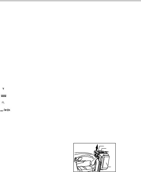
Installing or removing battery cartridge
1 |
1. |
Red part |
|
2. |
Button |
||
2 |
|||
|
3. |
Battery cartridge |
|
|
3 |
|
007482
•Always switch off the tool before insertion or removal of the battery cartridge.
•To remove the battery cartridge, withdraw it from the tool while sliding the button on the front of the cartridge.
4
•To insert the battery cartridge, align the tongue on the battery cartridge with the groove in the housing and slip it into place. Always insert it all the way until it locks in place with a little click. If you can see the red part on the upper side of the button, it is not locked completely. Insert it fully until the red part cannot be seen. If not, it may accidentally fall out of the tool, causing injury to you or someone around you.
•Do not use force when inserting the battery cartridge. If the cartridge does not slide in easily, it is not being inserted correctly.
Selecting the cutting action
1. Cutting action changing lever
1
007483
This tool can be operated with an orbital or a straight line (up and down) cutting action. The orbital cutting action thrusts the blade forward on the cutting stroke and greatly increases cutting speed.
To change the cutting action, just turn the cutting action changing lever to the desired cutting action position. Refer to the table to select the appropriate cutting action.
Position |
Cutting action |
Applications |
|
|
|
|
|
|
|
|
For cutting mild steel, |
0 |
|
Straight line |
stainless steel and plastics. |
|
cutting action |
For clean cuts in wood |
|
|
|
||
|
|
|
|
|
|
|
and plywood. |
|
|
Small orbit |
For cutting mild steel, |
|
|
cutting action |
aluminum and hard wood. |
|
|
||
|
|
|
|
|
|
|
For cutting wood and |
|
|
Medium orbit |
plywood. |
|
|
cutting action |
For fast cutting in |
|
|
||
|
|
|
aluminum and mild steel. |
|
|
|
|
|
|
Large orbit |
For fast cutting in |
|
|
cutting action |
wood and plywood. |
|
|
||
|
|
|
|
006376
Switch action
1 |
2 |
1. |
Lock-off button |
|
2. |
Switch trigger |
|
|
|
007484
1 |
1. Lock-off button |
|
|
B |
|
|
A |
007485
 CAUTION:
•Before inserting the battery cartridge into the tool, always check to see that the switch trigger actuates properly and returns to the "OFF" position when released.
•When not operating the tool, depress the lock-off
button from A side to lock the switch trigger in the OFF position.
To prevent the switch trigger from accidentally pulled, the lock-off button is provided.
To start the tool, depress the lock-off button from B side and pull the switch trigger.
Tool speed is increased by increasing pressure on the switch trigger. Release the switch trigger to stop. After use, always press in the lock-off button from A side.
Electric brake
This tool is equipped with an electric brake. If the tool consistently fails to quickly stop after switch trigger release, have tool serviced at a Makita service center.
Lighting up the lamps
 CAUTION:
•Do not look in the light or see the source of light
directly.
To turn on the lamp, pull the trigger. Release the trigger to turn it off.
NOTE:
•Use a dry cloth to wipe the dirt off the lens of lamp. Be careful not to scratch the lens of lamp, or it may lower the illumination.
5
ASSEMBLY
 CAUTION:
•Always be sure that the tool is switched off and the battery cartridge is removed before carrying out any work on the tool.
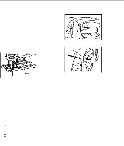
Installing or removing saw blade
 CAUTION:
•Always clean out all chips or foreign matter adhering to the blade and/or blade holder. Failure to do so may cause insufficient tightening of the blade, resulting in a serious personal injury.
•Do not touch the blade or the workpiece immediately after operation; they may be extremely hot and could burn your skin.
•Tighten the saw blade securely. Failure to do so may cause a serious injury.
•When you remove the saw blade, be careful not to hurt your fingers with the top of the blade or the tips of workpiece.
To install the blade, open the tool opener to the position shown in the figure.
1. Tool opener
1
001909
Keeping that situation, insert the saw blade into the blade clamp as far as the two protrusions of the blade can not be seen.
3 |
1. |
Blade clamp |
|
2. Jig saw blade |
|
|
3. |
Protrusions |
1 |
|
|
2 |
|
|
001910 |
|
|
Return the tool opener to its original position.
After installing, always make sure that the blade is securely held in place by trying to pull it out.
 CAUTION:
•Do not open the tool opener excessively, or it may
cause tool damage.
To remove the blade, open the tool opener to the position shown in the figure. Pull the saw blade out toward the base.
1. Jig saw blade
1
001911
NOTE:
• Occasionally lubricate the roller.
Hex wrench storage
1. Base
2. Hex wrench
1

 2
2
007486
When not in use, store the hex wrench as shown in the figure to keep it from being lost.
Cover plate
1 |
2 |
007503 |
1.Cover plate
2.Base
Use the cover plate when cutting decorative veneers, plastics, etc. It protects sensitive or delicate surfaces from damage. Fit it on the back of the tool base.
6
Anti-splintering device
1. Base
2. Anti-splintering
device

 1
1 
 2
2
007504
For splinter-free cuts, the anti-splintering device can be used. To install the anti-splintering device, move the tool base all the way forward and fit it from the back of tool base. When you use the cover plate, install the anti-splintering device onto the cover plate.
 CAUTION:
•The anti-splintering device cannot be used when making bevel cuts.
Dust extraction
The dust nozzle (optional accessory) is recommended to perform clean cutting operations.
1 |
1. |
Dust nozzle |
|
2. |
Base |
|
2 |
|
001921 |
|
|
To attach the dust nozzle on the tool, insert the hook of dust nozzle into the hole in the base.
The dust nozzle can be installed on either left or right side of the base.
1. Dust nozzle
2. Hose for vacuum cleaner

 2 1
2 1 

007495
OPERATION
 CAUTION:
•Always hold the base flush with the workpiece. Failure to do so may cause blade breakage, resulting in a serious injury.
1. Cutting line
2. Base
1
 2
2
007487
Turn the tool on without the blade making any contact and wait until the blade attains full speed. Then rest the base flat on the workpiece and gently move the tool forward along the previously marked cutting line.
NOTE:
•If the tool is operated continuously until the battery
cartridge has discharged, allow the tool to rest for 15 minutes before proceeding with a fresh battery.
When cutting curves, advance the tool very slowly.
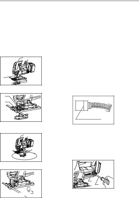
Bevel cutting
001922
Then connect a Makita vacuum cleaner to the dust nozzle.
007488
 CAUTION:
•Always be sure that the tool is switched off and the battery cartridge is removed before tilting the base.
With the base tilted, you can make bevel cuts at any angle between 0° and 45° (left or right).
7

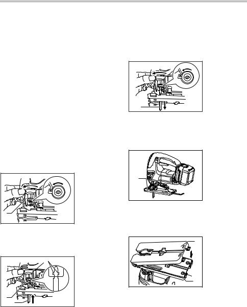
Loosen the bolt on the back of the base with the hex wrench. Move the base so that the bolt is positioned in the center of the bevel slot in the base.
1 |
2 |
3 |
1. |
Base |
|
|
2. |
Bolt |
|
|
|
|
||
|
|
|
3. |
Hex wrench |
007489 |
|
|
|
|
Tilt the base until the desired bevel angle is obtained. The V-notch of the gear housing indicates the bevel angle by graduations. Then tighten the bolt firmly to secure the base.
|
|
|
1. |
Bevel slot |
|
|
|
6 |
2. |
Base |
|
|
|
3. |
Bolt |
||
|
|
5 |
|||
|
|
4. |
Graduations |
||
|
|
|
|||
|
1 |
4 |
5. |
V-notch |
|
|
3 |
|
6. |
Gear housing |
|
|
|
|
|
||
|
2 |
|
|
|
|
007490 |
|
|
|
|
|
Front flush cuts |
|
|
|
||
1 |
2 |
3 |
1. |
Base |
|
2. |
Bolt |
||||
|
|
|
|||
|
|
|
3. |
Hex wrench |
|
007491 |
|
|
|
|
|
Loosen the bolt on the back of the base with the hex wrench and slide the base all the way back. Then tighten the bolt to secure the base.
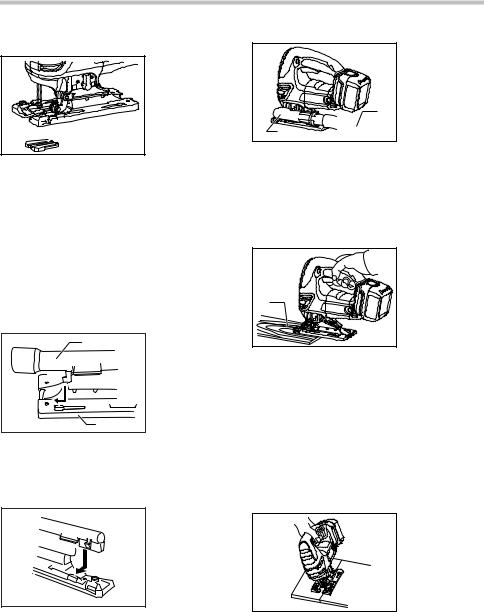
Cutouts
Cutouts can be made with either of two methods A or B.
A) Boring a starting hole:
1. Starting hole
 1
1
007492
•For internal cutouts without a lead-in cut from an
edge, pre-drill a starting hole 12 mm (1/2") or more in diameter. Insert the blade into this hole to start your cut.
B) Plunge cutting:
007493 |
•You need not bore a starting hole or make a lead-in
cut if you carefully do as follows.
1.Tilt the tool up on the front edge of the base with the blade point positioned just above the workpiece surface.
2.Apply pressure to the tool so that the front edge of the base will not move when you switch on the tool and gently lower the back end of the tool slowly.
3.As the blade pierces the workpiece, slowly lower the base of the tool down onto the workpiece surface.
4.Complete the cut in the normal manner.
Finishing edges
007494
To trim edges or make dimensional adjustments, run the blade lightly along the cut edges.
Metal cutting
Always use a suitable coolant (cutting oil) when cutting metal. Failure to do so will cause significant blade wear. The underside of the workpiece can be greased instead of using a coolant.
8
Rip fence set (optional accessory)
 CAUTION:
•Always be sure that the tool is switched off and the battery cartridge is removed before installing or removing accessories.
1.Straight cuts
When repeatedly cutting widths of 160 mm (6-5/16") or less, use of the rip fence will assure fast, clean, straight cuts. To install, insert the rip fence into the rectangular hole on the side of the tool base with the fence guide facing down. Slide the rip fence to the desired cutting width position, then tighten the bolt to secure it.
1. Rip fence
 1
1
007496
1
2
3
007497
2.Circular cuts
007498

 2 1
2 1


 3
3
007499
1.Hex wrench
2.Bolt
3.Fence guide
1.Fence guide
2.Threaded knob
3.Circular guide pin
When cutting circles or arcs of 170 mm (6-11/16") or less in radius, install the rip fence as follows.
•Insert the rip fence into the rectangular hole on the side of the base with the fence guide facing up. Insert the circular guide pin through either of the two holes on the fence guide. Screw the threaded knob onto the pin to secure the pin.
•Now slide the rip fence to the desired cutting radius, and tighten the bolt to secure it in place. Then move the base all the way forward.
NOTE:
•Always use blades No. B-17, B-18, B-26 or B-27 when cutting circles or arcs.
MAINTENANCE
 CAUTION:
•Always be sure that the tool is switched off and the battery cartridge is removed before attempting to perform inspection or maintenance.
Replacing carbon brushes
1. Limit mark
1
001145
Remove and check the carbon brushes regularly. Replace when they wear down to the limit mark. Keep the carbon brushes clean and free to slip in the holders. Both carbon brushes should be replaced at the same time. Use only identical carbon brushes.
Use a screwdriver to remove the brush holder caps. Take out the worn carbon brushes, insert the new ones and secure the brush holder caps.
1. Brush holder cap
2. Screwdriver
1  2
2
007505
9

After replacing brushes, insert the battery cartridge into the tool and break in brushes by running tool with no load for about 1 minute. Then check the tool while running and electric brake operation when releasing the switch trigger. If electric brake is not working well, ask your local Makita service center for repair.
To maintain product SAFETY and RELIABILITY, repairs, any other maintenance or adjustment should be performed by Makita Authorized or Factory Service Centers, always using Makita replacement parts.
ACCESSORIES
 CAUTION:
•These accessories or attachments are recommended for use with your Makita tool specified in this manual. The use of any other
accessories or attachments might present a risk of injury to persons. Only use accessory or attachment for its stated purpose.
If you need any assistance for more details regarding these accessories, ask your local Makita Service Center.
•Jig saw blades
•Hex wrench 4
•Rip fence (guide rule) set
•Anti-splintering device
•Cover plate
•Dust nozzle
•Various type of Makita genuine batteries and chargers
MAKITA LIMITED ONE YEAR WARRANTY
Warranty Policy
Every Makita tool is thoroughly inspected and tested before leaving the factory. It is warranted to be free of defects from workmanship and materials for the period of ONE YEAR from the date of original purchase. Should any trouble develop during this one year period, return the COMPLETE tool, freight prepaid, to one of Makita’s Factory or Authorized Service Centers. If inspection shows the trouble is caused by defective workmanship or material, Makita will repair (or at our option, replace) without charge.
This Warranty does not apply where:
repairs have been made or attempted by others:
repairs are required because of normal wear and tear:
the tool has been abused, misused or improperly maintained:
alterations have been made to the tool.
IN NO EVENT SHALL MAKITA BE LIABLE FOR ANY INDIRECT, INCIDENTAL OR CONSEQUENTIAL DAMAGES FROM THE SALE OR USE OF THE PRODUCT. THIS DISCLAIMER APPLIES BOTH DURING AND AFTER THE TERM OF THIS WARRANTY.
MAKITA DISCLAIMS LIABILITY FOR ANY IMPLIED WARRANTIES, INCLUDING IMPLIED WARRANTIES OF "MERCHANTABILITY" AND "FITNESS FOR A SPECIFIC PURPOSE," AFTER THE ONE YEAR TERM OF THIS WARRANTY.
This Warranty gives you specific legal rights, and you may also have other rights which vary from state to state. Some states do not allow the exclusion or limitation of incidental or consequential damages, so the above limitation or exclusion may not apply to you. Some states do not allow limitation on how long an implied warranty lasts, so the above limitation may not apply to you.
EN0006-1
10
 Loading...