


Makita 9067, 9067F, 9067SF, 9069, 9069F Manual
...
|
|
|
|
|
|
|
|
|
|
|
|
|
|
|
|
|
GB |
Angle Grinder |
Instruction Manual |
||||
|
|
|
|
|
|
|
|
|
|
Meuleuse d’angle |
Manuel d’instructions |
||||
|
F |
||||||
|
|
|
|
|
|
|
|
|
|
Winkelschleifer |
Betriebsanleitung |
||||
|
D |
||||||
|
|
|
|
|
|
|
|
|
|
Smerigliatrice angolare |
Istruzioni per l’uso |
||||
|
I |
||||||
|
|
|
|
|
|
|
|
|
|
Haakse slijpmachine |
Gebruiksaanwijzing |
||||
|
NL |
||||||
|
|
|
|
|
|
|
|
|
|
Amoladora |
Manual de instrucciones |
||||
|
E |
||||||
|
|
|
|
|
|
|
|
|
|
Rebarbadora |
Manual de instruções |
||||
|
P |
||||||
|
|
|
|
|
|
|
|
|
|
Vinkelsliber |
Brugsanvisning |
||||
|
DK |
||||||
|
|
|
|
|
|
|
|
|
|
Vinkelslipmaskin |
Bruksanvisning |
||||
|
S |
||||||
|
|
|
|
|
|
|
|
|
|
Vinkelsliper |
Bruksanvisning |
||||
|
N |
||||||
|
|
|
|
|
|
|
|
|
|
Kulmahiomakone |
Käyttöohje |
||||
|
SF |
||||||
|
|
|
|
|
|
|
|
|
|
Γωνιακ ς Λειαντήρας |
δηγίες ρήσεως |
||||
|
GR |
||||||
|
|
|
|
|
|
|
|
|
|
|
|
|
|
||
|
180 mm |
9067/9067S/9067L/9067H 9067F/9067SF |
|||||
|
230 mm |
9069/9069S/9069H |
9069F/9069SF |
||||
|
|
|
|
|
|
|
|
|
|
|
|
|
|
|
|
|
|
|
|
|
|
|
|

1
3 |
2 |
1
6
5
3 |
|
|
10 |
|
11 |
|
5 |
5 |
|
A |
B |
|
15˚ – 30˚ |
7
4 |
2 |
7 |
8 |
9 |
4 |
12 |
13 |
6 |
15 |
16 |
14 |
8 |
2
17
18
9
Symbols
The following show the symbols used for the tool. Be sure that you understand their meaning before use.
Symboles
Nous donnons ci-dessous les symboles utilisés pour l’outil. Assurez-vous que vous en avez bien compris la signification avant d’utiliser l’outil.
Symbole
Die folgenden Symbole werden für die Maschine verwendet. Machen Sie sich vor der Benutzung unbedingt mit ihrer Bedeutung vertraut.
Simboli
Per questo utensile vengono usati i simboli seguenti. Bisogna capire il loro significato prima di usare l’utensile.
Symbolen
Voor dit gereedschap worden de volgende symbolen gebruikt. Zorg ervoor dat u de betekenis van deze symbolen begrijpt alvorens het gereedschap te gebruiken.
Símbolos
A continuación se muestran los símbolos utilizados con esta herramienta. Asegúrese de que entiende su significado antes de usarla.
Símbolos
O seguinte mostra os símbolos utilizados para a ferramenta. Certifique-se de que compreende o seu significado antes da utilização.
Symboler
Nedenstående symboler er anvendt i forbindelse med denne maskine. Vær sikker på, at De har forstået symbolernes betydning, før maskinen anvendes.
Symboler
Det följande visar de symboler som används för den här maskinen. Se noga till att du förstår deras innebörd innan maskinen används.
Symbolene
Følgende viser de symblene som brukes for maskinen. Det er viktig å forstå betydningen av disse før maskinen tas i bruk.
Symbolit
Alla on esitetty koneessa käytetyt symbolit. Opettele näiden merkitys, ennen kuin käytät konetta.
Σύµ λα
Τα ακ λ υθα δεί ν υν τα σύµ λα π υ ρησιµ π ι ύνται για τ µη άνηµα. Βε αιωθείτε τι καταλα αίνετε τη σηµασία τ υς πριν απ τη ρήση.
3

Read instruction manual.
Lire le mode d’emploi.
Bitte Betriebsanleitung lesen.
Leggete il manuale di istruzioni.
Lees de gebruiksaanwijzing.
Lea el manual de instrucciones.
DOUBLE INSULATION
DOUBLE ISOLATION
DOPPELT SCHUTZISOLIERT
DOPPIO ISOLAMENTO
DUBBELE ISOLATIE
DOBLE AISLAMIENTO
Wear safety glasses.
Porter des lunettes de protection.
Schutzbrille tragen.
Indossare occhiali di protezione.
Draag een veiligheidsbril.
Póngase gafas de seguridad.
Leia o manual de instruções.
Læs brugsanvisningen.
Läs bruksanvisningen.
Les bruksanvisingen.
Katso käyttöohjeita.
∆ια άστε τις δηγίες ρήσης.
DUPLO ISOLAMENTO
DOBBELT ISOLERET
DUBBEL ISOLERING
DOBBEL ISOLERING
KAKSINKERTAINEN ERISTYS
∆ΙΠΛΗ Μ%ΝΩΣΗ
Utilize óculos de segurança.
Bær sikkerhedsbriller.
Bär skyddsglasögon.
Bruk vernebriller.
Käytä suojalaseja.
Φ ρέστε γυαλιά ασφαλείας.
4

ENGLISH
Explanation of general view
1 |
Wheel guard |
7 |
Lock nut |
13 |
Lock lever |
2 |
Screw |
8 |
Depressed center wheel |
14 |
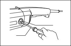
Carbon brush |
3 |
Notch |
9 |
Inner flange |
15 |
Insulating tip |
4 |
Side grip |
10 |
Lock nut wrench |
16 |
Commutator |
5 |
Shaft lock |
11 |
Tighten |
17 |
Brush holder cap |
6 |
Press |
12 |
Switch trigger |
18 |
Screwdriver |
|
|
|
|
|
|
SPECIFICATIONS
Model |
9067/9067S |
9067L |
9069/9069S |
|
9067F/9067SF/9067H |
|
9069F/9069SF/9069H |
Depressed center wheel diameter .......... |
180 mm |
180 mm |
230 mm |
Spindle thread ........................................ |
M14 |
M14 |
M14 |
No load speed (min-1) ............................. |
8,500 |
6,600 |
6,600 |
Overall length ......................................... |
458 mm |
458 mm |
458 mm |
Net weight ............................................... |
4.2 kg |
4.2 kg |
4.2 kg |
|
|
|
|
•Due to our continuing program of research and development, the specifications herein are subject to change without notice.
•Note: Specifications may differ from country to country.
Intended use
The tool is intended for cutting, grinding and sanding of metal and stone materials without the use of water.
Power supply
The tool should be connected only to a power supply of the same voltage as indicated on the nameplate, and can only be operated on single-phase AC supply. They are double-insulated in accordance with European Standard and can, therefore, also be used from sockets without earth wire.
For public low-voltage distribution systems of between 220 V and 250 V
Switching operations of electric apparatus cause voltage fluctuations. The operation of this device under unfavorable mains conditions can have adverse effects to the operation of other equipment. With a mains impedance equal or less than 0.31 Ohms it can be presumed that there will be no negative effects.
The mains socket used for this device must be protected with a fuse or protective circuit breaker having slow tripping characteristics.
Safety hints
For your own safety, please refer to the enclosed safety instructions.
ADDITIONAL SAFETY RULES
ENB031-3
1.Always wear safety goggles and ear protectors during operation.
2.Always be sure that the tool is switched off and unplugged before carrying out any work on the tool.
3.Keep guards in place.
4.Use only wheels with correct size and wheels having a maximum operating speed at least as high as the highest No Load Speed marked on the tool’s nameplate.When using depressed center wheels, be sure to use only fiberglass-rein- forced wheels.
5.Check the wheel carefully for cracks or damage before operation. Replace cracked or damaged wheel immediately.
6.Observe the instructions of the manufacturer for correct mounting and use of wheels. Handle and store wheels with care.
7.Do not use separate reducing bushings or adaptors to adapt large hole abrasive wheels.
8.Use only flanges specified for this tool.
9.Do not damage the spindle, the flange (especially the installing surface) or the lock nut. Damage to these parts could result in wheel breakage.
10.For tools intended to be fitted with threaded hole wheel, ensure that the thread in the wheel is long enough to accept the spindle length.
11.Before using the tool on an actual workpiece, test run the tool at the highest no load speed for at least 30 seconds in a safe position. Stop immediately if there is any vibration or wobbling that could indicate poor installation or a poorly balanced wheel. Check the tool to determine the cause.
12.Check that the workpiece is properly supported.
13.Hold the tool firmly.
14.Keep hands away from rotating parts.
15.Make sure the wheel is not contacting the workpiece before the switch is turned on.
16.Use the specified surface of the wheel to perform the grinding.
17.Do not use cutting off wheel for side grinding.
18.Watch out for flying sparks. Hold the tool so that sparks fly away from you and other persons or flammable materials.
19.Pay attention that the wheel continues to rotate after the tool is switched off.
20.Do not touch the workpiece immediately after operation; it may be extremely hot and could burn your skin.
21.Position the tool so that the power cord always stays behind the tool during operation.
22.If working place is extremely hot and humid, or badly polluted by conductive dust, use a shortcircuit breaker (30 mA) to assure operator safety.
5
 Loading...