


Leica M500 OH3
User manual
10 711 894 – Version -

Leica M500 OH3 / Ref. 10 711 894 / Version -

|
Survey of chapters |
Introduction |
3 |
Operating elements |
9 |
Preparation before surgery |
12 |
After surgery |
13 |
Operation |
14 |
Accessories |
31 |
Safety precautions |
34 |
Care and maintenance |
38 |
What to do if... |
40 |
Technical data |
43 |
Leica M500 OH3 / Ref. 10 711 894 / Version - |
1 |

Contents
|
Page |
|
Page |
Introduction |
|
Safety precautions |
|
User manual |
3 |
Intended use of instrument |
34 |
Product identification |
3 |
Directions for the person responsible for the |
|
Symbols used in this manual |
3 |
instrument |
34 |
Overview |
4 |
Directions for the user |
34 |
Function |
6 |
Dangers of use |
35 |
Operating elements |
|
Labelling |
36 |
Leica M500 N microscope with |
|
Care and maintenance |
|
microscope carrier |
9 |
Care instructions |
38 |
Control unit |
10 |
Replacing lamps |
38 |
Footswitches |
11 |
Replacing fuses |
39 |
Mouth switch |
11 |
Operational check |
39 |
Preparation before surgery |
|
What to do if...? |
|
Transportation |
12 |
General faults |
40 |
Preparations before surgery |
12 |
TV, photography |
42 |
Performing function checks |
13 |
Error messages at control unit |
42 |
Positioning at operating table |
13 |
Technical data |
|
After surgery |
|
Electrical data |
43 |
Tasks to be completed after surgery |
13 |
Leica M500 N |
43 |
Operation |
|
Accessories |
43 |
Setting/releasing footbrakes |
14 |
Floor stand |
44 |
Locking the Leica M500 OH3 |
14 |
Standards |
44 |
Selecting XYZ-Free/Focus-Lock brakes |
15 |
Environmental conditions |
44 |
Balancing out the Leica M500 OH3 |
15 |
Limitations on use |
44 |
Switching on illumination |
18 |
Dimensional drawings |
45 |
Switching from main illuminator to backup |
|
|
|
illuminator |
18 |
|
|
Setting light field diameter of illumination field and |
|
|
|
working distance |
19 |
|
|
Lock/release multifocal focus |
19 |
|
|
Selecting name of operating doctor at control unit |
20 |
|
|
Determining dioptres for users |
21 |
|
|
Setting up eyepieces |
21 |
|
|
Attaching protective glass to eyepiece |
21 |
|
|
Attaching sterile operating elements |
22 |
|
|
Operation of control unit |
22 |
|
|
Settings at control unit |
23 |
|
|
Controlling zoom and focus |
28 |
|
|
Pulling in additional cables |
29 |
|
|
Changing wheel counterweight at D axis |
30 |
|
|
Accessories |
|
|
|
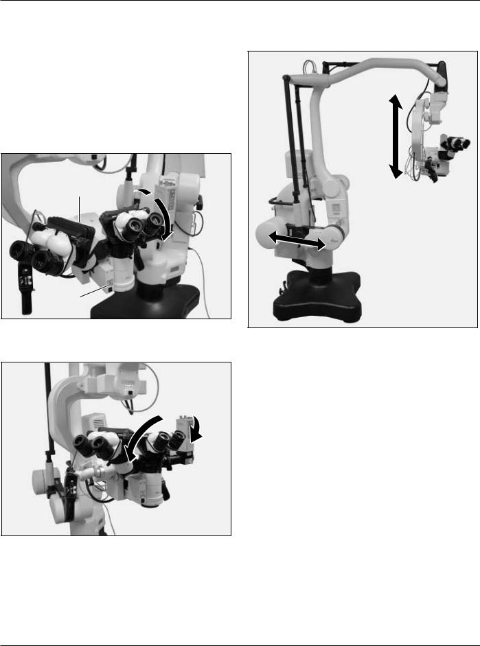
180° dual stereo attachment |
31 |
|
|
Binocular tube; can be tilted; with variable |
|
|
|
viewing angles 30°–150° |
31 |
|
|
Stereo/second-observer attachment |
31 |
|
|
Beam splitter with counterweight |
31 |
|
|
Video-zoom tube |
32 |
|
|
Adapter piece for accessories of the |
|
|
|
M 600 series |
32 |
|
|
Beam splitter |
32 |
|
|
Dual Imaging Color Module DI C500 |
32 |
|
|
Ultra Observer ULT500 |
32 |
|
|
Mounting accessories |
33 |
|
|
2 |
Leica M500 OH3 / Ref. 10 711 894 / Version - |

Introduction
User manual |
Symbols used in this manual |
This user manual contains important safety precautions as well as information on setting up the instrument (see the chapter entitled «Safety precautions»).
Before attempting to set up the product carefully read through the user manual.
Product identification
The model and serial number of your product are located on the identification label on the illumination unit. Copy this information into your user manual and always refer to it if you have questions for our representatives or service locations.
Model: |
Serial No.: |
The symbols used in this user manual have the following meaning:
Warning |
This indicates a potentially hazardous |
|
situation which could result in death or |
|
serious injury. |
Caution |
Indicates a potentially hazardous situation |
|
which, if not avoided, may result in minor |
|
or moderate injury and/or appreciable |
|
material, financial and environmental |
|
damage. It may also be used to alert |
|
against unsafe practices. |
|
Important paragraphs, which must be |
|
adhered to in practice as they enable the |
|
product to be used in a technically- |
|
correct and efficient manner. |
|
Indicates that you have to do something. |
Leica M500 OH3 / Ref. 10 711 894 / Version - |
3 |
Introduction
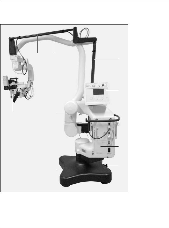
Overview
Leica M500 OH3 surgical microscope system
1 2
3
4
9 |
8 |
5
6
7
1 |
Horizontal cable channel |
6 |
Footbrake |
2 |
Swing arm |
7 |
Foot |
3 |
Vertical cable channel |
8 |
Locking knob |
4 |
Control unit |
9 |
Leica M500 N microscope |
5 |
Illumination unit |
|
|
4 |
Leica M500 OH3 / Ref. 10 711 894 / Version - |
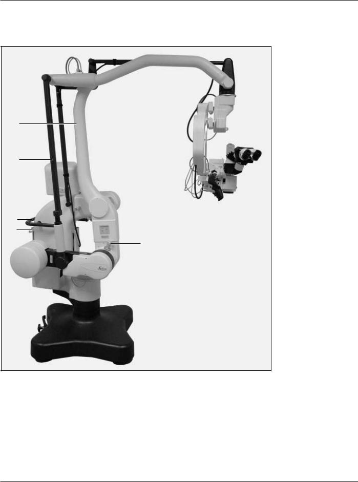
Introduction
1
2
3
4
5
1Vertical arm
2Tension rod
3Handle
4Footswitch holder
5Locking knob
Leica M500 OH3 / Ref. 10 711 894 / Version - |
5 |
Introduction
Function
Balancing system and brakes
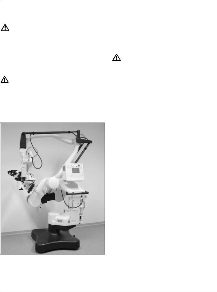
The Leica M500 OH3 surgical microscope consists of the Leica M500 N surgical microscope and the Leica OH3 floor stand.
The stand and surgical microscope are balanced out by the balancing system. All movements which must be carried out during the surgery require only minimal force.
The AB swivel movement is balanced out via the A and B pinion.
The internal weight of the stand balances the weight of the surgical microscope and the fitted accessories (movement D).
B  A B
A B
A
Movement C is balanced out at the microscope carrier.
C
6 |
Leica M500 OH3 / Ref. 10 711 894 / Version - |

Introduction
There are 6 electromagnetic brakes on the Leica M500 OH3 surgical microscope, which block movement of the base and surgical microscope:
•up/down and forward/backward in a parallelogram (0 and 1)
•at base (2)
•in microscope carrier (3)
•at A and B sledges of the surgical microscope (4)
•in rotatable joint (5)
5
3
4
1
0
2
Using the selector switch (Item 10, Page 10) for brakes (XYZ FREE or FOCUS LOCK) at the control unit, two different brake groupings can be selected.
The following movements with the surgical microscope can still be performed if the selector switch is located in the FOCUS LOCK position:
The following movements with the surgical microscope can be performed if the selector switch is located in the XYZ FREE position:
Leica M500 OH3 / Ref. 10 711 894 / Version - |
7 |
Introduction
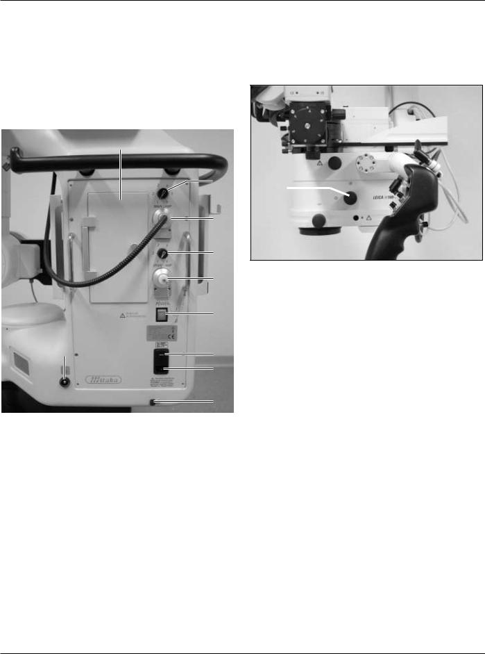
Illumination
The illumination of the Leica M500 OH3 surgical microscope consists of a main illuminator and a backup illuminator. They are located in the illumination unit.
The main and backup illuminators consist of xenon lamps. The light of the main and backup illuminators is lead to the optics carrier via a fibre-optic cable through the base.
If the main illuminator fails, the plug of the fibre-optic cable is switched over to the backup illumination.
|
1 |
|
2 |
|
3 |
|
4 |
|
5 |
|
6 |
10 |
7 |
|
|
|
8 |
|
9 |
|
|
1Access hatch for lamp inserts of main and backup illuminators
2Regulating knob for brightness of main illuminator
3Outlet for fibre-optic light guide of main illuminator
4Regulating knob for brightness of backup illuminator
5Outlet for fibre-optic light guide of backup illuminator
6Power switch of Leica M500 OH3 surgical microscope
7100 V/120 V/220 V/240 V switch
8Power connection
9Pullout fuse for power cable
10Potential equalisation connector
Two LEDs at the control unit indicate which illuminator is being used at the moment (see Page 18).
The light field diameter can be concentrated at the optics carrier with the rotary knob (11).
11
8 |
Leica M500 OH3 / Ref. 10 711 894 / Version - |
Operating elements
Leica M500 N microscope with microscope carrier
5
1
2 |
3 |
4 |
11 |
10 |
|
|
|
15 |
12 |
|
|
|
|
|
|
|
|
|
|
|
|
14 |
|
13 |
|
|
|
|
|
||
6 |
|
|
|
6 |
|
|
|
|
|
|
|||
|
|
|
|
|
||
|
|
9 |
8 |
7 |
|
|
10 |
|
|
||||
1Microscope carrier
2B sledge
3Switch for manual balancing of the B sledge
4Switch for manual balancing of the C sledge
5C sledge
6Handgrip
7Optics carrier
8 |
Switch for manual balancing of the A sledge |
Handgrips (Item 6): |
|
9 |
A sledge |
11 |
Joystick (selectable for XY movement or for menu control in |
10 |
Handgrip clamping lever |
|
DI C500) |
|
|
12 |
Focus |
|
|
13 |
Selector button (three brakes) |
|
|
14 |
ALL-FREE button (all brakes) |
|
|
15 |
Zoom |
Leica M500 OH3 / Ref. 10 711 894 / Version - |
9 |
Operating elements
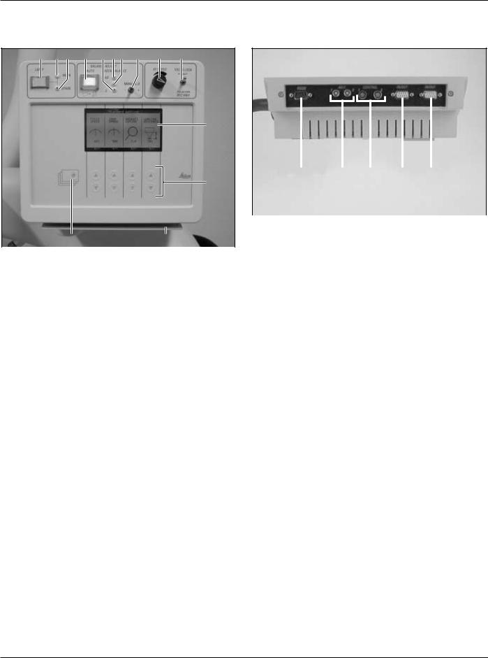
Control unit
1 |
2 |
3 |
4 |
5 |
6 |
7 |
8 |
9 |
10 |
|
|
|
|
11 |
|
|
|
|
|
|
|
|
|
|
|
|
|
|
|
|
|
|
|
|
|
|
|
|
|
|
|
|
|
|
|
|
|
|
|
|
|
|
|
|
|
|
|
|
|
|
|
|
|
|
|
|
|
|
|
|
|
|
|
|
|
|
12 |
|
|
15 |
|
16 |
17 |
18 |
19 |
||||||||
|
|
|
|
|
|
|
|
|
|
|
|
|
|
|
|
|
|
|
|
|
|
|
|
|
|
|
|
||||||||||||||
|
|
14 |
13 |
|
Connections on the underside of the control unit (cover for |
|||||||||||||||
|
|
|
connections, Item 13 removed): |
|
|
|
|
|
||||||||||||
|
|
|
|
|
15 |
RS-232 interface |
|
|
|
|
|
|
|
|
|
|
|
|||
1 |
Pushbutton for illumination (on/off) |
|
16 |
On/Off connection for external device |
|
|
||||||||||||||
2 |
LED for main illuminator |
|
17 |
Footswitches 1 and 2 |
|
|
|
|
|
|
|
|
|
|||||||
3 |
LED for backup illuminator |
|
18 |
CAN bus interface |
|
|
|
|
|
|
|
|
|
|
|
|||||
4 |
Pushbutton for auto balance with protective flap |
19 |
CAN bus interface |
|
|
|
|
|
|
|
|
|
|
|
||||||
5LED for balancing of D axis
6LED for balancing of A/B axis
7LED for balancing of C axis
8Toggle switch for manual balancing of D axis
9Regulating knob for movement speed of the X/Y axes
10Selector switch for brakes:
-XYZ-Free
-Focus-Lock
11Display
12Arrow keys
13Cover for connections
14Display key for menu control
10 |
Leica M500 OH3 / Ref. 10 711 894 / Version - |
Operating elements
Footswitch |
Mouth switch |
1 |
1 |
Y+ |
Y+ |
X- |
X+ |
7 |
X- |
X+ |
|
8 |
2 |
|
3 |
|
|
8 |
|
2 |
|
||
Y- |
Y- |
9 |
|||
7 |
3 |
|
|
||
|
|
|
|
||
6 |
4 |
6 |
|
4 |
|
|
5 |
|
5 |
|
|
1 Adjustable supports |
9 Brakes XYZ FREE |
2DI C500: Activate/deactivate imaging (On/Off)
3Focus, short working distance
4DI C500: Individual switching of shutters DI C500 with IGS workstation: ENTER menu
5Zoom (freely configurable; for default configuration, see Page 25)
6DI C500: Decrease the brightness of the displayed image DI C500 with IGS workstation: Menu scroll down
7Focus, long working distance
8DI C500: Increase the brightness of the displayed image DI C500 with IGS workstation: Menu scroll up
Leica M500 OH3 / Ref. 10 711 894 / Version - |
11 |
Preparation before surgery
Transportation Preparations before surgery
Warning
Risk of injury by:
•Uncontrolled swinging out of swing arm!
•Tilting of the stand!
•Feet in lightweight shoes can become trapped beneath the base!
When transporting the surgical microscope, always return it to the transport position.
Always push the surgical microscope, never pull it.
Caution
Microscope can be damaged by uncontrolled tilting over!
Hold the handgrips firmly before pressing the ALL-
FREE button.
Press the ALL-FREE button and bring the Leica M500 OH3 into the transport position (see figure below).
Cleaning optical accessories
Inspect the cleanliness of the eyepieces and objective as well as any photo or TV adapters as appropriate.
Remove dust and dirt.
Mounting accessories
Warning
Mortal danger from electrical shock!
Connect the Leica M500 OH3 surgical microscope to an earthed outlet only.
Lock the Leica M500 OH3 (see Page 14).Connect power cable.
Switch on power switch.Set footbrakes (see page 14).
Outfit microscope with all accessories for use.Position hand/mouth switch.
Position handgrips as needed for the forthcoming surgery.Screw off cover of connections (Item 13, Page 10), connect
provided footswitch and check settings (see Page 25).
Balancing out microscope
Balance out the Leica M500 OH3 (see Page 15).Release locks (see Page 14).
Setting up eyepieces
Set eye-base and pupil-base (see Page 19).Set dioptre values for users (see Page 21).
Configuring control unit
See the section entitled «Operation of the control unit», Page 22.
Check settings of the handgrips (DIC function or XY movement) (see Page 26).
Inspect all connections and make certain that all accessories are seated firmly.
Release footbrakes (see Page 14).Move Leica M500 OH3 via handgrip.
12 |
Leica M500 OH3 / Ref. 10 711 894 / Version - |
Preparation before surgery/After surgery
Performing function checks
Illumination
Always allow the main and backup illuminators to remain lit for at least five minutes, otherwise the lighting capacity will be quickly reduced.
Switch on main illuminator at the illumination unit (see Page 18).
Switch to backup illuminator at the illumination unit (see Page 18).
Switch illumination off again.
Footswitch
Test all functions with the footswitch.
Handgrip
Press the selection and ALL-FREE buttons and check movement.
Set the movement speed of the X/Y axes with the regulating knob (Item 9, Page 10) if necessary.
TV camera/monitor and still-photo camera
(if present)
Check the image on the TV monitor.
Align TV and SLR camera to the microscopic image.For photographs: Insert daylight film.
Sterility
Attach sterile components and sterile drapes (see Page 22).
Balancing out microscope
Balance out the Leica M500 OH3 (see Page 15).Press the ALL-FREE button and check balancing.
Positioning at operating table
Warning
Risk of injury from tilting surgical microscope!
Never change the accessories or attempt to rebalance the microscope while it is over the field of operation.
Lock the Leica M500 OH3 each time before changing accessories.
Balance out the Leica M500 OH3 each time after changing accessories.
Do not release brakes in an unbalanced state.
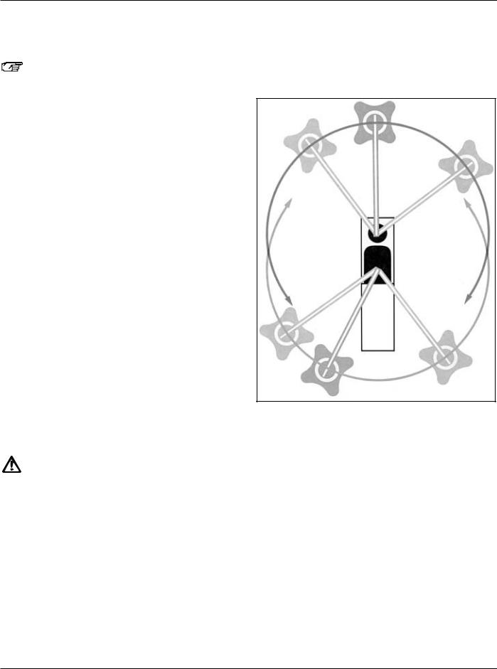
Positioning the Leica M500 OH3 at the operating table is quite easy and offers a multitude of options, whether it be for surgery at the head, spinal column, etc.
This freedom to choose your position with the M500 OH3 is thanks to the extra-long and high swing arm.
Release footbrakes (see Page 14).
Carefully move the Leica M500 OH3 surgical microscope to the operating table and position it for the forthcoming surgery.
Positioning possibilities:
Set footbrake.Position footswitch.
Connect potential equalisation.
Tasks to be completed after surgery
Swing microscope away.
Move Leica M500 OH3 to the transport position and out of the operating area.
Remove sterile components.Lock the Leica M500 OH3.
Move the Leica M500 OH3 to the parked position.
Leica M500 OH3 / Ref. 10 711 894 / Version - |
13 |
Operation
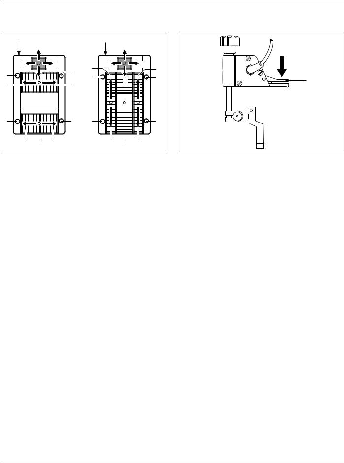
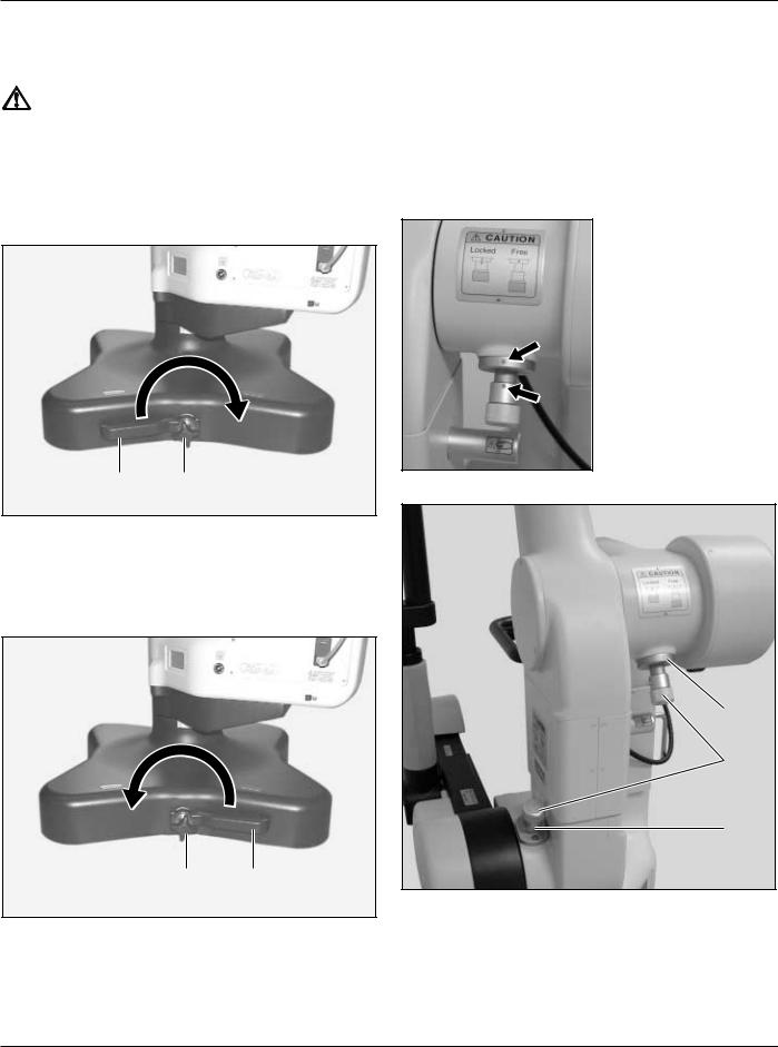
Setting/releasing footbrakes
Warning
Surgical microscope can move without warning!
Always set footbrakes, except during transport.
Setting footbrakes
Loosen star grip (2).
Turn lever for footbrake (1) to the right.Tighten star grip again.
Locking the Leica M500 OH3
The D axis of the Leica M500 OH3 is locked when locking is performed.
Locking is mainly used for installation and accessory-change at the Leica M500 OH3.
Pull out and turn locking knobs (4) until both points (arrows) are aligned.
1 2
Releasing footbrakes
Loosen star grip (2).
Turn lever for footbrake (1) to the left.Tighten star grip again.
3
4
5
2 1
14 |
Leica M500 OH3 / Ref. 10 711 894 / Version - |
 Loading...