


 Loading...
Kyocera ECOSYS M2135dn, ECOSYS M2635dn, ECOSYS M2635dw, ECOSYS M2735dw, ECOSYS M2040dn Service Manual
...ECOSYS M2135dn
ECOSYS M2635dn
ECOSYS M2635dw
ECOSYS M2735dw
ECOSYS M2040dn
ECOSYS M2540dn
ECOSYS M2540dw
ECOSYS M2640idw
PF-1100
SERVICE
MANUAL
Published in November 2016
842S0111
2S0SM061
Rev.1
CAUTION
RISK OF EXPLOSION IF BATTERY IS REPLACED BY AN INCORRECT TYPE. DISPOSE OF USED BATTERIES ACCORDING TO THE INSTRUCTIONS.
It may be illegal to dispose of this battery into the municipal waste stream. Check with your local solid waste officials for details in your area for proper disposal.
ATTENTION
IL Y A UN RISQUE D’EXPLOSION SI LA BATTERIE EST REMPLACEE PAR UN MODELE DE TYPE INCORRECT. METTRE AU REBUT LES BATTERIES UTILISEES SELON LES INSTRUCTIONS DONNEES.
Il peut être illégal de jeter les batteries dans des eaux d’égout municipales. Vérifiez avec les fonctionnaires municipaux de votre région pour les détails concernant des déchets solides et une mise au rebut appropriée.
Notation of products in the manual
For the purpose of this service manual, products are identified by print speed.
Product name |
|
|
Manual classification |
|
|
KDJ |
KDA |
KDE |
KDAU |
|||
|
|
|
|
|
|
|
|
|
|
|
|
|
ECOSYS M2135dn |
|
- |
|
LCD |
- |
|
|
|
× |
○ |
○ |
× |
|
|
|
|
|
|
|
|
|
|
|
||
ECOSYS M2635dn |
35 ppm |
|
|
|
ADF |
|
× |
× |
○ |
○ |
||
|
|
|
|
|
|
|||||||
|
|
|
|
|
|
|
|
|
|
|
||
ECOSYS M2635dw |
Wi-Fi |
|
|
FAX |
|
- |
× |
○ |
× |
× |
||
|
|
|
|
|
||||||||
|
|
|
|
|
|
|
|
|
|
|
||
ECOSYS M2735dw |
|
|
TSI |
|
|
|
× |
× |
○ |
○ |
||
|
|
|
|
|
|
|
||||||
|
|
|
|
|
|
|
|
|
|
|
|
|
ECOSYS M2040dn |
|
- |
|
LCD |
- |
|
|
|
× |
○ |
○ |
○ |
|
|
|
|
|
|
|
|
|
|
|
||
ECOSYS M2540dn |
40 ppm |
|
|
|
DADF |
|
× |
× |
○ |
○ |
||
|
|
|
|
|
|
|||||||
|
|
|
|
|
|
|
|
|
|
|
||
ECOSYS M2540dw |
Wi-Fi |
|
|
FAX |
|
|
○ |
○ |
× |
× |
||
|
|
|
|
|
|
|||||||
|
|
|
|
|
|
|
|
|
|
|
|
|
ECOSYS M2640idw |
|
|
TSI |
|
|
|
HyPAS |
○ |
○ |
○ |
○ |
|
|
|
|
|
|
|
|||||||
|
|
|
|
|
|
|
|
|
|
|
|
|
Revision history
Revision |
Date |
Pages |
Revised contents |
|
|
|
|
1 |
2 November 2016 |
CONTENTS |
Chenge: Page number |
|
|
|
|
|
|
1-4, 1-5 |
Added: FAX functions |
|
|
|
|
|
|
2-4 |
Added: Name of parts number 7 |
|
|
|
|
|
|
2-9 |
Correction: Description of "IMPORTANT" |
|
|
|
|
|
|
3-2 |
Correction: Item name of 3-2/3-2(1) |
|
|
|
Added: 4. Fuser pressure release motor |
|
|
|
|
|
|
3-11 |
Correction: Description of the thermopile |
|
|
|
|
|
|
4-3, 4-4 |
Correction: Maintenance kits |
|
|
6-9, 6-10 |
|
|
|
|
|
|
|
4-36 to 38 |
Correction: Correction: Procedure of detaching and |
|
|
|
rettaching the laser scanner unit |
|
|
|
|
|
|
4-75 |
Deleted: Procedure of detaching the front cover |
|
|
|
|
|
|
4-95 to 99 |
Added: Procedure of detaching the Wi-Fi PWB |
|
|
|
|
|
|
6-68 |
Deleted: Destination code (22) |
|
|
|
|
|
|
7-2 |
Correction: rear cover → cover |
|
|
|
Deleted: (1-1)Step2 to 4 |
|
|
|
|
|
|
7-9, 7-10 |
Added: J4002 to J4018 |
|
|
|
|
|
|
7-15 to 83 |
Added: 7-2 Self diagnostic, 7-3 Image formation failure |
|
|
|
7-4 Electric failure, 7-5 Mechanical failure |
|
|
|
|

This page is intentionally left blank.

Safety precautions
This booklet provides safety warnings and precautions for our service personnel to ensure the safety of their customers, their machines as well as themselves during maintenance activities. Service personnel are advised to read this booklet carefully to familiarize themselves with the warnings and precautions described here before engaging in maintenance activities.

Safety warnings and precautions
Various symbols are used to protect our service personnel and customers from physical danger and to prevent damage to their property. These symbols are described below:
 DANGER: High risk of serious bodily injury or death may result from insufficient attention to or incorrect compliance with warning messages using this symbol.
 WARNING: Serious bodily injury or death may result from insufficient attention to or incorrect compliance with warning messages using this symbol.
 CAUTION: Bodily injury or damage to property may result from insufficient attention to or incorrect compliance with warning messages using this symbol.
Symbols
The triangle ( ) symbol indicates a warning including danger and caution. The specific point of attention is shown inside the symbol.
General warning. |
Warning of risk of electric shock. |
Warning of high temperature.
 indicates a prohibited action. The specific prohibition is shown inside the symbol.
General prohibited action. |
Disassembly prohibited. |
 indicates that action is required. The specific action required is shown inside the symbol.
General action required. |
Remove the power plug from the wall outlet. |
Always ground the copier.

1. Installation Precautions
 WARNING
•Do not use a power supply with a voltage other than that specified. Avoid multiple connections to one outlet: they may cause fire or electric shock. When using an extension cable, always check that it is adequate for the rated current. .....................................................................................................
•Connect the ground wire to a suitable grounding point. Not grounding the copier may cause fire or electric shock. Connecting the earth wire to an object not approved for the purpose may cause explosion or electric shock. Never connect the ground cable to any of the following: gas pipes, lightning rods, ground cables for telephone lines and water pipes or faucets not approved by the proper authorities. ..........................................................................................................................................
 CAUTION:
•Do not place the copier on an infirm or angled surface: the copier may tip over, causing injury. .........
•Do not install the copier in a humid or dusty place. This may cause fire or electric shock. .................
•Do not install the copier near a radiator, heater, other heat source or near flammable material. This may cause fire. ...................................................................................................................................
•Allow sufficient space around the copier to allow the ventilation grills to keep the machine as cool as possible. Insufficient ventilation may cause heat buildup and poor copying performance. ............
•Always handle the machine by the correct locations when moving it. .................................................
•Always use anti-toppling and locking devices on copiers so equipped. Failure to do this may cause the copier to move unexpectedly or topple, leading to injury. ..............................................................
•Avoid inhaling toner or developer excessively. Protect the eyes. If toner or developer is accidentally ingested, drink a lot of water to dilute it in the stomach and obtain medical attention immediately. If it gets into the eyes, rinse immediately with copious amounts of water and obtain medical atten-
tion. .....................................................................................................................................................
•Advice customers that they must always follow the safety warnings and precautions in the copier’s instruction handbook. .........................................................................................................................

2. Precautions for Maintenance
 WARNING
•Always remove the power plug from the wall outlet before starting machine disassembly. ................
•Always follow the procedures for maintenance described in the service manual and other related brochures. ..........................................................................................................................................
•Under no circumstances attempt to bypass or disable safety features including safety mechanisms and protective circuits. ........................................................................................................................
•Always use parts having the correct specifications. ............................................................................
•Always use the thermostat or thermal fuse specified in the service manual or other related brochure when replacing them. Using a piece of wire, for example, could lead to fire or other serious accident. ...................................................................................................................................................
•When the service manual or other serious brochure specifies a distance or gap for installation of a part, always use the correct scale and measure carefully. ..................................................................
•Always check that the copier is correctly connected to an outlet with a ground connection. ...............
•Check that the power cable covering is free of damage. Check that the power plug is dust-free. If it is dirty, clean it to remove the risk of fire or electric shock. .................................................................
•Never attempt to disassemble the optical unit in machines using lasers. Leaking laser light may damage eyesight. ...............................................................................................................................
•Handle the charger sections with care. They are charged to high potentials and may cause electric shock if handled improperly. ...............................................................................................................
 CAUTION
•Wear safe clothing. If wearing loose clothing or accessories such as ties, make sure they are safely secured so they will not be caught in rotating sections. ......................................................................
•Use utmost caution when working on a powered machine. Keep away from chains and belts. ..........
•Handle the fixing section with care to avoid burns as it can be extremely hot. ..................................
•Check that the fixing unit thermistor, heat and press rollers are clean. Dirt on them can cause abnormally high temperatures. ...........................................................................................................

•Do not remove the ozone filter, if any, from the copier except for routine replacement. ......................
•Do not pull on the AC power cord or connector wires on high-voltage components when removing them; always hold the plug itself. ........................................................................................................
•Do not route the power cable where it may be stood on or trapped. If necessary, protect it with a cable cover or other appropriate item. ................................................................................................
•Treat the ends of the wire carefully when installing a new charger wire to avoid electric leaks. ..........
•Remove toner completely from electronic components. .....................................................................
•Run wire harnesses carefully so that wires will not be trapped or damaged. ......................................
•After maintenance, always check that all the parts, screws, connectors and wires that were removed, have been refitted correctly. Special attention should be paid to any forgotten connector, trapped wire and missing screws. .......................................................................................................
•Check that all the caution labels that should be present on the machine according to the instruction handbook are clean and not peeling. Replace with new ones if necessary. .......................................
•Handle greases and solvents with care by following the instructions below: ......................................
·Use only a small amount of solvent at a time, being careful not to spill. Wipe spills off completely.
·Ventilate the room well while using grease or solvents.
·Allow applied solvents to evaporate completely before refitting the covers or turning the power switch on.
·Always wash hands afterwards.
•Never dispose of toner or toner bottles in fire. Toner may cause sparks when exposed directly to fire in a furnace, etc. ...........................................................................................................................
•Should smoke be seen coming from the copier, remove the power plug from the wall outlet immediately. ...................................................................................................................................................
3. Miscellaneous
 WARNING
•Never attempt to heat the drum or expose it to any organic solvents such as alcohol, other than the specified refiner; it may generate toxic gas. ........................................................................................
•Keep the machine away from flammable liquids, gases, and aerosols. A fire or an electric shock might occur. ........................................................................................................................................

This page is intentionally left blank.
|
|
2S0/2S1/2S2/2S3/2S4/2S5/2SG/2SH/3RA-1 |
|
|
|
CONTENTS |
|
1 |
Specifications |
|
|
|
1-1 Specifications ........................................................................................................................... |
1-1 |
|
|
(1) |
Common function ................................................................................................................ |
1-1 |
|
(2) |
Copy Functions.................................................................................................................... |
1-3 |
|
(3) |
Printer Functions ................................................................................................................. |
1-3 |
|
(4) |
Scanner Functions............................................................................................................... |
1-4 |
|
(5) |
FAX Functions ..................................................................................................................... |
1-4 |
|
(6) |
Document Processor ........................................................................................................... |
1-5 |
|
(7) |
Paper Feeder (PF-1100)(Option) ........................................................................................ |
1-6 |
|
1-2 Part Names............................................................................................................................... |
1-7 |
|
|
(1) |
Machine Exterior.................................................................................................................. |
1-7 |
|
(2) |
Connectors/Interior .............................................................................................................. |
1-8 |
|
(3) |
With Optional Equipments Attached.................................................................................... |
1-9 |
|
(4) |
Operation Panel (TSI)........................................................................................................ |
1-10 |
|
(5) |
Operation Panel Keys (LCD) ............................................................................................. |
1-11 |
|
1-3 Overview of Optional Equipment ............................................................................................ |
1-13 |
|
|
(1) |
Expansion Memory............................................................................................................ |
1-14 |
|
(2) |
PF-1100 "Paper Feeder" ................................................................................................... |
1-15 |
|
(3) |
Card Authentication Kit(B) "Card Authentication Kit"......................................................... |
1-15 |
|
(4) |
UG-33 "ThinPrint Option" .................................................................................................. |
1-15 |
|
(5) |
SD/SDHC Memory Card.................................................................................................... |
1-15 |
2 |
Installation |
|
|
|
2-1 Environment ............................................................................................................................. |
2-1 |
|
|
2-2 Installing the main unit.............................................................................................................. |
2-2 |
|
|
(1) |
Unpacking and checking bundled items .............................................................................. |
2-3 |
|
|
(1-1) Main unit..................................................................................................................... |
2-3 |
|
|
(1-2) Paper Feeder (Option) ............................................................................................... |
2-4 |
|
(2) |
Installing the optional equipment ......................................................................................... |
2-5 |
|
(3) |
Connecting to other device.................................................................................................. |
2-5 |
|
(4) |
Connecting to the cable....................................................................................................... |
2-6 |
|
|
(4-1) LAN Cable .................................................................................................................. |
2-6 |
|
|
(4-2) USB cable .................................................................................................................. |
2-6 |
|
(5) |
Loading Paper ..................................................................................................................... |
2-7 |
|
(6) |
Power-up ............................................................................................................................. |
2-9 |
|
(7) |
Default (TSI model) ........................................................................................................... |
2-10 |
|
|
(7-1) Setting Date and Time.............................................................................................. |
2-10 |
|
|
(7-2) Network Settings ...................................................................................................... |
2-11 |
|
|
(7-3) Altitude Adjustment Setting ...................................................................................... |
2-12 |
|
(7) |
Default (LCD model).......................................................................................................... |
2-13 |
|
|
(7-1) Setting Date and Time.............................................................................................. |
2-13 |
|
|
(7-2) Network Settings ...................................................................................................... |
2-14 |
|
|
(7-3) Altitude Adjustment Setting ...................................................................................... |
2-16 |
|
(8) |
Installing Software ............................................................................................................. |
2-17 |
|
(9) |
Output Maintenance Report (Executing Maintenance mode U000) (For Service) ............ |
2-18 |
|
(10) |
Clearing the counts (Executing Maintenance Mode U927) (For service) .......................... |
2-18 |
|
(11) |
Terminating the maintenance mode (For service)............................................................. |
2-18 |
|
(12) |
Installing the main unit is complete.................................................................................... |
2-18 |
2S0/2S1/2S2/2S3/2S4/2S5/2SG/2SH/3RA-1
3 Machine Design |
|
|
3-1 Cross-section view ................................................................................................................... |
3-1 |
|
(1) |
Main unit + Document processor + Paper feeder (option)................................................... |
3-1 |
3-2 The configuration of the electrical components ........................................................................ |
3-2 |
|
(1) |
Electric parts........................................................................................................................ |
3-2 |
|
(1-1) Machine left side ........................................................................................................ |
3-2 |
|
(1-2) Machine right side ...................................................................................................... |
3-3 |
|
(1-3) Document processor .................................................................................................. |
3-4 |
|
(1-4) Paper feeder (option) ................................................................................................. |
3-4 |
(2) |
Descriptions about the major PWBs.................................................................................... |
3-5 |
|
(2-1) Main/Engine PWB ...................................................................................................... |
3-5 |
|
(2-2) High-voltage PWB ...................................................................................................... |
3-5 |
|
(2-3) Power source PWB .................................................................................................... |
3-5 |
|
(2-4) Operation panel PWB (TSI)........................................................................................ |
3-6 |
|
(2-5) Operation panel PWB (LCD) ...................................................................................... |
3-6 |
(3) |
Electric parts layout ............................................................................................................. |
3-7 |
|
(3-1) PWBs ......................................................................................................................... |
3-7 |
|
(3-2) Sensors and Switches.............................................................................................. |
3-10 |
|
(3-3) Motors ...................................................................................................................... |
3-13 |
|
(3-4) Others....................................................................................................................... |
3-15 |
3-3 Drive system........................................................................................................................... |
3-17 |
|
(1) |
Drive system for the paper conveying ............................................................................... |
3-17 |
(2) |
Each section drive ............................................................................................................. |
3-18 |
|
(2-1) Primary paper feed drive .......................................................................................... |
3-18 |
|
(2-2) Drum drive................................................................................................................ |
3-18 |
|
(2-3) Developer drive ........................................................................................................ |
3-19 |
|
(2-4) Fuser unit drive......................................................................................................... |
3-19 |
3-4 Mechanical construction ......................................................................................................... |
3-20 |
|
(1) |
Paper feed section............................................................................................................. |
3-20 |
|
(1-1) Cassette paper feed section..................................................................................... |
3-20 |
|
(1-2) MP tray paper feed section ...................................................................................... |
3-22 |
(2) |
Optical section ................................................................................................................... |
3-24 |
|
(2-1) Image scanner unit................................................................................................... |
3-24 |
|
(2-2) Laser scanner unit.................................................................................................... |
3-26 |
(3) |
Developer section.............................................................................................................. |
3-28 |
|
(3-1) Developer unit .......................................................................................................... |
3-28 |
(4) |
Drum section ..................................................................................................................... |
3-30 |
|
(4-1) Main charger unit...................................................................................................... |
3-30 |
|
(4-2) Cleaning ................................................................................................................... |
3-30 |
(5) |
Conveying/Transfer and Separation section ..................................................................... |
3-32 |
(6) |
Fuser section ..................................................................................................................... |
3-34 |
(7) |
Eject and feedshift section................................................................................................. |
3-36 |
(8) |
Duplex conveying section.................................................................................................. |
3-38 |
(9) |
Document processor ......................................................................................................... |
3-40 |
(10) |
Paper feeder (option)......................................................................................................... |
3-42 |
4 Maintenance
4-1 Precautions for the maintenance.............................................................................................. |
4-1 |
|
(1) |
Precautions.......................................................................................................................... |
4-1 |
(2) |
Storage and handling of the drum ....................................................................................... |
4-1 |
(3) |
Storage of the toner container ............................................................................................. |
4-1 |
|
2S0/2S1/2S2/2S3/2S4/2S5/2SG/2SH/3RA-1 |
|
(4) |
Screening of the toner container ......................................................................................... |
4-2 |
4-2 Maintenance parts .................................................................................................................... |
4-3 |
|
(1) |
Maintenance kits.................................................................................................................. |
4-3 |
(2) |
Executing the maintenance mode after replacing the maintenance kit ............................ |
4-3 |
(3) |
Maintenance parts list.......................................................................................................... |
4-3 |
(4) |
Periodic maintenance Procedures....................................................................................... |
4-4 |
4-3 Maintenance parts replacement procedures ............................................................................ |
4-5 |
|
(1) |
Cassette paper feed section................................................................................................ |
4-5 |
|
(1-1) Detaching and reattaching the Paper feed roller........................................................ |
4-5 |
|
(1-2) Detaching and reattaching the retard roller ................................................................ |
4-6 |
|
(1-3) Detaching and reattaching the MP paper feed pulley ................................................ |
4-8 |
(2) |
Developer section.............................................................................................................. |
4-10 |
|
(2-1) Detaching and reattaching the developer unit.......................................................... |
4-10 |
(3) |
Drum section ..................................................................................................................... |
4-11 |
|
(3-1) Detaching and reattaching the drum unit ................................................................. |
4-11 |
|
(3-2) Detaching and reattaching the main charger unit..................................................... |
4-13 |
(4) |
Transfer section................................................................................................................. |
4-14 |
|
(4-1) Detaching and reattaching the transfer roller unit .................................................... |
4-14 |
(5) |
Fuser section ..................................................................................................................... |
4-17 |
|
(5-1) Detaching and reattaching the fuser unit.................................................................. |
4-17 |
4-4 Disassembly and Reassembly ............................................................................................... |
4-21 |
|
(1) |
Outer covers ...................................................................................................................... |
4-21 |
|
(1-1) Detaching and reattaching the left rear cover .......................................................... |
4-21 |
|
(1-2) Detaching and reattaching the ISU rear cover ......................................................... |
4-21 |
|
(1-3) Detaching and reattaching the ISU left cover........................................................... |
4-22 |
|
(1-4) Detaching and reattaching the ISU right cover......................................................... |
4-22 |
|
(1-5) Detaching and reattaching the left cover.................................................................. |
4-23 |
|
(1-6) Detaching and reattaching the right cover................................................................ |
4-24 |
|
(1-7) Detaching and reattaching the front cover ............................................................... |
4-26 |
|
(1-8) Detaching and reattaching the rear cover ................................................................ |
4-27 |
(2) |
Optical section ................................................................................................................... |
4-28 |
|
(2-1) Detaching and reattaching the laser scanner unit (LSU).......................................... |
4-28 |
|
(2-2) Detaching and reattaching the image scanner unit (ISU)......................................... |
4-39 |
|
(2-3) Detaching and reattaching the operation panel (TSI model).................................... |
4-45 |
|
(2-4) Detaching and reattaching the operation panel (LCD model) .................................. |
4-47 |
|
(2-5) Detaching and reattaching the ISU top frame .......................................................... |
4-48 |
|
(2-6) Detaching and reattaching the scanner carriage assembly ..................................... |
4-48 |
(3) |
Drive section...................................................................................................................... |
4-49 |
|
(3-1) Detaching and reattaching the main motor .............................................................. |
4-49 |
|
(3-2) Detaching and reattaching the fuser pressure release drive unit ............................. |
4-54 |
|
(3-3) Detaching and reattaching the MP solenoid (front side) .......................................... |
4-60 |
|
(3-4) Detaching reattaching the clutch. ............................................................................. |
4-64 |
|
(3-5) Detaching and reattaching the eject solenoid .......................................................... |
4-70 |
(4) |
Others................................................................................................................................ |
4-83 |
|
(4-1) Detaching and reattaching the speaker.................................................................... |
4-83 |
|
(4-2) Detaching and reattaching the eraser ...................................................................... |
4-89 |
|
(4-3) Replacing the language sheet (TSI model) .............................................................. |
4-91 |
|
(4-4) Replacing the language sheet (LCD model) ............................................................ |
4-92 |
|
(4-5) Fan motor attachment direction................................................................................ |
4-93 |
(5) |
PWBs................................................................................................................................. |
4-94 |
|
(5-1) Detaching and reattaching the main/engine PWB.................................................... |
4-94 |
|
2S0/2S1/2S2/2S3/2S4/2S5/2SG/2SH/3RA-1 |
|
(5-2) Detaching and reattaching the high voltage PWB.................................................. |
4-102 |
|
(5-3) Detaching and reattaching the low voltage power source PWB............................. |
4-110 |
|
(5-4) Detaching and reattaching the FAX PWB .............................................................. |
4-116 |
|
(5-5) Detaching and reattaching the Wi-Fi PWB............................................................. |
4-124 |
|
(5-6) Detaching and reattaching the USB PWB.............................................................. |
4-126 |
|
(5-7) Detaching and reattaching the operation panel PWB (TSI model)......................... |
4-138 |
|
(5-8) Detaching and reattaching the operation panel PWB (LCD model) ....................... |
4-141 |
|
(6) Detaching and reattaching the document processor ....................................................... |
4-143 |
|
(6-1) Detaching and reattaching the DP pick up pulley, |
|
|
|
DP paper feed roller and DP separation pad ......................................................... |
4-143 |
(6-2) Detaching and reattaching the DP front cover ....................................................... |
4-145 |
|
(6-3) Detaching and reattaching the DP rear cover ........................................................ |
4-146 |
|
(6-4) |
Detaching and reattaching the DP main motor ...................................................... |
4-146 |
4-5 Maintenance parts replacement procedures (option) ........................................................... |
4-148 |
|
(1) Paper feeder.................................................................................................................... |
4-148 |
|
(1-1) |
Detaching and reattaching the PF main PWB........................................................ |
4-148 |
(1-2) |
Detaching and reattaching PF conveying motor. ................................................... |
4-149 |
(1-3) |
Detaching and reattaching the PF clutch. .............................................................. |
4-152 |
5 |
Firmware |
|
|
|
5-1 Firmware update (TSI model)................................................................................................... |
5-1 |
|
|
5-2 Firmware update (LCD model) ................................................................................................. |
5-6 |
|
6 |
Maintenance mode |
|
|
|
6-1 Maintenance mode ................................................................................................................... |
6-1 |
|
|
(1) Executing the maintenance mode ....................................................................................... |
6-1 |
|
|
(2) Maintenance modes list ...................................................................................................... |
6-2 |
|
|
(2-1) |
Content of the maintenance mode ............................................................................. |
6-5 |
|
6-2 Service modes...................................................................................................................... |
6-107 |
|
|
(1) TSI model ........................................................................................................................ |
6-107 |
|
|
(1-1) |
Executing the service mode ................................................................................... |
6-107 |
|
(1-2) |
Descriptions of service modes ............................................................................... |
6-109 |
|
(2) LCD model....................................................................................................................... |
6-113 |
|
|
(2-1) |
Executing the service mode ................................................................................... |
6-113 |
|
(2-2) |
Descriptions of service modes ............................................................................... |
6-115 |
7 |
Troubleshooting |
|
|
|
7-1 Conveying failures .................................................................................................................... |
7-1 |
|
|
(1) Prior standard check items .................................................................................................. |
7-1 |
|
|
(1-1) |
Paper jam due to the cover-open detection ............................................................... |
7-2 |
|
(1-2) |
Paper jam due to the wave or curl in the fuser section of the damp paper ................ |
7-2 |
|
(1-3) |
Paper jam due to the dog-ear, paper skew, |
|
|
|
paper creases, fusing failure or the paper curl ........................................................... |
7-2 |
|
(1-4) |
Paper jam caused by the conveying guide, paper entry guide or the feedshift guide 7-3 |
|
|
(1-5) |
Paper jam caused by incorrectly loaded paper in the cassette .................................. |
7-3 |
|
(1-6) |
Paper jam due to the inferior paper............................................................................ |
7-3 |
|
(1-7) |
Paper jam caused by the conveying rollers or the paper feed pulleys ....................... |
7-4 |
|
(1-8) |
Paper jam due to the sensor ...................................................................................... |
7-5 |
|
(1-9) |
Paper jam due to the setting / detection failure .......................................................... |
7-5 |
|
(1-10) |
Paper jam due to the static electricity......................................................................... |
7-6 |
|
|
2S0/2S1/2S2/2S3/2S4/2S5/2SG/2SH/3RA-1 |
|
(1-11) |
Paper jam caused by installation in the environment |
|
|
|
|
where paper inside the cassette is always moist. ...................................................... |
7-6 |
(2) |
Paper jam indication ............................................................................................................ |
7-7 |
|
(3) |
Paper jam detection condition ............................................................................................. |
7-8 |
|
(4) |
First check item ................................................................................................................. |
7-12 |
|
7-2 Self diagnostic ........................................................................................................................ |
7-15 |
||
(1) |
Self diagnostic function...................................................................................................... |
7-15 |
|
(2) |
Self diagnostic codes......................................................................................................... |
7-15 |
|
(3) |
System Error (Fxxxx) Outline ............................................................................................ |
7-32 |
|
7-3 Image formation failure........................................................................................................... |
7-37 |
||
(1) |
Poor image (due to DP and scanner reading) ................................................................... |
7-38 |
|
|
(1-1) |
No image appears (entirely white)............................................................................ |
7-39 |
|
(1-2) |
No image appears (entirely black)............................................................................ |
7-41 |
|
(1-3) |
The entire image is faint ........................................................................................... |
7-42 |
|
(1-4) |
The background is colored ....................................................................................... |
7-44 |
|
(1-5) |
Vertical white streaks or bands appear .................................................................... |
7-46 |
|
(1-6) |
Vertical white streaks or bands appear .................................................................... |
7-47 |
|
(1-7) |
Horizontal black streaks appear ............................................................................... |
7-49 |
|
(1-8) |
The image is partly dark or bright............................................................................. |
7-51 |
|
(1-9) |
Black dots appear in the image ................................................................................ |
7-53 |
(1-10) |
Characters are blurred ............................................................................................. |
7-54 |
|
(1-11) |
Regular error images arise at the leading edge of the original and copy. ................ |
7-56 |
|
(1-12) |
The image is partly missing...................................................................................... |
7-57 |
|
(1-13) |
The image is blurred................................................................................................. |
7-59 |
|
(1-14) |
Image center does not align with the original center ................................................ |
7-61 |
|
(1-15) |
Moire ........................................................................................................................ |
7-62 |
|
(1-16) |
Skewed image.......................................................................................................... |
7-63 |
|
(1-17) |
Abnormal image ....................................................................................................... |
7-64 |
|
(2) |
Poor image (Image forming factor).................................................................................... |
7-65 |
|
|
(2-1) |
No image appears (entirely white)............................................................................ |
7-66 |
|
(2-2) |
No image appears (entirely black)............................................................................ |
7-67 |
|
(2-3) |
The entire image is faint ........................................................................................... |
7-68 |
|
(2-4) |
It is foggy at the background image ......................................................................... |
7-70 |
|
(2-5) |
Vertical white streaks or bands appear .................................................................... |
7-71 |
|
(2-6) |
Vertical white streaks or bands appear .................................................................... |
7-72 |
|
(2-7) |
There are horizontal bands in white or black............................................................ |
7-73 |
|
(2-8) |
Uneven density vertically.......................................................................................... |
7-74 |
|
(2-9) |
Uneven density horizontally ..................................................................................... |
7-75 |
(2-10) |
Black dots appear in the image ................................................................................ |
7-76 |
|
(2-11) |
Offset occurs ............................................................................................................ |
7-76 |
|
(2-12) |
The image is partly missing...................................................................................... |
7-77 |
|
(2-13) |
The image is blurred................................................................................................. |
7-77 |
|
(2-14) |
Irregular horizontal white streaks appear in the image |
|
|
|
|
Dots appear in the image ......................................................................................... |
7-78 |
(2-15) |
Granular image (low solid image density) ................................................................ |
7-79 |
|
7-4 Electric failure ......................................................................................................................... |
7-80 |
||
7-5 Mechanical failure................................................................................................................... |
7-83 |
||
7-6 Error codes ............................................................................................................................. |
7-84 |
||
(1) |
Scan to SMB error code .................................................................................................... |
7-84 |
|
(2) |
Scan to FTP error code ..................................................................................................... |
7-85 |
|
(3) |
Scan to E-mail error code.................................................................................................. |
7-86 |
|
|
|
|
2S0/2S1/2S2/2S3/2S4/2S5/2SG/2SH/3RA-1 |
|
|
7-7 Error codes ............................................................................................................................. |
7-88 |
||
|
(1) |
Error codes ........................................................................................................................ |
7-88 |
|
|
(2) |
Error codes ........................................................................................................................ |
7-89 |
|
|
|
(2-1) |
Error code table: U004XX Interrupted phase B........................................................ |
7-92 |
|
|
(2-2) |
Error code table: U006XX Problems with the unit .................................................... |
7-93 |
|
|
(2-3) |
Error code table: U008XX Page transmission error ................................................. |
7-93 |
|
|
(2-4) |
Error code table: U009XX Page reception error....................................................... |
7-93 |
|
|
(2-5) |
Error code table: U010XX G3 transmission error..................................................... |
7-94 |
|
|
(2-6) |
U011XX G3 reception error...................................................................................... |
7-96 |
|
|
(2-7) |
Error code table: U017XX V.34 transmission error .................................................. |
7-97 |
|
|
(2-8) |
Error code table: U018XX V.34 reception error........................................................ |
7-98 |
|
|
(2-9) |
Error code table: U023XX Page reception error....................................................... |
7-98 |
|
(2-10) |
Error code table: U044XX Encrypted transmission error ......................................... |
7-98 |
|
8 |
PWBs |
|
|
|
|
8-1 Description for PWB ................................................................................................................. |
8-1 |
||
|
(1) |
Main/Engine PWB ............................................................................................................... |
8-1 |
|
|
(2) |
High voltage PWB ............................................................................................................. |
8-10 |
|
|
(3) |
Low voltage power supply PWB ........................................................................................ |
8-12 |
|
|
(4) |
Operation panel PWB (TSI)............................................................................................... |
8-14 |
|
|
(5) |
Operation panel PWB (LCD) ............................................................................................. |
8-19 |
|
|
(6) |
PF main PWB (option)....................................................................................................... |
8-21 |
|
9 |
Appendixes |
|
|
|
|
9-1 Appendixes............................................................................................................................... |
9-1 |
||
|
(1) |
Repetitive defects gauge ..................................................................................................... |
9-1 |
|
|
(2) |
Firmware environment commands ...................................................................................... |
9-2 |
|
|
(3) |
Chart of image adjustment procedures ............................................................................. |
9-10 |
|
|
(4) |
Wiring diagram .................................................................................................................. |
9-13 |
|
|
|
(4-1) |
Standard................................................................................................................... |
9-13 |
|
|
(4-2) |
PF-1100 (Options).................................................................................................... |
9-17 |
Installation Guide
PF-1100 (250 sheets × 1 Paper Feeder)

2S0/2S1/2S2/2S3/2S4/2S5/2SG/2SH/3RA
1 Specifications
1-1 Specifications
(1) Common function
Item |
|
|
Description |
|
||
|
|
|
|
|
|
|
|
40 ppm model |
M2640idw |
M2540dw |
|
M2540dn |
M2040dn |
|
|
|
|
|
|
|
|
35 ppm model |
M2735dw |
M2635dw |
|
M2635dn |
M2135dn |
|
|
|
|
|
|
|
Type |
Desktop |
|
|
|
|
|
Printing Method |
Electrophotography by semiconductor laser |
|
||||
Paper Weight |
Cassette |
60 to 163 g/m2 |
|
|
|
|
|
Multi Purpose |
60 to 220 g/m², 209g/m² (Hagaki) |
|
|
||
|
Tray |
|
|
|
|
|
|
|
|
|
|
|
|
Paper Type |
Cassette |
|
|
|
|
|
|
Multi Purpose |
|
|
Tray |
|
|
|
Paper Size |
Cassette |
|
|
|
|
|
|
Multi Purpose |
|
|
Tray |
|
|
|
Printable Area
Warm-up Time |
Power on |
(23°C/ 73.4°F, |
|
60%) |
Sleep |
|
|
|
|
Paper Capac- |
Cassette |
ity |
|
|
|
|
Multi Purpose |
|
Tray |
Output Tray |
Inner tray |
Capacity |
|
|
|
Image Write System
Scanning light source
Scanning method
Photoconductor
Charging system
Plain, Rough, Recycled, Preprinted, Bond, Color, Prepunched, Letterhead, Thick, High Quality, Custom 1 to 8 (Duplex: Same as Simplex)
Plain, Transparency (OHP film), Rough, Vellum, Labels, Recycled, Preprinted, Cardstock, Coated, Color, Prepunched, Letterhead, Envelope,
Thick, High Quality, Custom 1 to 8
A4, A5-R, A5, A6, B5, Letter, Legal, Folio, 216 × 340 mm, Statement, Executive, Oficio II, 16K, B5(ISO),
Custom (105 x 148 to 216 x 356 mm)
A4, A5-R, A5, A6, B5, B6, Letter, Legal, Folio, 216 × 340 mm, Statement-R,Executive, Oficio II, 16K, B5(ISO),
Envelope #10, Envelope #9, Envelope #6 3/4,
Envelope Monarch, Envelope DL, Envelope C5, Hagaki (Cardstock), Oufukuhagaki (Return postcard), youkei 4, youkei 2, Custom (70 x 148 to 216 x 356 mm)
Print margin for top, bottom and both sides is 4.2 mm.
20 seconds or 17 seconds or less less
10 seconds or less
300 Sheets (64 g/m2)*1
250 Sheets (80 g/m2) *1
120 sheets (A4/Letter or smaller) (64 g/m2)
100 sheets (A4/Letter or smaller) (80 g/m2)
150 sheets (80 g/m²)
Semiconductor laser and electrophotography (twin beams)
3-color LED light source
Flat-face scanning method with the CIS contact image sensor
OPC drum (diameter 30 mm)
Positive charge scorotron system
1-1

2S0/2S1/2S2/2S3/2S4/2S5/2SG/2SH/3RA
Item |
|
|
Description |
|
|
|
|
|
|
|
|
|
40 ppm model |
M2640idw |
M2540dw |
M2540dn |
M2040dn |
|
|
|
|
|
|
|
35 ppm model |
M2735dw |
M2635dw |
M2635dn |
M2135dn |
|
|
|
|
|
|
Developer system |
Magnetic mono-component developing system |
|
|||
|
|
Toner: magnetic toner |
|
|
|
|
|
Toner feed system: leveled toner feed |
|
||
Transfer system |
|
Transfer roller method |
|
|
|
Separation system |
Curvature separation + discharger needle (grounded) : except |
||||
|
|
100 V model |
|
|
|
|
|
Curvature separation + discharger needle (DC voltage |
|||
|
|
impressed) : 100 V model only |
|
|
|
Cleaning system |
|
Counter blade |
|
|
|
Charge erasing system |
Exposure by cleaning lamp (LED) |
|
|||
Fusing system |
|
Sliding belt + foam press roller system |
|
||
|
|
Heat source: halogen heater |
|
|
|
|
|
Abnormal temperature preventing device: 2 thermocat |
|||
Operation Panel |
|
4.3inch TSI |
5-line LCD |
|
|
Memory |
|
512 MB |
|
|
|
|
|
|
|
|
|
Interface |
|
USB Interface Connector: 1 (Hi-Speed USB) |
|
||
|
|
Network interface: 1 |
|
|
|
|
|
(10 BASE-T/100 BASE-TX/1000 BASE-T) |
|
||
|
|
USB Port: 1 (Hi-Speed USB) |
|
|
|
|
|
|
|
|
|
|
Fax |
Fax: 1 |
Fax: 1 |
Fax: 1 |
- |
|
|
|
|
|
|
|
Wireless LAN |
Wireless LAN |
Wireless LAN |
- |
- |
|
|
support Only |
support Only |
|
|
|
|
|
|
|
|
Operating |
Temperature |
10 to 32.5°C/50 to 90.5°F |
|
|
|
Environment |
|
|
|
|
|
Humidity |
10 to 80% |
|
|
|
|
|
|
|
|
||
|
|
|
|
|
|
|
Altitude |
3,500 m/11,482 ft maximum |
|
|
|
|
|
|
|
|
|
|
Brightness |
1,500 lux maximum |
|
|
|
|
|
|
|
|
|
Dimension (W × D × H) |
16.42" × 16.23" × 17.21"417 × 412 × 437 mm (Metric Model) |
||||
|
|
18.71" × 16.23" × 17.21"475 × 412 × 437 mm (Inch Model) |
|||
|
|
|
|||
Weight |
|
(without toner container) Approx. 41.9 lb/Approx. 19 kg |
|||
|
|
||||
Space Required (W × D) |
(Using multi purpose tray) 14.77" × 28.47"375 × 723 mm |
||||
|
|
(Metric Model) |
|
|
|
|
|
(Using multi purpose tray) 14.77" × 28.47"375 × 723 mm (Inch |
|||
|
|
Model) |
|
|
|
|
|
|
|
|
|
Power Source |
|
AC100 V, 50/60 Hz, 9.7 A |
|
|
|
|
|
AC120 V, 60 Hz, 8.7A |
|
|
|
|
|
AC220 to 240V, 50 Hz, 4.4 A |
|
|
|
|
|
|
|
|
|
*1 Up to upper limit height line in the cassette.
1-2

2S0/2S1/2S2/2S3/2S4/2S5/2SG/2SH/3RA
(2) Copy Functions
Item |
|
Description |
|
||
|
|
|
40 ppm model |
|
35 ppm model |
Copy Speed |
|
A4/A5 |
40 sheets/min |
A4/A5 |
35 sheets/min |
|
|
Letter |
42 sheets/min |
Letter |
37 sheets/min |
|
|
Legal |
34 sheets/min |
Legal |
30 sheets/min |
|
|
B5 |
27 sheets/min |
B5 |
24 sheets/min |
|
|
A5-R |
19 sheets/min |
A5-R |
17 sheets/min |
|
|
A6 |
19 sheets/min |
A6 |
17 sheets/min |
|
|
16K |
22 sheets/min |
16K |
20 sheets/min |
First Copy Time |
6.4 seconds or less |
6.9 seconds or less |
|||
(A4, place on the platen, feed |
|
|
|
|
|
from Cassette) |
|
|
|
|
|
Zoom Level |
Manual mode: 25 to 400%, 1% increments |
||||
|
|
Auto mode:Preset Zoom |
|
|
|
Continuous Copying |
1 to 999 sheets |
|
|
||
Resolution |
600 × 600 dpi |
|
|
||
Supported Original Types |
Sheet, Book, 3-dimensional objects (maximum original size: |
||||
|
|
Legal/Folio) |
|
|
|
Original Feed System |
Fixed |
|
|
|
|
|
|
|
|
|
|
(3) Printer Functions
Item |
Description |
|
|
|
|
|
40 ppm model |
35 ppm model |
Printing Speed |
Same as Copying Speed. |
|
First Print Time (A4, feed from |
6.4 seconds or less |
6.8 seconds or less |
Cassette) |
|
|
Resolution |
300 dpi × 300 dpi, 600 dpi × 600 dpi, 1200 dpi equivalent × |
|
|
1200 dpi equivalent, 1800 dpi equivalent × 600 dpi |
|
Operating System |
Windows XP, Windows Server 2003, Windows Vista, Windows |
|
|
7, Windows 8, Windows 8.1, Windows 10, Windows Server |
|
|
2008/R2, Windows Server 2012/R2, Mac OS X v10.5 or later |
|
Interface |
USB Interface Connector: 1 (Hi-Speed USB) |
|
|
Network interface: 1 |
|
|
(10 BASE-T/100 BASE-TX/1000 BASE-T) |
|
|
Wireless LAN support Only |
|
Page Description Language |
PRESCRIBE |
|
Emulations |
PCL6(PCL-XL, PCL5c) KPDL3, (PostScript3 compatible), |
|
|
PDF, XPS, OpenXPS |
|
|
|
|
1-3
|
|
|
|
2S0/2S1/2S2/2S3/2S4/2S5/2SG/2SH/3RA-1 |
||
(4) Scanner Functions |
|
|
|
|
||
|
|
|
|
|
|
|
|
|
Item |
|
Description |
|
|
|
|
|
|
|||
|
Resolution |
300 × 300 dpi, 200 × 200 dpi, 200 × 100 dpi, 600 × 600 dpi*1, |
|
|||
|
|
|
400 × 400 dpi*1, 200 × 400 dpi*1 |
|
|
|
|
File Format |
TIFF (MMR/JPEG compression), JPEG, PDF (MMR/JPEG |
|
|||
|
|
|
compression), High compressive PDF, XPS, OPEN XPS, |
|
||
|
|
|
Encrypted PDF, PDF/A-1 |
|
|
|
|
Scanning Speed*2 |
(A4 landscape, 300 dpi × 300 dpi, Image quality: Text/Photo |
|
|||
|
|
|
original) |
|
|
|
|
|
|
1-sided B/W: |
40 images/min, Color: |
23 images/min |
|
|
|
|
2-sided B/W: |
32 images/min, Color: |
16 images/min*3 |
|
|
Interface |
Ethernet (10 BASE-T/100 BASE-TX/1000 BASE-T), USB |
|
|||
|
Transmission System |
SMBv3, SMTP, FTP, FTP over SSL, USB, TWAIN*4, WIA*5, |
|
|||
|
|
|
WSD |
|
|
|
|
*1 |
One-sided scanning |
|
|
|
|
*2 |
When using the document processor (except TWAIN and WIA scanning) |
|
|
|||
*3 |
Simultaneous duplex scan: 40ppm model only |
|
|
|
||
*4 |
Available Operating System: Windows XP/Windows Vista/Windows Server 2003/Windows Server 2008/ |
|||||
|
|
Windows Server 2008 R2/Windows 7/Windows 8/Windows 8.1/Windows 10/Windows Server 2012/Win- |
||||
|
|
dows Server 2012 R2 |
|
|
|
|
*5 |
Available Operating System: Windows Vista/Windows Server 2008/Windows Server 2008 R2/Windows 7/ |
|||||
|
|
Windows 8/ |
|
|
|
|
|
|
Windows 8.1/Windows Server 2012/Windows Server 2012 R2/Windows 10 |
|
|
||
(5) FAX Functions
FAX Function
Item |
|
|
Description |
Compatibility |
G3 |
|
|
Communication Line |
Subscriber telephone line |
||
Transmission Time |
Less than 3 seconds (33600 bps, JBIG, ITU-T A4-R #1 chart) |
||
Transmission Speed |
33600/31200/28800/26400/24000/21600/19200/16800/14400/ |
||
|
12000/9600/7200/4800/2400 bps |
||
Coding Scheme |
JBIG/MMR/MR/MH |
||
Error Correction |
ECM |
|
|
Original Size |
Max. width: 8 1/2"/216 mm, Max. length: 14 1/32"/356 mm |
||
Automatic Document Feed |
Max. 50 sheets (with document processor) |
||
Resolution |
Scan: |
|
|
|
200 |
× |
100 dpi Normal (8 dot/mm × 3.85 line/mm) |
|
200 |
× |
200 dpi Fine (8 dot/mm × 7.7 line/mm) |
|
200 |
× |
400 dpi Super (Super Fine) (8 dot/mm × 15.4 line/mm) |
|
400 |
× |
400 dpi Ultra (Ultra Fine) (16 dot/mm × 15.4 line/mm) |
|
Print: 600 dpi |
||
Gradations |
256 shades (Error diffusion) |
||
One Touch Key |
100 keys *1, 22 keys *2 |
||
Multi-Station Transmission |
Max. 100 destinations |
||
|
|
|
|
1-4
|
|
|
2S0/2S1/2S2/2S3/2S4/2S5/2SG/2SH/3RA-1 |
|
|
|
|
|
|
Item |
Description |
|
Substitute Memory Reception |
256 sheets or more (when using ITU-T A4 #1) |
|
|
Image Memory Capacity |
3.5 MB (standard)(For fax transmission and reception) |
|
|
Report Output |
Send result report, FAX RX result report, Activity report, Status |
|
|
|
|
page |
|
*1 |
TSI model |
|
*2 |
LCD model |
|
|
Network FAX Function |
|
||
|
|
Item |
Description |
|
Hardware |
IBM PC-AT compatible computer |
|
|
Interface |
10BASE-T, 100BASE-TX, 1000BASE-T, Wireless LAN sup- |
|
|
|
|
port*1 |
|
Operating system |
Windows XP, Windows Server 2003, Windows Vista, Windows 7, |
|
|
|
|
Windows 8, Windows 8.1, Windows 10, Windows Server |
|
|
|
2008/R2,Windows Server 2012/R2 |
|
Transmission Resolution |
200 × 100 dpi Normal (8 dot/mm × 3.85 line/mm) |
|
|
|
|
200 × 200 dpi Fine (8 dot/mm × 7.7 line/mm) |
|
|
|
400 × 400 dpi Ultra (Ultra Fine) (16 dot/mm × 15.4 line/mm) |
|
|
|
|
|
Document Size |
Letter, Legal, Statement, A4, A5, Folio, B5(JIS) |
|
|
FAX Delayed Transmit |
Based on settings in the Network FAX Driver (setting is possi- |
|
|
|
|
ble to any 1 minute increment within the subsequent 24 hour |
|
|
|
period) |
|
Transmit and Print |
Fax transmission and print out at the machine is available |
|
|
Broadcast Transmission |
Max. 100 destinations |
|
|
Job Accounting |
Requires the input of a Login User Name and Password in the |
|
|
|
|
Network FAX Driver when User Login, is turn ON in the fax |
|
|
|
machine. |
|
|
|
Requires the input of an Account ID in the Network FAX Driver |
|
|
|
when Job Accounting, is turned ON in the fax machine. |
|
Cover Page |
A format can be selected using the Network FAX Driver or a |
|
|
|
|
template can be created. |
|
*1 Wi-Fi model only |
|
|
(6) Document Processor
Item |
Description |
|
|
Supported Original Types |
Sheet originals |
Paper Size |
Maximum: Folio/Legal |
|
Minimum: Statement/A6 |
|
|
Paper Weight |
50 to 160 g/m2 |
Loading Capacity |
50 sheets (50 to 80 g/m²) maximum*1 |
|
Thick (120 g/m²) : 25 sheets |
|
|
*1 Up to upper limit height line in the document processor
1-5
|
|
2S0/2S1/2S2/2S3/2S4/2S5/2SG/2SH/3RA |
|
(7) Paper Feeder (PF-1100)(Option) |
|
|
|
|
|
|
|
|
Item |
Description |
|
|
|
|
|
|
Paper Supply Method |
Friction roller feeder |
|
|
|
(No. Sheets: 250, 80 g/m2, 1 cassette) |
|
|
Paper Size |
A4, A5-R, A5, B5, A6, Letter, Legal, Folio, 216 × 340 mm, |
|
|
|
Statement, Executive, Oficio II, 16K, B5(ISO), |
|
|
|
Custom (105 x 148 to 216 x 356 mm) |
|
|
|
|
|
|
Supported Paper |
Paper weight: 60 to 163 g/m² |
|
|
|
Media types: Plain, Recycled, Material |
|
|
Dimensions (W) × (D) × (H) |
14.77" × 15.48" × 3.94" 375 × 393 × 100 mm |
|
|
Weight |
Approx. 6.4 lb/Approx. 2.9 kg |
|
|
|
|
|
1-6
2S0/2S1/2S2/2S3/2S4/2S5/2SG/2SH/3RA
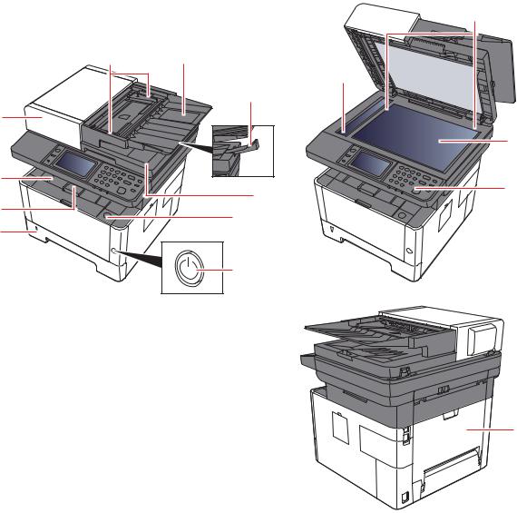
1-2 Part Names
(1) Machine Exterior
|
14 |
10 |
9 |
|
11 |
|
8 |
1 |
|
13
2 |
7 |
12 |
|
||
3 |
|
|
6 |
|
|
4 |
|
|
|
|
|
|
5 |
|
15
1 |
Document Processor |
9 |
Original Tray |
2 |
Inner Tray |
10 |
Original Width Guides |
3 |
Eject Stopper |
11 |
Slit Glass |
4 |
Cassette 1 |
12 |
Operation Panel |
5 |
Power Switch |
13 |
Contact glass |
6 |
Front Cover Open Button |
14 |
Original Size Indicator Plates |
7 |
Original Eject Table |
15 |
Rear cover |
8 |
Original Stopper |
|
|
1-7

2S0/2S1/2S2/2S3/2S4/2S5/2SG/2SH/3RA
(2) Connectors/Interior
1 2
3
4
12
5 |
11 |
|
6
8 |
9 |
10 |
7 |
1. |
TEL Connector |
7. |
Paper Width Guides |
|
2. |
LINE Connector |
8. |
USB Memory Slot |
|
3. |
USB Interface Connector |
|||
9. |
Multi Purpose Tray |
|||
4. |
Network Interface Connector |
10. |
Sub Tray |
|
5. |
Feed Cover |
11. |
Paper Guides |
|
6. |
Paper Length Guide |
12. |
Fuser Cover |
1-8
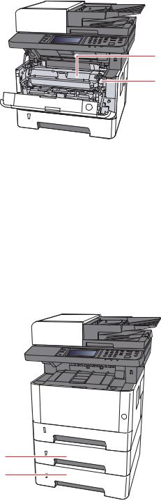
2S0/2S1/2S2/2S3/2S4/2S5/2SG/2SH/3RA
14
13
13.Toner Container Release Button
14.Toner Container
(3)With Optional Equipments Attached
1
2
1.Cassette 2
2.Cassette 3
1-9
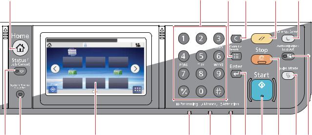
(4) Operation Panel (TSI)
1 |
|
Select the function. |
10:10 |
Home |
Admin |
Copy |
Send |
FAX |
|
Job Box |
Removable |
Sub |
|
Address |
|||
Memory |
|||
|
Box |
||
|
|
||
Status |
|
Task Screen |
2 |
3 |
4 |
2S0/2S1/2S2/2S3/2S4/2S5/2SG/2SH/3RA
17 |
16 |
15 |
14 |
13 |
5 |
6 |
7 |
8 |
9 |
10 |
11 |
12 |
1.[Home] key: Displays the Home screen.
2.[Status/Job Cancel] key: Displays the Status/Job Cancel screen.
3.[System Menu/Counter] key: Displays the System Menu/Counter screen.
4.Touch panel: Displays icons for configuring machine settings.
5.[Processing] indicator: Blinks while printing or sending/receiving.
6.[Memory] indicator: Blinks while the machine is accessing the machine memory or fax memory.
7.[Attention] indicator: Lights or blinks when an error occurs and a job is stopped.
8.[Enter] key: Finalizes numeric key entry, and finalizes details during setting of functions. Operates linked with the onscreen [OK].
9.[Start] key: Starts copying and scanning operations and processing for setting operations.
10.[Stop] key: Cancels or pauses the job in progress.
11.[Quiet Mode] key: Lower print and scan speed for quiet processing.
12.[Authentication/Logout] key: Authenticates user switching, and exits the operation for the current user (i.e. log out).
13.[Energy Saver] key: Puts the machine into Sleep Mode. Recovers from Sleep if in Sleep Mode.
14.[Reset] key: Returns settings to their default states.
15.[Clear] key: Clears entered numbers and characters.
16.[Quick No. Search] key: Specifies registered information such as address numbers and user IDs by number.
17.Numeric keys: Enter numbers and symbols.
1-10
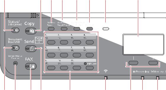
2S0/2S1/2S2/2S3/2S4/2S5/2SG/2SH/3RA
(5) Operation Panel Keys (LCD)
1 |
17 |
16 |
15 |
14 |
13 |
12 |
11 |
2 |
3 |
4 |
5 |
6 |
7 |
8 |
9 |
10 |
1.[Status/Job Cancel] key: Displays the Status/Job Cancel screen.
2.[Document Box/USB] key: Displays the Document Box/USB screen.
3.[System Menu/Counter] key: Displays the System Menu/Counter screen.
4.[FAX] key: Displays the FAX screen.
5.[Send] key: Displays the screen for sending. You can change it to display the Address Book screen.
6.One Touch keys: Recalls the destination registered for One Touch Keys.
7.[Wi-Fi] indicator : Blinks during Wi-Fi connection.
8.Select keys: Selects the menu displayed at the bottom of the message display.
9.[Processing] indicator: Blinks while printing or sending/receiving.
10.[Memory] indicator: Blinks while the machine is accessing the machine memory or fax memory.
11.Message display: Displays the setting menu, machine status, and error messages.
12.[Wi-Fi Direct] key: Set Wi-Fi Direct, and show information necessary for connection and the connection status.
13.[On Hook] key: Switches between on-hook and off-hook when manually sending a FAX.
14.[Confirm/Add Destination] key: Confirms the destination or adds a destination.
15.[Address Recall/Pause] key: Calls the previous destination. Also used to enter a pause when entering a FAX number.
16.[Address Book] key: Displays the Address Book screen.
17.[Copy] key: Displays the Copy screen.
1-11
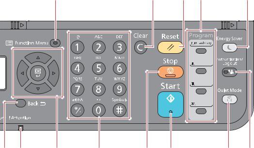
2S0/2S1/2S2/2S3/2S4/2S5/2SG/2SH/3RA
|
|
18 |
|
|
31 |
30 |
29 |
|
28 |
19 |
20 |
21, |
22 |
23 |
24 |
25 |
|
26 |
27 |
18.[Function Menu] key: Displays the function menu screen.
19.[Back] key: Returns to the previous display.
20.[Attention] indicator: Lights or blinks when an error occurs and a job is stopped.
21.Arrow keys: Increments or decrements numbers, or selects menu in the message display. In addition, moves the cursor when entering the characters.
22.[OK] key: Finalizes a function or menu, and numbers that have been entered.
23.Numeric keys: Enter numbers and symbols.
24.[Stop] key: Cancels or pauses the job in progress.
25.[Start] key: Starts copying and scanning operations and processing for setting operations.
26.[Quiet Mode] key: Lower print and scan speed for quiet processing.
27.[Authentication/Logout] key: Authenticates user switching, and exits the operation for the current user (i.e. log out).
28.[Energy Saver] key: Puts the machine into Sleep Mode. Recovers from Sleep if in Sleep Mode.
29.Program keys: Used to register or recall programs.
30.[Reset] key: Returns settings to their default states.
31.[Clear] key: Clears entered numbers and characters.
1-12
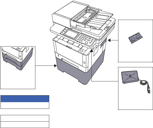
2S0/2S1/2S2/2S3/2S4/2S5/2SG/2SH/3RA
1-3 Overview of Optional Equipment
The following optional equipment is available for the machine.
(2) PF-1100 |
Software option
(4)UG-33
(5)SD/SDHC Memory Card
(6)USB Keyboad
(1) Expansion Memory
(3)Card Authentication Kit (B)
1-13
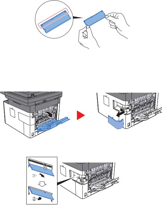
2S0/2S1/2S2/2S3/2S4/2S5/2SG/2SH/3RA
(1) Expansion Memory
The machine can perform the more multiple jobs simultaneously by adding more memories. You can increase the machine's memory up to 1,536 MB by plugging in the optional memory modules.
Precautions for Handling the Memory Modules
To protect electronic parts, discharge static electricity from your body by wearing an antistatic wrist strap, if possible, when you install the memory modules. If you do not have a wristband, touch a metal object to discharge static electricity before inserting the memory.
Installing the Memory Modules
1.Turn off the machine and disconnect the power cord and interface cable.
2.Remove the cover.
3.Remove the memory module from its package.
4.With the memory connection terminal pointing toward the socket, align the cut-out part with the socket terminal and insert directly in at an angle.
5.Carefully press the inserted memory down and into the machine.
6.Replace the covers.
1-14
Loading...