


|
© KROHNE 07/2002 |
7.02254.21.00 |
|
|
|
|
|
|
|
|
|
|
|
|
|
|
|
||
|
|
|
|
|
|
|
|||
|
|
|
|
|
|
|
|
|
|
|
|
|
|
|
|
|
|
|
|
|
|
|
|
|
|
|
|
|
|
|
|
|
|
|
|
|
|
|
|
Addition to the installation and
operating instructions
UFM 500 K - EEx ATEX
Ultrasonic compact flowmeter
Variable area flowmeters
Vortex flowmeters
Flow controllers
Electromagnetic flowmeters
Ultrasonic flowmeters
Mass flowmeters
Level measuring instruments
Communication technology
Engineering systems & solutions
Preasure and temperature

WARNING !
No changes may be made to the devices. Unauthorized changes might affect the explosion safety of the devices.
These additional instructions are an extension to the standard Installation and Operating Instructions and only applies for the EEx version of the UFM 500 K compact ultrasonic flowmeter. All technical information described in the standard Installation and Operating Instructions are applicable, when not specifically excluded or replaced by the instructions in these additional instructions.
CONTENTS
1. SYSTEM COMPONENTS ................................................................................................. |
2 |
|
1.1 |
GENERAL INFORMATION .................................................................................................... |
2 |
1.2 |
UFS 500-EEX PRIMARY HEAD .......................................................................................... |
2 |
1.3 |
UFC 500-EEX SIGNAL CONVERTER .................................................................................. |
3 |
|
1.3.1 Electronics compartment....................................................................................... |
3 |
|
1.3.2 Terminal compartment .......................................................................................... |
3 |
2. |
ELECTRICAL CONNECTION........................................................................................... |
4 |
|
2.1 POTENTIAL EQUALIZATION ................................................................................................ |
4 |
|
2.2 OPERATION OF THE SIGN AL CONVERTER........................................................................... |
5 |
3. |
CONNECTING CABLES.................................................................................................... |
5 |
4. |
CONNECTION DIAGRAM................................................................................................. |
6 |
5. |
SERVICE.............................................................................................................................. |
7 |
|
5.1 REPLACEMENT OF ELECTRONICS UNIT OR MAINS FUSE(S) ................................................. |
7 |
|
5.1.1 Replacement of electronics unit............................................................................ |
8 |
|
5.1.2 Replacement of mains fuse(s).............................................................................. |
8 |
|
5.1.3 Changing power supply voltage (not for 24 V AC/DC version).......................... |
11 |
6. |
SPARE PARTS ................................................................................................................. |
11 |
7. |
MAINTENANCE ................................................................................................................ |
11 |
8. |
EC-TYPE EXAMINATION CERTIFICATE .................................................................... |
12 |
9. |
DECLARATION OF CONFORMITY .............................................................................. |
16 |
10. DATA PLATE................................................................................................................... |
17 |
|
Be sure to follow these instructions !
IMPORTANT !
∙The prescriptions and regulations as well as the electrical data described in the EC type examination certificate must be obeyed.
∙Beside the instructions for electrical installations in non-hazardous locations according to the applicable national standard (equivalent of HD 384 or IEC 364, e.g. VDE 0100), especially the regulations in EN 60079-14 "Electrical installations in hazardous locations" or equivalent national standard (e.g. DIN VDE 0165 Part 1) must be strictly followed.
∙Installation, establishment, utilization and maintenance are only allowed to be executed by personnel with an education in explosion safety !
1

1. SYSTEM COMPONENTS
1.1 General information
The Altosonic UFM 500 K-EEx ultrasonic compact flowmeter is in accordance with the European Directive 94/9 EC (ATEX 100a) and approved for hazardous classified locations of Zone 1 and 2 by the PTB conform to the European Standards of the EN 500xx series. The UFM 500 K-EEx has the following approval number.
PTB 01 ATEX 2015 X
The UFM 500 K-EEx compact flowmeter is designed for ambient temperatures (i.e. Ta) in the range of -40°C up to +60°C. The maximum allowed process liquid (medium) temperature is restricted by the combustible atmosphere that (possibly) surrounds the apparatus, determined by the temperature class of the atmosphere, see Table 1 below.
|
Temperature class |
|
Maximum process liquid temperature |
|||||||
|
|
Ta ≤ 40°C |
|
|
Ta ≤ 50°C |
|
|
Ta ≤ 60°C |
|
|
|
|
|
|
|
|
|
|
|||
|
T6 |
80°C |
|
80°C |
|
80°C |
||||
|
T5 |
95°C |
|
95°C |
|
95°C |
||||
|
T4 |
130°C |
|
130°C |
|
125°C |
||||
|
T3 |
180°C |
|
165°C |
|
125°C |
||||
Table 1: Temperature classification of the UFM 500 K-EEx.
The UFM 500 K-EEx ultrasonic compact flowmeter consists of the UFC 500-EEx signal converter, which is screwed on top of the UFS 500-EEx primary head (i.e. measuring unit). The compact flowmeter is marked with one of the codes below:
Standard (default) version:
∙II 2G EEx de [ib] IIC T6…T3 for the terminal compartment of the signal converter housing in type of protection increased safety "e" according to EN 50019 (see also Section 1.3).
Optional version (only if explicitly ordered!):
∙II 2G EEx d [ib] IIC T6…T3 for the terminal compartment of the signal converter housing designed as flameproof enclosure "d" according to EN 50018 (see also Section 1.3)
1.2 UFS 500-EEx primary head
The UFS 500-EEx primary head is the measuring unit of the compact flowmeter and contains the ultrasonic sensors (a multiple of two opposite transducers) in type of protection intrinsic safety category "ib" according to EN 50020. All sensor circuits (only internal circuits) are wired by separate coaxial cables and connected through SMB connectors marked by number from 1 through 4. The UFC 500-EEx signal converter (described in the next section) is mounted on top of the primary head by four hexagon socket head cap screws size M6.
The intrinsically safe "ib" ultrasonic sensor circuits inside the UFS 500…-EEx primary head have the following maximum values (i.e. entity parameters):
∙ |
Maximum input voltage |
: Ui |
= 13.1 V |
∙ |
Maximum input current |
: Ii |
= 600 mA |
∙ |
Maximum internal capacitance |
: Ci |
= 7.7 nF (maximum, 2 sensor circuits) |
∙ |
Maximum internal inductance |
: Li |
= 134 µH (maximum, 2 sensor circuits) |
NOTE:
The intrinsical safe sensor circuits of the UFM 500K-EEx compact flowmeter are only internal circuits and not accessible for the customer. The above data (entity parameters) as well as in Section 1.3.1 on the next page are therefore for information only.
2

1.3 UFC 500-EEx signal converter
The UFC 500-EEx signal converter consists of a cylindrical housing made of die-casted aluminum. It has of two separate compartments, divided from each other by an integrated wall with casted flameproof terminal feed-through. The interconnecting part to the primary head at the bottom of the housing contains a flameproof wire or coaxial cable feed-through. The housing is closed on both ends by a cylindrical cover with M115x2-6g screw-thread and O-ring sealing. The signal converter housing has an ingress protection degree in accordance with the EN 60529 of at least IP 67. The two compartments are described in detail below.
1.3.1 Electronics compartment
The electronics compartment accommodates the UFC 500-EEx electronic unit. The compartment is designed with type of protection flameproof enclosure "d" in accordance with EN 50018. It is closed by a flameproof display cover with glass window, which is glued and additionally mechanical supported by a screwed in back-up ring made of aluminum.
The UFC 500-EEx electronics unit is inserted into the electronics compartment with the help of two sliding rubbers that position and fixate the unit at the front inside the housing. Two M4 screws mount the unit and a third M4 screw fixates the brass earth strip at the back-end of the printed circuit board with integrated voltage/current limiting circuit (i.e. front-end PCB). The three screws are screwed to the integrated wall in-between terminal and electronics compartment. The integrated voltage/current limiting circuit provides the ultrasonic sensors inside the primary head with type of protection intrinsic safety "ib" according to EN 50020.
The voltage/current limiting circuit has the following maximum values (i.e. entity parameters):
∙ |
Maximum output voltage |
: Uo = 8.72 V |
∙ |
Maximum output current |
: Io = 380 mA |
∙ Maximum allowed external capacitance |
: Co = 1.2 µF |
|
∙ Maximum allowed external inductance |
: Lo = 0.17 mH |
|
1.3.2 Terminal compartment
The terminal compartment accommodates seven M4 clamp terminals for connection of the power supply and the signal output circuits (binary and current outputs). Figure 1 on the next page shows the terminal arrangement. The terminals are separated from each other by insulation plates (nine in total, from which one at each end of the row).
In the following section the electrical connection of the mains supply power and the signal output circuits is described (this information only concerns the Ex-relevant subjects).
The terminal compartment (standard in type of protection increased safety "e") is standard equipped with two metal cable glands.
As an option (must be explicitly ordered!) the terminal compartment can be provided as a flameproof enclosure "d", in case the customer wants to use pre-certified "EEx d" cable glands or conduits.
Note: EEx d certified cable glands are no part of the standard delivery, they must be provided by the customer himself or ordered explicitly.
For flameproof conduit systems, the terminal compartment must have type of protection flameproof enclosure "d" according to EN 50018. The conduits must be sealed by "EEx d" approved (within the ATEX 100a directive) sealing devices (i.e. stopping box) directly at the conduit entrances of the as flameproof enclosure performed terminal compartment.
3

2. ELECTRICAL CONNECTION
NOTE:
All the connecting cables that enter the terminal compartment of the UFC 500-EEx signal converter (i.e. power supply, current and binary in-/outputs cables) are not intrinsically safe !
The arrangement of the terminals in the terminal compartment is shown in Figure 1 below.
For mains voltages above 50 Vac the PE conductor must be connected to the PE-terminal in the terminal compartment.
To connect external devices to the current and binary output terminals, the wiring requirements for the specific type of protection of the terminal compartment (standard: increased safety "e", special version: flameproof enclosure "d") must be respected, see the EN 60079-14 or corresponding national standard.
2.1 Potential equalization
The UFM 500 K-EEx ultrasonic compact flowmeter must always be connected to the equipotential bonding system of the hazardous area. For this purpose the internal PEterminal (over the PE-conductor of the mains) or the external PE-terminal may be used.
The external PE-terminal is placed halfway converter housing and primary head.
A separate bonding conductor must be at least 4 mm2, or 2,5 mm2 if mechanical protected, see clause 413 of HD 384.4.41or IEC 364-4-41 for additional information.
When the UFM 500 K-EEx is incorporated in the equipotential bonding system, make sure that the core of the bonding wire is properly mounted under the U-clamp of the PE-terminal and that the screw is tightly fixed.
Pulse |
Status |
output |
output |
B1 |
B |
B2 |
BINARY
OUTPUTS
I+ |
I |
L |
CURRENT |
L~ |
|
|
||
OUTPUT |
|
|
N (100…240V AC / 48…63 Hz)
L~ (24V AC/DC)
PE (Protective Earth) terminal
FE (Functional Earth) terminal
Figure 1: Arrangement of terminals in terminal compartment.
4
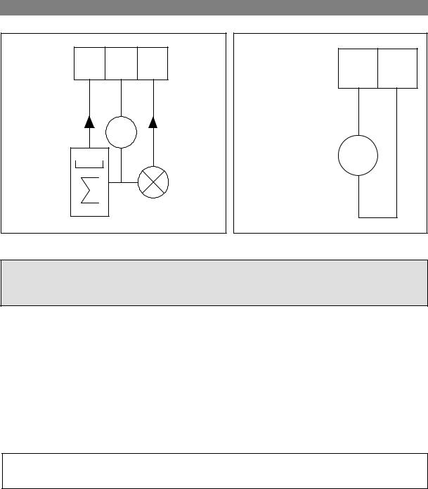
B1 B B2
I ≤ 150 mA |
Uext |
I ≤ 150 mA |
||
~ |
||||
|
|
|
||
Electronic |
000 |
|
|
|
or |
|
|
||
|
|
e.g. signal |
||
electro- |
|
|
||
mechanical |
|
|
indicator |
|
totalizer |
|
|
|
|
Uext ≤ 32VDC/24 VAC
Figure 2: Passive pulse/status output.
I+ I
+
Ri ≤ 680Ω mA
_
Figure 3: Active current output.
NOTE:
The status output (terminals B1, B^ and B2) can only be configured as passive outputs, the current output (terminals I+ and I) can only be configured as active output.
2.2 Operation of the signal converter
The UFC 500-EEx signal converter unit of the UFM 500 K-EEx compact flowmeter is equipped with a display unit that contains magnetic Hall sensors. These Hall sensors enable the settings of the UFC 500-EEx signal converter electronics to be set resp. reset with the help of the with the apparatus delivered bar magnet without opening the flameproof signal converter housing in the hazardous area. Consult the standard Installation and Operating Instructions (Part B) for the program functions of the software of the UFC 500-EEx electronics unit.
3. CONNECTING CABLES
NOTE:
The below described cables are shown in the connection diagram on the following page.
Cable A:
Signal cable for current output and binary in-/outputs (pulse and status output). This cable type must be in accordance with clause 9 of the EN 60079-14 "Electrical installations in hazardous locations" or an equivalent national standard (e.g. DIN VDE 0165 Part 1).
Cable B:
Mains power supply cable. This cable type must also be in accordance with clause 9 of the EN 60079-14 "Electrical installations in hazardous locations" or an equivalent national standard (e.g. DIN VDE 0165).
Rated voltage: |
³ 500 V |
Examples: |
H07..-., H05..-. to HD 21.S2 or HD22.S2 |
Separate bonding conductor
Minimum cross-sectional area: |
4 mm2 |
|
|
|
5 |
 Loading...