


© KROHNE 06/2005 |
DIN A4: 7.10028.31.00 |
|
|
|
|
|
|
|
|
|
|
|
|
|
|||
7.30935.32.00 |
|
|
|
|
|
|
|
|
|
|
|
|
|
|
|
||
|
|
|
|
|
|
|
|
|
 GR
GR
Service Handbook
Universal 3-Beam ultrasonic flowmeter
UFM 3030 K/…EEx compact ultrasonic flowmeter
UFC 030 F/…EEx ultrasonic flow converter
UFS 3000 F/…EEx ultrasonic flow sensor
Electromagnetic flowmeters
Variable area flowmeters
Mass flowmeters
Ultrasonic flowmeters
Vortex flowmeters
Flow controllers
Level measuring instruments
Pressure and temperature
Heat metering
Communications technology
Switches, counters, displays and recorders
Engineering systems & solutions
Subject to change without notice.
General advice on safety
•Do not install, operate or maintain this flow meter without reading, understanding and following the factory-supplied instructions, otherwise injury or damage may result.
•Read these instructions carefully before starting installation and save them for future reference.
•Observe all warnings and instructions marked on the product.
•Use only mains supply with protective earthing connected.
•Do not use the product with removed covers under wet conditions.
•Consider handling and lifting instructions to avoid damage.
•Install the product securely and stable.
•Install and connect cabling proper to exclude damage or harmful situations.
•If the product does not operate normally, refer to the service instructions or refer to qualified KROHNE service engineers.
•There are no operator-serviceable parts inside the product.
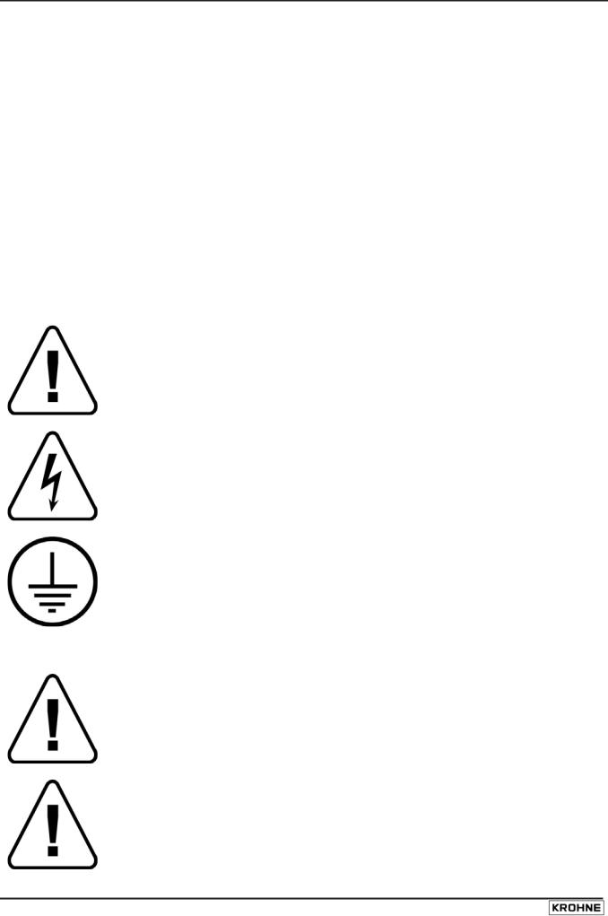
The following symbols may appear in this manual or on the product
ATTENTION: refer to operating and installation instructions!
DANGER: risk of electric shock!
PROTECTIVE conductor terminal!
These terms may appear in this manual or on the product:
WARNING statement: identify conditions or practice that could result in injury or loss of life.
CAUTION statement: identify conditions or practice that could result in damage to the product or other property.
2 |
UFM 3030 |

Disclaimer
•This document contains important information on the product. KROHNE attempts to be as accurate and up-to-date as possible but assumes no responsibility for errors or omissions. Nor does KROHNE make any commitment to update the information contained herein. This manual and all other documents are subject to change without prior notice.
•KROHNE will not be liable for any damage of any kind by using its product, including, but not limited to direct, indirect, incidental, punitive and consequential damages.
•This disclaimer does not apply in case KROHNE has acted on purpose or with gross negligence. In the event any applicable law does not allow such limitations on implied warranties or the exclusion of limitation of certain damages, you may, if such law applies to you, not be subject to some or all of the above disclaimer, exclusions or limitations.
•Any product purchased from KROHNE is warranted in accordance with the relevant product documentation and our Terms and Conditions of Sale.
•KROHNE reserves the right to alter the content of its documents, including this disclaimer in any way, at any time, for any reason, without prior notification, and will not be liable in any way for possible consequences of such changes.
Product liability and warranty
•Responsibility for suitability and intended use of this ultrasonic flow meter rests solely with the user. Improper installation and operation of the flow meter (system) may lead to loss of warranty.
•In addition, the Terms and Conditions of Sale are applicable and are the basis for the purchase contract.
•If flow meters need to be returned to KROHNE, please note the information given on the last pages of the installation and operating instructions. KROHNE regrets that they cannot repair or check flow meter(s) unless accompanied by the completed form (see last pages of the installation and operating instructions).
Items included with order
•UFM 3030 ultrasonic flow meter, comprising of a flow sensor, UFS 3000 and a signal converter, UFC 030 either built together as a compact system or supplied as two separate pieces, in the size as indicated on the packaging box
•Signal cable (only in case of a separate system)
•Special tool for opening the converter housing
Documentation supplied
•Condensed installation and operating manual
•For Ex-units: installation and operating instructions for use in hazardous areas
•Instruction card: overview of the configuration menu and display markers
•Product information CD
•Approval documents, unless reproduced in the installation and operating instructions
•Certificate of system calibration data
UFM 3030 |
3 |

This instrument is developed and manufactured by:
KROHNE Altometer
Kerkeplaat 12
3313 LC Dordrecht
The Netherlands
For information, maintenance or service please contact your nearest local KROHNE representative.
Notes on the service handbook
This service handbook is divided into four parts for easy use. All ultrasonic flow meters are factoryset to your order specifications. Therefore, no further adjustments are necessary prior to initial startup. Condensed installation and operating instructions are available for installation and initial start-up.
Part A |
Chapters 1, 2 and 3; System installation and start-up. Installation, connecting and |
|
powering the flow meter. |
Part B |
Chapters 4 and 5; The signal converter. Operator control and functioning of the |
|
signal converter. |
Part C |
Chapters 6 and 7; Functional checks and service. Servicing the flow meter. |
Part D |
Chapters 8, 9 and 10; Technical data. dimensions, block diagram and ultrasonic |
|
measuring principle. |
4 |
UFM 3030 |

Table of contents |
|
|
1 |
Introduction |
6 |
1.1 |
Cautions |
6 |
1.2 |
Unpacking and inspection |
6 |
1.3 |
System description |
6 |
1.4 |
Available versions |
7 |
1.5 |
CE Approvals |
7 |
2 |
Mechanical installation |
8 |
2.1 |
Handling the flowmeter |
8 |
2.2 |
Installation location and position |
8 |
2.3 |
Special installation requirements |
9 |
2.4 |
Pipe flanges |
10 |
2.5 |
Pipes with cathodic protection |
11 |
3 |
Connecting the signal converter |
12 |
3.1 |
Safety instructions |
12 |
3.2 |
Converter terminal box |
12 |
3.3 |
Power supply connection |
12 |
3.4 |
Connection of sensor cables (UFM 3030 F only) |
13 |
3.5 |
Electrical connection of the signal inputs and outputs |
14 |
3.6 |
Connection diagram examples |
16 |
4 |
Start-up |
17 |
5 |
Operating the signal converter |
18 |
5.1 |
Front panel and operating keys |
18 |
5.2 |
Menu structure and function of operating keys |
19 |
6 |
Description of functions |
28 |
6.1 |
Menu structure |
28 |
7 |
Functional checks |
40 |
7.1 |
Test functions of the signal converter Function 2.1 to 2.5 |
40 |
7.2 |
Measuring zero flow value |
41 |
8 |
Service and Repair |
42 |
8.1 |
Replacement of electronic unit of signal converter |
42 |
8.2 |
Replacement of ultrasonic flow sensor in separate systems |
42 |
8.3 |
Change of power supply fuse |
43 |
8.4 |
Cleaning |
44 |
8.5 |
Turning the display circuit board |
44 |
8.6 |
Turning the signal converter housing |
44 |
9 |
Returning the flow meter for service or repair |
45 |
10 |
Dimensions |
46 |
11 |
Block diagram |
46 |
12 |
Ultrasonic measurement principle |
47 |
12.1 |
Transit time differential method |
47 |
12.2 |
Three beam ultrasonic measurement |
47 |
|
|
|
|
UFM 3030 |
5 |
Part A System Installation and Start-up
1 Introduction
1.1Cautions
Only for flow meters supplied with a voltage over 50 VAC.
Refer all maintenance or service to trained KROHNE service engineers.
Mains power shall be disconnected from the product before performing any maintenance.
This product is prepared for and can only function with the rated AC mains voltage as indicated on the nameplate.
This product is a Class 1 device (earthed) and requires a correct connection to protective earth. The protective earth conductor of the main power shall be properly connected to the marked protective earth terminal to ensure safety from electric shock for the operator and its environment. For detail refer to this service handbook.
1.2Unpacking and inspection
•This product has been thoroughly inspected and tested before shipment and is ready for operation.
•After carefully unpacking, inspect for shipping damage before attempting to operate. If any indication of mechanical damage is found contact immediately the responsible transport service and your local KROHNE representative.
•A simple operating check of the electronics after unpacking and before permanent installation is advisable to ascertain whether it has suffered damage during shipment. Confirm for the correct mains voltage printed on the nameplate. If it differs from the ordered product please contact your local KROHNE representative.
•After connecting to the mains, check if there is any indication on the display and if the backlight of the display is lighted. If not, contact your local KROHNE representative for advice.
1.3System description
The UFM 3030 ultrasonic flow meter is a precision instrument designed for linear, bi/directional flow measurement of liquids. Flow measurement values can be output via the standard analog and-or pulse/frequency outputs. Via a user friendly operator interface (HMI) the unit can be set up for a wide range of applications. Next to actual volumetric flow measurement the unit can be configured to perform flow totalization (plus, minus and sum). Also measurement and output of the liquid sonic velocity can be configured. Optionally the unit can be set to perform one of the following additional functions:
•Calculate and output corrected standard volumetric or mass flow using the external pressure and temperature inputs
•Batch function
•Heat function, combining T1, T2 and volume
6 |
UFM 3030 |
1.4Available versions
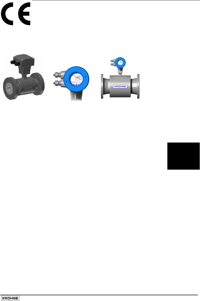
The UFM 3030 consists of a flow sensor (UFS 3000) and a signal converter (UFC 030), which can be built into a compact flow meter, UFM 3030 K or a separate flow meter, UFM 3030 F.
Both flow sensor and signal converter are available with an approval for use in hazardous areas. Special codes and regulations apply in these areas and are referred to in the instructions for hazardous area versions, supplied as a separate manual.
UFS 3000 |
UFC 030 |
UFM 3030 K |
1.5CE Approvals
EMC, Electromagnetic Compatibility Directive
The product complies with the requirements of the harmonised standards under the EMC directive 89/336/EEC.
Low Voltage Directive
The product complies with the requirements of the Low Voltage Directive 73/23/EEC and is designed in accordance with EN IEC 61010-1 first and second edition. (safety requirements for electrical equipment for measurement, control and laboratory use part 1)
Local safety regulations shall be observed in combination with the measures special to this product to avoid dangerous situations.
Pressure Equipment Directive
The KROHNE organisation complies with the requirements of Module H of the Pressure Equipment Directive 97/23/EC (full quality assurance).
Please refer to the CE declaration for more detailed information.
UFM 3030 |
7 |
2 Mechanical installation
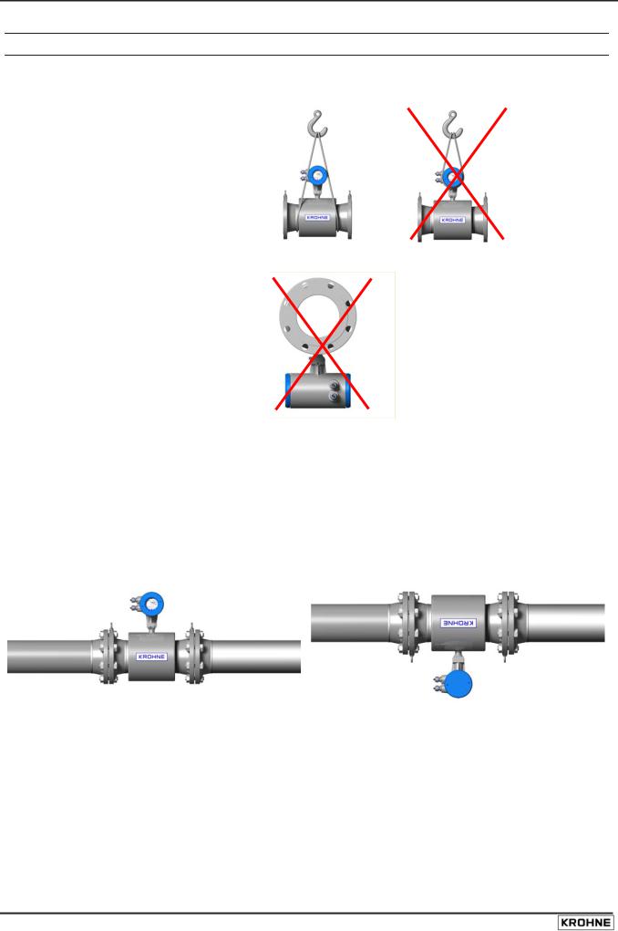
2.1Handling the flowmeter
Important: Do not lift the compact flowmeter by the signal converter housing or the terminal box. Check the weight of the flowmeter as indicated on the type plate before handling the unit. When handling the flowmeter avoid hard blows, jolts or impacts.
Do not place the flowmeter on the signal converter housing.
2.2Installation location and position
The UFM 3030 flow meter can be installed in horizontal, slightly ascending or vertical pipelines. If installed in a horizontal or slightly ascending pipeline, always install the converter or terminal box in vertical position opposite the flow sensor either with the converter up or down, but never in horizontal position.
8 |
UFM 3030 |
If required the position of the signal converter can be modified by turning the display circuit board through 90° or 180° to achieve a horizontal position of the display. In addition the signal converter housing may be turned through 90° opposite the flow sensor.
For an exact description of this procedure, refer to chapter 8.6.
The measuring tube must be completely filled at all times for proper flow measurement, as the sensors become non-wetted, a loss of signal message will be displayed. There is no damage when this occurs.
Flow direction. The UFM 3030 is a bi-directional flow meter. Note the indicating arrow for the positive direction on the flow meter.
It is recommended to protect the signal converter from direct sunlight to prolong the life. Although no direct damage will occur, installation of a sunshield is advised.
Do not expose the signal converter to excessive vibration. To protect the flow meter from excessive vibration support the pipeline on either side of the flow meter.
Make sure there is sufficient room next to the pipe flanges to fit the bolts and nuts.
To achieve the specified accuracy of the flow meter, a straight inlet section of 10 × DN (DN = meter size) and an outlet section of 5 × DN should be applied.
Normally zero setting is not necessary, but if required the zero point can be checked and the meter can be re-zeroed under stationary flow conditions (see Function 1.01.03 of the converter menu). To force zero flow, a shut-off valve should be provided upstream and/or downstream of the flow sensor.
Mixing different fluid products. Install the flow meter upstream of mixing point or at minimum distance of 30× DN (DN = meter size) downstream of the mixing point, otherwise the flow measurement may be unstable.
Ambient temperature all flow meters: -40 to +65°C/ -40 to +149°F
Product temperature compact flow meter: -25 to +140°C/ -13 F to +284°F
Product temperature separate flow meter: -25 to +180°C/ -13 to +356°F
Special versions are available for higher process temperatures.
In case of a pipeline running along a wall: please observe a minimum distance between pipe centreline and the wall of at least 0.5 m (1.6 ft).
2.3Special installation requirements
To avoid measuring errors and malfunctioning of the flow meter due to gas or air inclusions or an empty pipe, please observe the following precautions:
UFM 3030 |
9 |
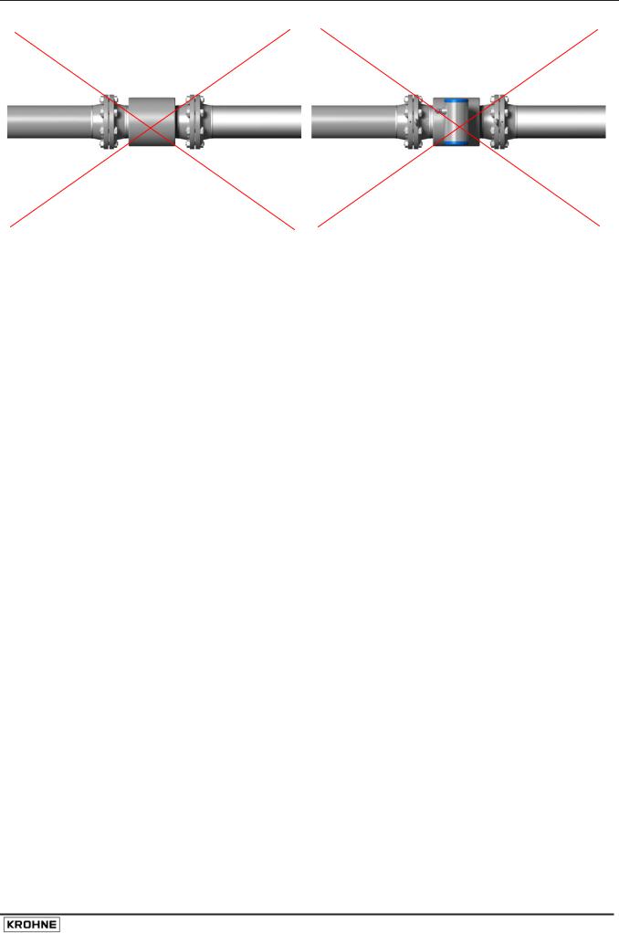
Since gas will collect at the highest point of a pipe, installation of the flow meter at that location should be avoided at all times. Also installation in a down going pipe should be avoided since a completely filled pipe may not be guaranteed due to cascading affects. Additionally flow profile distortion is possible.
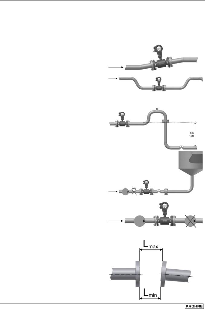
Long horizontal pipes: install in slightly ascending pipe section. If not possible, ensure adequate velocity to prevent air, gas or vapour from collecting in upper part of flow tube As a partially filled meter will report higher than actual flow rates, or not measure (as transducer pairs become non-wetted).
Open feed or discharge: Install meter in a lowered section of the pipe to ensure a full pipe condition through the meter.
Down going pipeline over 5 m (16 ft) length: install air vent downstream of the flow meter. To prevent vacuum. While this will not harm the meter, it may cause gases to come out of solution (cavitate) and interfere with proper measurements.
Always install control valves downstream of flow meter in order to avoid cavitation or distortion of flow profile.
Never install flow meter on a pump suction side in order to avoid cavitation or flashing in the flow meter.
2.4Pipe flanges
Refer to dimensional drawings for flange spacing and in addition allow for thickness of gaskets. Install flow meter in line with pipe axis. Pipe flange faces must be parallel to each other, max. Permissible deviation: Lmax - Lmin ≤ 0.5 mm (0.02").
10 |
UFM 3030 |
2.5Pipes with cathodic protection
Pipes with electric corrosion protection are generally insulated inside and outside so that the fluid has no conductive connection to ground. The flow meter must be insulated from the pipe. Note the following when installing the flow meter:
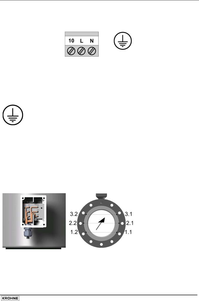
The pipe flanges must be connected to each other using a copper cable (L), but must not be connected to the flow meter.
The bolts for the flange connections and the gaskets must be insulated. Use sleeves and washers that are made of insulating material (these must be provided by customer).
1.Flange of flow sensor
2.Gasket
3.Pipe flange
4.Bolt
5.Nut
6.Washer
7.Insulating sleeve
Follow grounding instructions.
Use ≥ 4 mm2 (≥ AWG 10 cable).
Note: No earthing cables are supplied by
KROHNE.
UFM 3030 |
11 |
3 Connecting the signal converter
3.1Safety instructions
This product is designed for use in accordance with EN IEC 61010-1 for Installation Category 2 and Pollution Degree 2. Hazardous voltages are present within this product during normal operation. The product is designed for Protection Class I and should never be operated without protective earthing. The product shall also never be operated with covers removed unless equivalent protection of the operator and its environment from accidental contact with hazardous internal voltages is provided. Always follow basic and local safety precautions when using this product to reduce risk of injury from electrical shock, spread of fire or other dangerous situations.
3.2Converter terminal box
•The converter terminal box is accessible after removing the rear (blind) cover of the electronics section using the special wrench supplied with the flow meter.
•Do not damage the screw thread and the gasket, never allow dirt to accumulate, and make sure that the screw thread is well greased, using Teflon grease at all times. A damaged gasket must be replaced immediately!
•Do not cross or loop the cables in the terminal box of the signal converter. Use separate cable entries for power supply and signal cables.
•Special regulations apply to installation in hazardous areas (see installation instructions for hazardous areas).
3.3Power supply connection
In case of connection to the mains supply voltage:
Environmental conditions
•The UFM3030 is designed to operate safe under the following conditions:
•Suitable for indoor and outdoor use, the instrument is usable up to protection category IP67 (IEC 60529)
•Use up to an altitude of 2000 m above see level
•Suitable for an operation ambient temperature range -40°C to +65°C
• Suitable for an storage temperature range -40°C to + 80°C
•Suitable for use in atmospheres with a relative humidity up to 80%
•Over voltages up to category II on the main supply voltage ( IEC 60364-4-443)
•Connected to protective earth conductor ( Protection Class I)
•Rated pollution degree 2
•This instrument is intended for permanent connection to the mains. It is required (for example for service) to mount an external switch or circuit breaker near the product for disconnection from the mains. It must be easily reachable by the operator and marked as the disconnecting device for this product.
The switch or circuit breaker has to be suitable for the application and shall also be in accordance with to local (safety) requirements and of the building installation. (IEC 60947-1/-3).
•The protective conductor clamp terminal size M5, press-fitted in the terminal compartment (near the main connection terminals), shall always to be connected to the protective earth conductor of the mains supply. Conductors up to 4 mm² (11 AWG) be connected to this terminal. The diameter of the conductors of the mains supply, including the protective earth conductor shall be in accordance with the general and local requirements.
12 |
UFM 3030 |
• It is not allowed to use the protective conductor terminal for any other connection than the protective earth conductor.
• IP 67 is only warranted when using suitable cabling with the cable glands and
|
covers mounted as specified. |
|
The power supply terminals |
There is a separate earthing |
|
has three connections |
that must be connected: |
|
|
|
: |
Terminal |
Function |
Specification |
10 |
Reserved Ground connection |
Not for protective earthing |
L / L1 |
Live power supply |
Mains voltage AC supply: |
|
|
100 V AC < U < 240 V AC: -15%, +10% |
|
|
SELV AC/DC supply: |
|
|
DC: 18-32 V dc |
N / N1 |
Neutral power supply |
AC: 24 V AC: -10% +15% |
|
||
|
PE: Protective ground connection |
Protective conductor clamp terminal. |
|
FE: Functional ground connection |
Conductors up to 4 mm² (11 AWG) need |
|
|
to be connected to this terminal. |
3.4Connection of sensor cables (UFM 3030 F only)
For the UFM 3030 F the sensors must be connected using the factory supplied MR06 cable between the flow sensor terminal box and the converter housing terminal box. For the UFM 3030C this is connected at the factory.
Both the flow sensor terminals and the converter sensor terminals should be connected using the appropriate numbers indicated on the sensor cable.)
Cable diameter: 11 mm (0,433 inch), minimum bending radius: 8 x cable diameter.
UFM 3030 |
13 |
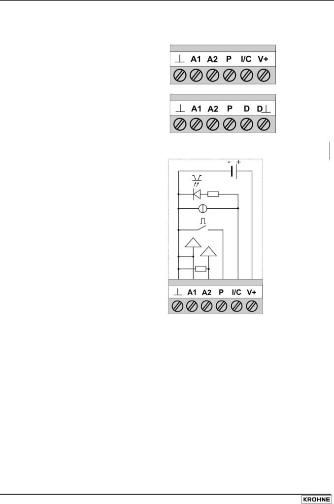
3.5Electrical connection of the signal inputs and outputs
The terminal to connect the electrical signal inputs and outputs consist of 6 connections.
For standard instruments
For instruments with a communication module
For wiring of the signal inputs and outputs it is advised to use unshielded twisted pairs.
Internal circuit of the signal inputs and outputs of the converter
Terminal |
Function |
|
Common ground |
A1 |
Analog input 1, for temperature |
|
measurement. Configuration via menu |
|
option 3.2.2. and 3.2.3. |
A2 |
Analog input 2, for temperature or |
|
pressure measurement. Configuration |
|
via menu option 3.2.4. and 3.2.5. |
I/C |
Combined Current output (I) and |
|
Digital input (C). |
|
Current output (I) Incl. Hart |
|
communication |
|
Function can be set via menu option |
|
3.4.0. and 3.6.0. |
PPulse/frequency output. Function can be set via menu option 3.5.0.
V+ |
DC power supply from converter for |
|
active wiring of inputs and outputs |
Specification
-
0(4) to 20 mA Ri = 58,2 Ω, fuse: 50 mA 0(4) to 20 mA Ri = 58,2 Ω, fuse: 50 mA
Current output (I): I ≤ 22 mA, Rload ≤ 680 Ω. Umax = 15Vdc.
Digital input (C): low = 0-5 VDC, high = 1532 VDC. Will be switched off when current output activated.
I max: 150 mA Umax: 32Vdc, 24Vac Max frequency: 2 kHz
22 VDC at full load, 24 VDC maximum. I ≤ 100 mA.
14 |
UFM 3030 |

D+ |
Communication connection+ |
For fieldbus communication |
D- |
Communication connection - |
For fieldbus communication |
P/I/C |
Combined current output (I) digital |
See individual I/C terminal and P terminal |
|
output (C) and pulse output (P). See |
specifications. |
|
individual I/C terminal and P terminal |
|
|
functions |
|
The electrical input and output signals can be connected either in active or in passive mode. In active mode DC supply voltage is provided from the V+ terminal. In passive mode supply voltage is provided from an external source. Please observe instrument polarity: current (I) is always flowing towards I, C, P, A1, A2 terminals (current sink).
Note! Never use the active and passive mode at the same terminal simultaneously.
If HART communication is used, do not connect the pulse/frequency output P in active mode.
UFM 3030 |
15 |
 Loading...