


TM-3000

TM-3000
Setup guide
This guide describes the basic operations for TM-3000.
For operation details, see "User's Manual".
High-speed 2D Measurement Sensor
I
Introduction
Wiring
Installation
P 2
P 2
I -1
I -2
II
Operational Flow for Measurement
Operational flow for measurement
II
-1
III
Measurement – diameter and step height of a stepped shaft
Diameter measurement
Step height measurement
Measuring the outer diameter of a target
Measuring the step height of a target
III
-1
III
-2
IV
Settings/Operations Used for All Measurements
Master registration
Measurement setting
Area setting
Registering an image to be used as a measurement standard
Making detailed measurement settings
Specifying measurement points
IV
-1
IV
-2
IV
-3
V
Position correction
Measuring correcting the margin of error
caused by the position change of the target
V
-1
VI
Frequently Used Settings
External Trigger
Offset
Scaling
Tolerance
Initialization
Measuring synchronizing with the external signal input
Setting the displayed value to an arbitrary value
Correcting measured values
Making the tolerance setting
Restoring the default status
VI
-1
VI
-2
VI
-3
VI
-4
VI
-5
VII
Settings for Data Saving
Data storage function
Excel transfer function
Image storage function
Image capture function
Storing measurement data
Displaying the storage data on the Excel file
Saving the image data of measurement targets
Saving the monitor images
VII
-1
VII
-2
VII
-3
VII
-4
P 3
P 9
P 6
P 7
P 8
P10
P10
P11
P11
P11
P12
P13
P14
P15
P 4
P 5
Setting for Correcting the Position of the Target
96M11229

2
I -
11
Manual P1-18
This section explains the wiring and installation of this unit.
Wiring
I -
22
Manual P1-11
Installation
Introduction
I
To obtain the measurement image in the best condition, place the measurement target at the focus mark
indicated on the TR base.
Make wiring and connection for this unit as illustrated below.
Target
Introduction
ReceiverTransmitter
Focus mark
TR base
Console
Head B
Controller
24 VDC power supply
Head A
Head-to-controller cable
(0.7 m/2 m/5 m/10 m/20 m/30 m)
TM-3000
POWER
ON
CON
SOLE
I/O
OU
T
MONITOR
HEAD-B
HEAD-A
ETHERNET
RS-232C
USB
S
D CARD
Monitor

3
II -
11
Operational flow for measurement
Manual P5-37
This section explains settings required to perform measurement.
This measurement sensor measures outer diameters or the distances based on the edge information
(boundary of a bright and a dark part of the image) of measured images.
For detailed measurement content, specify the “Measurement type” in the “Measurement setting” and set.
Set the target within the measurement area and perform the
master registration.
Select the measurement type according to the measured content.
(The “Measurement type” can be selected in the measurement setting.)
Setting procedure
Step 1
Step 2
Measurement types T
Diameter :
Maximum diameter
Intersection (X and Y coordinates)
Intersection
distance
Distance between point
and straight line
Y position (Y axis)
X position (X axis)
Step height :
Step height
Width :
Minimum diameter
Width
Angle
Radius
Roundness
Pitch
Manual
P5-43
Manual
P5-48
Manual
P5-52
Y position :
X position :
Coordinate :
Manual
P5-46
Manual
P5-50
Manual
P5-63
Distance :
Intersection distance :
Area :
Manual
P5-54
Manual
P5-56
Manual
P5-65
Angle :
Manual
P5-58
Radius :
Roundness :
Manual
P5-60
Manual
P5-62
Pitch :
Manual
P5-70
Diameter, step height, width
The maximum diameter and minimum diameter
within the specified range, and step height and
width between detected edges are measured.
Angle
This measures the angle made by the detected
two straight lines or the tilt from the arbitrary line.
Radius, roundness
This measures the radius of specified arc
and the roundness.
Pitch
This measures the maximum, minimum or
average pitch within the specified range.
Y position, X position, coordinate
Y position, X position of detected edge, or
coordinate at the specified point is measured.
Distance, intersection distance, area
This measures the distance between the specified two
points, such as distance between center of circle and
intersection, and also measures the area.
Operational Flow for Measurement
Operational Flow for Measurement
II
Area
Tilt from the arbitrary line
* If position change, etc. occurs for the measurement target, use the position correction
function (page 9 in this manual).
The measurement area is corrected by the amount of change and the target
measurement is taken.
Distance between the centers of two targets

4
III
-
11
Manual P5-43
Make the detailed settings for each OUT.
Measure the diameter for OUT1 and step height for OUT2 respectively.
Perform the master registration beforehand for this measurement.
For setting the master registration, see page 6 in this manual.
Slide the [PROG/RUN] switch on the side of the console to
display the settings screen (screen 1).
The screen switches from the measurement screen to the setting
screen.
Select “Measure set” on screen 1.
Press the [ENTER] key on the console to select the item.
Select “OUT1” on screen 2.
Select “Diameter” in “Measurement type” on screen 3
Select “Area 1” and set the area vertically long.
For area operation, see page 8 in this manual.
Confirm the “Measured content” is set to “Average” and “Tilt
corr” is set to “ON”.
* Setting the tilt correction (Tilt corr) to “ON” enables the diameter to
be measured correctly even if the target has a tilt.
Press the [ESCAPE] key on the console to return to screen 2.
The diameter measurement setting (1) is complete.
This measures the stepped shaft.
Diameter measurement
XXX
Measuring the outer diameter of a target
(1) Diameter
measurement
(2) Step height measurement
Setting procedure
Screen 2
Screen 3
Screen 1
III
I
I
I
I
1
2
3
4
5
6
1
2
3
4
5
Measurement – diameter and step height of a stepped shaft
Measurement – diameter and step height of a stepped shaft
5
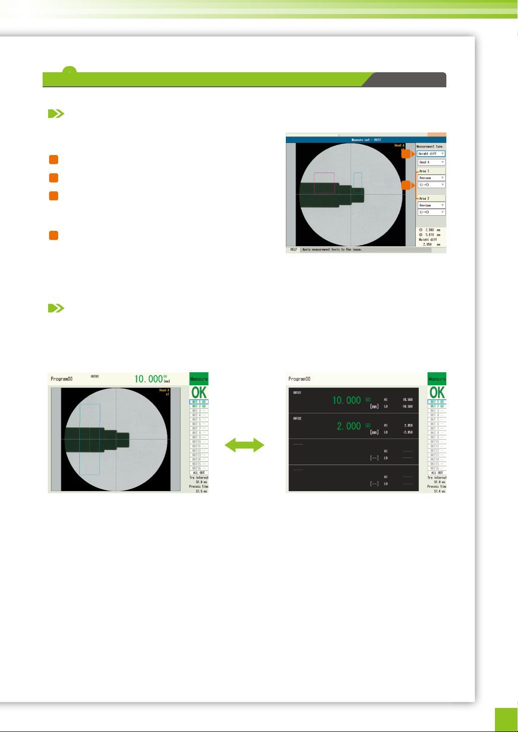
Select OUT2 on screen 2 and make the setting for measuring (2) the step height.
Sliding the [PROG/RUN] switch on the side of the console switches from the setting screen to the
measurement screen.
The measurement results for (1) Diameter and (2) Step Height are displayed.
To set scaling or tolerance for measurement values, see page11 in this manual.
Select “OUT2” on screen 2 on the previous page.
Select “Step Height” for “Measurement type” on screen 4.
Select “Area 1/Area 2” on screen 4 and set the area as
shown on screen 4.
For area operation, see page 8 in this manual.
Press the [ESCAPE] key on the console to return to screen 1.
The step height measurement setting (2) is complete.
* To measure correcting the tilt, see the position correction function (page 8 in this manual).
Pressing the [SCREEN] key
switches the screen according
to each setting.
Screen 4
III
-
22
Manual P5-48
Step height measurement
XXX
Measuring the step height of a target
Setting procedure
Checking the measurement status
[SCREEN]
8
9
7
8
9
10
 Loading...