


COMPACT VHS CAMCORDER
GR-AXM900
Please visit our CyberCam Homepage on the World Wide Web and answer our Consumer Survey (in English only):
http://www.jvc-victor.co.jp/index-e.html
Compact VHS
For Customer Use:
Enter below the Model No. and Serial
No. which is located on the bottom of
INSTRUCTIONS cabinet. Retain this information for future reference.
Model No.
Serial No.
LYT0055-001A
2
 EN
EN


Dear Customer,
Thank you for purchasing the JVC Compact VHS camcorder. Before use, please read the safety information and precautions contained in the following pages to ensure safe use of your new camcorder.
Using This Instruction Manual
•All major sections and subsections are listed in the Table Of Contents (Z pg. 8, 9).
•Notes appear after most subsections. Be sure to read these as well.
•Basic and advanced features/operation are separated for easier reference.
It is recommended that you . . .
..... refer to the Index (Z pgs. 74 – 79) and familiarize yourself with button locations, etc. before use.
..... read thoroughly the Safety Precautions and Safety Instructions that follow. They contain extremely important information regarding the safe use of your new camcorder.
You are recommended to carefully read the cautions on pages 83 – 85 before use.
SAFETY
PRECAUTIONS
CAUTION
RISK OF ELECTRIC SHOCK
DO NOT OPEN
CAUTION: TO REDUCE THE RISK OF ELECTRIC SHOCK.
DO NOT REMOVE COVER (OR BACK). NO USER-SERVICEABLE PARTS INSIDE.
REFER SERVICING TO QUALIFIED SERVICE PERSONNEL.
The lightning flash with arrowhead symbol, within an equilateral triangle, is intended to alert the user to the presence of uninsulated "dangerous voltage" within the product's enclosure that may be of sufficient magnitude to constitute a risk of electric shock to persons.
The exclamation point within an equilateral triangle is intended to alert the user to the presence of important operating and maintenance (servicing) instructions in the literature accompanying the appliance.
The AA-V15U AC Power Adapter/Charger should be used with:
AC 120 V`, 60 Hz in the USA and Canada, AC 110 – 240 V`, 50/60 Hz in other countries.
CAUTION (applies to the AA-V15U)
TO PREVENT ELECTRIC SHOCK MATCH WIDE BLADE OF PLUG TO WIDE SLOT, FULLY INSERT.
ATTENTION (s’applique à l’AA-V15U)
POUR ÉVITER LES CHOCS ÉLECTRIQUES, INTRODUIRE LA LAME LA PLUS LARGE DE LA FICHE DANS LA BORNE CORRESPONDANTE DE LA PRISE ET POUSSER JUSQU’AU FOND.
WARNING:
TO PREVENT FIRE OR SHOCK HAZARD, DO NOT EXPOSE THIS UNIT TO RAIN OR MOISTURE.
Warning on lithium battery
The battery used in this device may present a fire or chemical burn hazard if mistreated. Do not recharge, disassemble, heat above 100°C (212°F) or incinerate.
Replace the battery with Maxell, Panasonic (Matsushita Electric), Sanyo or Sony CR2025; use of another battery may present a risk of fire or explosion.
nDispose of used battery promptly.
nKeep away from children.
nDo not disassemble and do not dispose of in fire.
NOTES:
cThe rating plate (serial number plate) and safety caution are on the bottom and/or the back of the main unit.
cThe rating plate (serial number plate) of the AC Power Adapter/Charger is on its bottom.
This Class B digital apparatus meets all requirements of the Canadian Interference – Causing Equipment Regulations.
“Cet appareil numérique de la classe B respecte toutes les exigences du Règlement sur le matériel brouilleur du Canada.”
This camcorder is designed to be used with NTSCtype color television signals. It cannot be used for playback with a television of a different standard.
However, live recording and LCD monitor/viewfinder playback are possible anywhere. Use the BN-V11U/V12U/V22U/V25U battery packs and, to recharge them, the provided multi-voltage AC Power Adapter/Charger. (An appropriate conversion adapter may be necessary to accommodate different designs of AC outlets in different countries.)
ATTENTION:
The product that you have purchased is powered by a rechargeable battery. The battery is recyclable. At the end of its useful life, under various state and local laws, it may be illegal to dispose of this battery into the municipal waste stream. Check with your local solid waste officials for details in your area for recycling options or proper disposal.

IMPORTANT PRODUCT SAFETY INSTRUCTIONS
Electrical energy can perform many useful functions. But improper use can result in potential electrical shock or fire hazards. This product has been engineered and manufactured to assure your personal safety. In order not to defeat the built-in safeguards, observe the following basic rules for its installation, use and servicing.
ATTENTION:
Follow and obey all warnings and instructions marked on your product and its operating instructions. For your safety, please read all the safety and operating instructions before you operate this product and keep this manual for future reference.
INSTALLATION
1. Grounding or Polarization
(A)Your product may be equipped with a polarized alternating-current line plug (a plug having one blade wider than the other). This plug will fit into the power outlet only one way. This is a safety feature.
If you are unable to insert the plug fully into the outlet, try reversing the plug. If the plug should still fail to fit, contact your electrician to replace your obsolete outlet. Do not defeat the safety purpose of the polarized plug.
(B)Your product may be equipped with a 3-wire grounding-type plug, a plug having a third (grounding) pin. This plug will only fit into a grounding-type power outlet. This is a safety feature.
If you are unable to insert the plug into the outlet, contact your electrician to replace your obsolete outlet. Do not defeat the safety purpose of the grounding-type plug.
2. Power Sources
Operate your product only from the type of power source indicated on the marking label. If you are not sure of the type of power supply to your home, consult your product dealer or local power company. If your product is intended to operate from battery power, or other sources, refer to the operating instructions.
3. Overloading
Do not overload wall outlets, extension cords, or integral convenience receptacles as this can result in a risk of fire or electric shock.
4. Power Cord Protection
Power supply cords should be routed so that they are not likely to be walked on or pinched by items placed upon or against them, paying particular attention to cords at plugs, convenience receptacles, and the point where they exit from the product.


 EN
EN 3
3
5. Ventilation
Slots and openings in the cabinet are provided for ventilation. To ensure reliable operation of the product and to protect it from overheating, these openings must not be blocked or covered.
•Do not block the openings by placing the product on a bed, sofa, rug or other similar surface.
•Do not place the product in a built-in installation such as a bookcase or rack unless proper ventilation is provided or the manufacturer’s instructions have been adhered to.
6. Wall or Ceiling Mounting
The product should be mounted to a wall or ceiling only as recommended by the manufacturer.
ANTENNA INSTALLATION
INSTRUCTIONS
1. Outdoor Antenna Grounding
If an outside antenna or cable system is connected to the product, be sure the antenna or cable system is grounded so as to provide some protection against voltage surges and built-up static charges. Article 810 of the National Electrical Code, ANSI/NFPA 70, provides information with regard to proper grounding of the mast and supporting structure, grounding of the lead-in wire to an antenna discharge unit, size of grounding conductors, location of antenna discharge unit, connection to grounding electrodes, and requirements for the grounding electrode.
2. Lightning
For added protection for this product during a lightning storm, or when it is left unattended and unused for long periods of time, unplug it from the wall outlet and disconnect the antenna or cable system. This will prevent damage to the product due to lightning and power-line surges.
3. Power Lines
An outside antenna system should not be located in the vicinity of overhead power lines or other electric light or power circuits, or where it can fall into such power lines or circuits. When installing an outside antenna system, extreme care should be taken to keep from touching such power lines or circuits as contact with them might be fatal.
EXAMPLE OF ANTENNA GROUNDING AS PER
NATIONAL ELECTRICAL CODE, ANSI/NFPA 70
ANTENNA
LEAD IN WIRE
GROUND CLAMP
ANTENNA DISCHARGE UNIT
(NEC SECTION
ELECTRIC SERVICE 810-20) EQUIPMENT 

GROUNDING CONDUCTORS (NEC SECTION 810-21)
GROUND CLAMPS
POWER SERVICE GROUNDING ELECTRODE SYSTEM (NEC ART 250. PART H)
NEC – NATIONAL ELECTRICAL CODE

4
 EN
EN


USE
1. Accessories
To avoid personal injury:
•Do not place this product on an unstable cart, stand, tripod, bracket or table. It may fall, causing serious injury to a child or adult, and serious damage to the product.
•Use only with a cart, stand, tripod, bracket, or table recommended by the manufacturer or sold with the product.
•Use a mounting accessory recommended by the manufacturer and follow the manufacturer’s instructions for any mounting of the product.
•Do not try to roll a cart with small casters across thresholds or deep-pile carpets.
2. Product and Cart Combination
A product and cart combination should be moved with care. Quick stops, excessive force, and uneven surfaces may cause the product and cart combination to overturn.
3. Water and Moisture
Do not use this product near water—for example, near a bath tub, wash bowl, kitchen sink or laundry tub, in a wet basement, or near a swimming pool and the like.
PORTABLE CART WARNING (Symbol provided by RETAC)
4. Object and Liquid Entry
Never push objects of any kind into this product through openings as they may touch dangerous voltage points or short-out parts that could result in a fire or electric shock. Never spill liquid of any kind on the product.
5. Attachments
Do not use attachments not recommended by the manufacturer of this product as they may cause hazards.
6. Cleaning
Unplug this product from the wall outlet before cleaning. Do not use liquid cleaners or aerosol cleaners. Use a damp cloth for cleaning.
7. Heat
The product should be situated away from heat sources such as radiators, heat registers, stoves, or other products (including amplifiers) that produce heat.
SERVICING
1. Servicing
If your product is not operating correctly or exhibits a marked change in performance and you are unable to restore normal operation by following the detailed procedure in its operating instructions, do not attempt to service it yourself as opening or removing covers may expose you to dangerous voltage or other hazards. Refer all servicing to qualified service personnel.
2. Damage Requiring Service
Unplug this product from the wall outlet and refer servicing to qualified service personnel under the following conditions:
a.When the power supply cord or plug is damaged.
b.If liquid has been spilled, or objects have fallen into the product.
c.If the product has been exposed to rain or water.
d.If the product does not operate normally by following the operating instructions. Adjust only those controls that are covered by the operating instructions as an improper adjustment of other controls may result in damage and will often require extensive work by a qualified technician to restore the product to its normal operation.
e.If the product has been dropped or damaged in any way.
f.When the product exhibits a distinct change in performance—this indicates a need for service.
3. Replacement Parts
When replacement parts are required, be sure the service technician has used replacement parts specified by the manufacturer or have the same characteristics as the original part. Unauthorized substitutions may result in fire, electric shock or other hazards.
4. Safety Check
Upon completion of any service or repairs to this product, ask the service technician to perform safety checks to determine that the product is in safe operating condition.


 MAJOR
MAJOR FEATURES


 EN
EN 5
5
REMEMBER
The Logical Choice
Program Manager II (Z pg. 28 – 41)
Program AE with Special Effects, Fade/Wipe, Wide, Super LoLux, Instant Title, Menu Adjustment (Focus, Exposure Control and so on.)
 The only compact video cassettes that can be
used with your VHS VCR*
Program AE with Special Effects (Z pg. 28, 29)
nAuto Mode Lock
nAuto Mode Release
nElectronic Fog Filter
nND Effect
nSepia
nTwilight
nSports
nNega/Posi
n1/2000 sec. High Speed Shutter
LCD Color Monitor (Z pg. 20)
90°
180°
Digital Still Camera Built-in (PC communication capable) (Z pg. 48 – 63)
Integrated Auto Light (Z pg. 25)
Picture Stabilizer (Z pg. 23)
Digital Hyper Zoom (Z pg. 22)
Zoom-in
Zoom-out
Cassettes marked  can be used with this camcorder.
6
 EN
EN


 QUICK
QUICK
 OPERATION

 GUIDE
GUIDE

 (VIDEO)


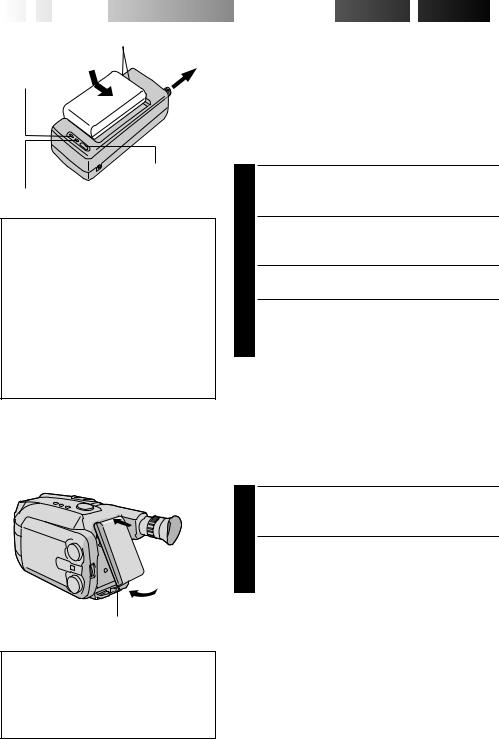
SUPPLY POWER
Hook on.
1
2Push in.
BATT. RELEASE
Using the battery pack
1Hook-on the battery pack’s top end to the camcorder. (Charging procedure, Z pg. 10)
2Push in the battery pack until it locks into place.
To remove the battery pack
Slide BATT. RELEASE and pull out the battery pack.
INSERTING A VIDEO
CASSETTE
PUSH |
EJECT |
|
2 |
4 |
3 |
1Open
1 Open the LCD monitor to an angle of over 45 degrees.
2 Press EJECT to open the cassette holder.
3 Insert a video cassette.
4Press PUSH to close the cassette holder. (For more details, Z pg. 17)
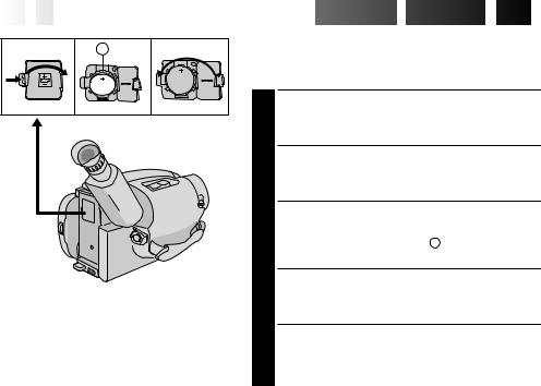
PLAYBACK
PLAY/PAUSE 4 STOP
1Set to “VIDEO”
3 REW
Set to “PLAY”2
1 Set the System Select Switch to “VIDEO”.
2 Set the Power Switch to “PLAY”.
3Press REW.
—The tape will automatically stop at the beginning of the tape.
4Press PLAY/PAUSE.
—Playback starts and the playback picture appears.
•To stop playback, press STOP. (For more details, Z pg. 42.)
•The viewfinder switches off automatically to save power when the LCD monitor is opened at an angle of over 45 degrees.
•The LCD monitor turns on/off when it is opened/closed at approx. 45 degrees.
Or simply play back the tape on a VHS VCR
using the Cassette Adapter (VHS Playpak). Z pg. 45
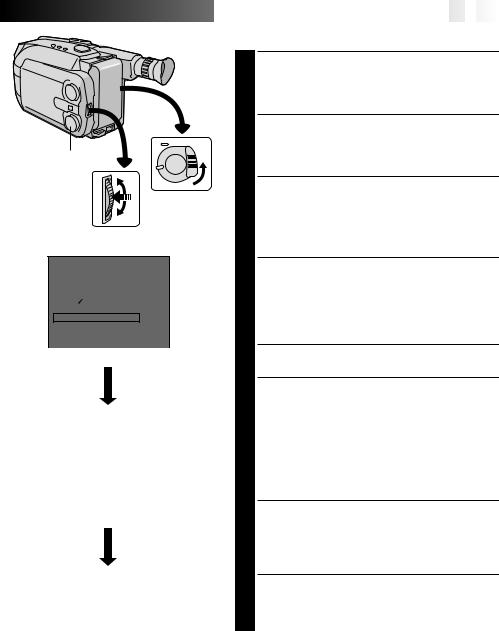
SHOOTING
1 LENS COVER
Open/Close Set to Switch “VIDEO”
2
4
|
Recording |
|
Start/Stop |
3 |
Button |
Set to |
|
“CAMERA” |
|
1Slide the LENS COVER Open/Close Switch to open the lens cover.
2 Set the System Select Switch to “VIDEO”.
3 Set the Power Switch to “CAMERA”.
—The power indicator will light and an image will appear.
4Press the Recording Start/Stop Button.
— Recording starts.
•To stop recording temporarily, momentarily press the Recording Start/Stop Button once
again.
(For more details, Z pgs. 18 – 21)
•The viewfinder switches off automatically to save power when the LCD monitor is opened at an angle of over 45 degrees.
•The LCD monitor turns on/off when it is opened/closed at approx. 45 degrees.
 QUICK
QUICK
 OPERATION
 GUIDE
GUIDE


 (D.S.C.)


 EN
EN 7
7
SUPPLY POWER |
SHOOTING |
|
|
Hook on. |
4 SNAPSHOT Button |
||
1 |
|||
|
|
||
|
|
1 |
|
2Push in. |
|
LENS COVER |
|
|
Open/Close |
||
|
|
||
|
3 |
Switch |
|
|
|
||
BATT. RELEASE |
Power Switch |
|
|
|
Set to “CAMERA” |
||
Using the battery pack
1Hook-on the battery pack’s top end to the camcorder. (Charging procedure, Z pg. 10)
2Push in the battery pack until it locks into place.
To remove the battery pack
Slide BATT. RELEASE and pull out the battery pack.
PLAYBACK

 3 Page Button

 2
2
Power Switch
Set to “PLAY”
1System Select Switch Set to “D.S.C.”
1Set the System Select Switch to “D.S.C.”.
2Set the Power Switch to “PLAY”.
—A still image stored in memory appears. 3Press “W” or “T” of the Page Button to select
the still image you want to view. (For more details, Z pg. 55.)
•The viewfinder switches off automatically to save power when the LCD monitor is opened at an angle of over 45 degrees.
•The LCD monitor turns on/off when it is opened/closed at approx. 45 degrees.
2
System Select Switch Set to “D.S.C.”
1Slide the LENS COVER Open/Close Switch to open the lens cover.
2 Set the System Select Switch to “D.S.C.”.
3Set the Power Switch to “CAMERA”.
—The power indicator will light and an image will appear.
4Press the SNAPSHOT Button.
—A still image is shot and is stored in the camcorder’s memory.
(For more details,
•The viewfinder switches off automatically to save power when the LCD monitor is opened at an angle of over 45 degrees.
•The LCD monitor turns on/off when it is opened/closed at approx. 45 degrees.

8
 EN
EN


 CONTENTS


GETTING STARTED |
10 |
Power ..................................................................................... |
10 |
Clock (Lithium) Battery Insertion/Removal .......................................... |
12 |
Date/Time Setting ....................................................................... |
13 |
Grip Adjustment ......................................................................... |
14 |
Viewfinder Adjustment ................................................................. |
14 |
Shoulder Strap Attachment ............................................................. |
15 |
Tripod Mounting .......................................................................... |
15 |
Recording Mode Setting ................................................................ |
16 |
Tape Length Setting ..................................................................... |
16 |
Loading/Unloading A Cassette ........................................................ |
17 |
VIDEO RECORDING |
18 |
Basic Recording .......................................................................... |
18 |
Basic Features ............................................................................ |
22 |
Advanced Features ...................................................................... |
28 |
VIDEO PLAYBACK |
42 |
Basic Playback ........................................................................... |
42 |
Features ................................................................................... |
44 |
Using The Cassette Adapter ............................................................ |
45 |
BASIC CONNECTIONS TO VCR |
46 |
TAPE DUBBING |
47 |
DIGITAL STILL CAMERA (D.S.C.) SHOOTING |
48 |
Basic Shooting ............................................................................ |
48 |
Advanced Features ...................................................................... |
50 |
D.S.C. PLAYBACK |
55 |
Basic Playback ........................................................................... |
55 |
Advanced Features ...................................................................... |
56 |
Connection ................................................................................ |
63 |
USING REMOTE CONTROL UNIT |
64 |
Random Assemble Editing .............................................................. |
66 |
Insert Editing ............................................................................. |
70 |
Audio Dubbing ............................................................................ |
72 |
|
EN 9 |
USER MAINTENANCE |
73 |
INDEX |
74 |
LCD monitor/Viewfinder Indications .................................................. |
75 |
Controls ................................................................................... |
76 |
Connectors ................................................................................ |
76 |
Indicators ................................................................................. |
76 |
Other Parts ............................................................................... |
76 |
Terms ...................................................................................... |
78 |
TROUBLESHOOTING |
80 |
CAUTIONS |
83 |
SPECIFICATIONS |
86 |
OPTIONAL ACCESSORIES |
86 |
ESPAÑOL |
87 |
FOR SERVICING (Only in U.S.A.) |
90 |
WARRANTY (Only in U.S.A.) |
91 |
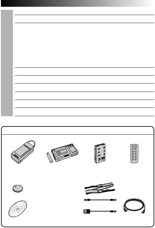
PROVIDED ACCESSORIES |
|
•AC Power Adapter/ |
• Cassette Adapter |
• Battery Pack |
•Remote Control |
Charger AA-V15U |
(VHS Playpak) C-P7U |
BN-V11U |
Unit RM-V705U |
•Lithium Battery |
|
|
|
CR2025 x 2 |
|
• Shoulder Strap |
|
(for clock operation |
|
||
|
|
||
and remote control unit) |
|
|
|
•CD-ROM including two |
(for Macintosh®) |
|
|
|
|
||
software programs |
|
|
|
|
|
(for Windows®) |
|
|
|
•PC Connection Cable x 2 |
• DC Cord |
10

 EN
EN


Marks
To AC outlet
CHG. (charge) indicator
REFRESH switch
REFRESH indicator
REFRESH
The AC power adapter features a REFRESH function that allows you to fully discharge the battery pack before recharging.
Perform the REFRESH function after no less than 5 chargings.
To discharge the battery . . .
..... attach the battery pack to the adapter as shown in the above illustration. Then push REFRESH. The REFRESH indicator lights when discharging starts, and goes out when discharging is complete.


 GETTING

 STARTED


Power
This camcorder’s 3-way power supply system lets you choose the most appropriate source of power.
NOTES:
cNo function is available without power supply.
cUse only specified power supply.
cDo not use provided power supply units with other equipment.
CHARGING THE BATTERY PACK
SUPPLY POWER
1 Connect the charger’s AC power cord to a wall outlet.
ATTACH BATTERY PACK
2 Align the marks and slide the battery pack in the direction of the arrow until it locks in place.
•The CHG. indicator begins blinking to indicate charging has started.
DETACH BATTERY PACK
3 When the CHG. indicator stops blinking but stays lit, charging is finished. Slide the battery pack opposite the direction of the arrow.
BATT. PACK |
CHARGE |
DISCHARGE |
|
|
|
BN-V11U |
approx. 1 hr. 10 min. |
approx. 3 hrs. 30 min. |
|
|
|
BN-V12U |
approx. 1 hr. 10 min. |
approx. 3 hrs. 30 min. |
|
|
|
BN-V22U |
approx. 2 hrs. 10 min. |
approx. 7 hrs. |
|
|
|
BN-V25U |
approx. 2 hrs. 40 min. |
approx. 10 hrs. |
|
|
|
Hook on.
 1
1
2 Push in.
BATT. RELEASE
ATTENTION:
Before detaching the power source, make sure that the camcorder’s power is turned off. Failure to do so can result in a camcorder malfunction.
USING THE BATTERY PACK
ATTACH BATTERY PACK
1 Hook its top end to the camcorder and push the battery pack in until it locks in place.
DETACH BATTERY PACK
2 Slide BATT. RELEASE and pull out the battery pack.
Approximate recording time (unit: min.)
|
LCD |
|
LCD |
LCD |
BATT. |
monitor on/ |
monitor off/ |
monitor on/ |
|
PACK |
Viewfinder off |
Viewfinder on |
Viewfinder on |
|
BN-V11U |
50 (35) |
50 (35) |
40 (30) |
|
|
|
|
|
|
BN-V12U |
50 (35) |
50 (35) |
40 (30) |
|
|
|
|
|
|
BN-V22U |
105 |
(70) |
110 (75) |
90 (65) |
|
|
|
|
|
BN-V25U |
140 |
(100) |
150 (105) |
125 (90) |
|
|
|
|
|
( ) : when the video light is on.


 EN
EN 11
11

CHARGE MARKER

 Charge marker A charge marker is provided on the battery pack to help you remember whether it has been charged or not. Two colors are provided (red and black)—you choose which one means charged and which means discharged.
NOTES:
cThe recording time per charge is affected by such factors as the time spent in Record-Standby mode and the frequency of zooming. It is safer to have spare battery packs.
cCharging times noted on page 10 are for fully discharged battery pack, and discharging times are for fully charged battery pack.
cCharging and discharging times vary according to the ambient temperature and the status of the battery pack.
cRemember to set the charge marker after charging a battery pack or after detaching a discharged one from your camcorder.
cPerform the REFRESH function after no less than 5 chargings.
cWhile the AC Power Adapter/Charger’s power cord is disconnected from the AC outlet, it is possible to discharge the battery by pressing the REFRESH switch. During that time, the AC Power Adapter/Charger does not charge the battery. When disharging is complete, detach the battery from the AC Power Adapter/ Charger to store it.
cHigh temperatures can damage the battery pack, so use only where good ventilation is available. Don’t allow it to discharge in container, such as a bag.
cIf you stop recharging or discharging part way through, make sure to remove the battery pack before unplugging the adapter’s AC cord.
cRemove the battery pack from the adapter immediately after discharging.
cTo avoid interference with reception, do not use the AC Power Adapter/Charger near a radio.
cMake sure you unplug the DC cord before charging or discharging the battery pack.
cThe CHG. indicator may not light properly with a brand new battery pack, or with one that’s been stored for an extended period. In this case, remove and reattach the battery pack and recharge it. The CHG. indicator should blink during recharging. If not, contact your nearest JVC dealer.
To AC outlet
DC OUT terminal
To DC
IN jack
|
AC Power |
|
Adapter/Charger |
DC cord |
AA-V15U |
To car’s cigarette
lighter socket
Car Battery Cord
AP-V7U (optional)
USING A CAR BATTERY
Use the optional Car Battery Cord or Car Battery Charger/Adapter (connect as shown in the illustration to the left).
NOTES:
cWhen using the car battery, leave the engine idling.
cThe optional Car Battery Charger (BH-V3U) can also be used to charge the battery pack.
cWhen using the optional Car Battery Charger or Car Battery Cord (AP-V7U), refer to the respective instruction booklet.
USING AC POWER
Use the AC Power Adapter (connect as shown in the illustration to the left).
NOTE:
|
The supplied AC Power Adapter/Charger features |
|
Car Battery Charger/Adapter |
automatic voltage selection in the AC range from |
|
110 V to 240 V. |
||
BH-V3U (optional) |
||
|
12

 EN
EN


 GETTING
 STARTED
 (cont.)


A |
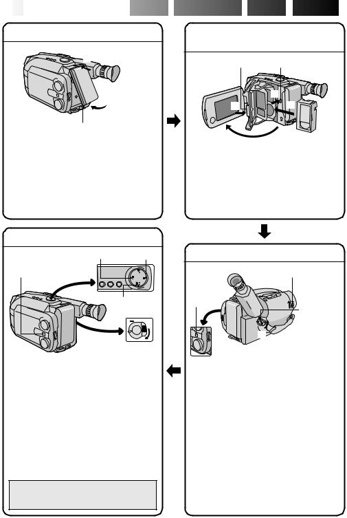
Clock (Lithium) Battery Insertion/Removal
This battery is necessary for clock operation and to perform date/time settings.
SWITCH OFF POWER
1 Switch off the unit’s power and remove the power supply unit.
OPEN COVER
2 Open the clock battery compartment cover while pressing the release tab.
REMOVE BATTERY (when replacing)
3 Insert a pointed, non-metallic object between the battery and the compartment ( A ) and pull the battery out.
INSERT BATTERY
4 Ensure that the plus (+) side is up and insert a CR2025 lithium battery and push it in.
CLOSE COVER
5 Close the compartment cover until it clicks in place.
NOTE:
See “SAFETY PRECAUTIONS” (Z pg. 2) for information on safe handling of lithium batteries.
Select Dial
MENU
Jog Dial
LCD monitor or viewfinder
MENU
|
4MENU END |
AUTO |
||||||||||
|
FOCUS |
|||||||||||
|
EXPOSURE |
AUTO |
||||||||||
|
DATE TIME |
|
JAN 1. 98 |
|||||||||
|
TELE |
MACRO |
|
OFF |
||||||||
|
TAPE LENGTH |
T30 |
|
|
||||||||
|
M. W. B. |
AUTO |
|
|||||||||
|
ZOOM SPEED |
FAST |
|
|||||||||
|
4NEXT |
|
|
|
|
|
|
|
|
|||
|
|
Menu Screen |
|
|||||||||
|
|
|
|
|
|
|
|
|||||
|
|
|
|
|
When the System |
|||||||
|
|
|
|
|
Select Switch is set to |
|||||||
|
|
|
|
|
“D.S.C.”, “PICTURE” |
|||||||
|
|
|
|
|
is displayed. |
|||||||
|
|
|
|
|
|
|
|
|
||||
|
|
DATE TIME |
|
|
|
|||||||
|
|
|
|
|
|
|
|
|
|
|
||
|
YEAR |
1998 |
|
|
|
|||||||
|
MONTH |
|
|
JAN |
|
|
|
|
|
|||
|
DAY |
|
|
|
1 |
|
|
|
|
|
||
|
TIME |
|
|
PM 12:00 |
|
|
|
|
||||
|
EXIT |
|
|
|
|
|
|
|
|
|
|
|
DATE/TIME Setting Menu |
|
|||||||||||
|
|
|
|
|
|
|
|
|
||||
|
|
|
|
|
12-hour indication |
|||||||
|
|
|
|
|
with AM or PM |
|||||||
|
|
|
|
|
|
|
|
|
|
|
|
|
|
|
MENU |
|
|
|
|
|
|
|
|
||
|
|
|
|
|
|
|
|
|
|
|
|
|
|
4MENU END |
AUTO |
|
|
|
|||||||
|
FOCUS |
|
|
|
|
|||||||
|
EXPOSURE |
AUTO |
|
|
||||||||
|
DATE TIME |
DEC 25. 98 |
|
|
||||||||
|
TELE |
MACRO |
OFF |
|
|
|||||||
|
TAPE LENGTH |
T30 |
|
|
||||||||
|
M. W. B. |
AUTO |
|
|
||||||||
|
ZOOM SPEED |
FAST |
|
|
||||||||
|
4NEXT |
|
|
|
|
|
|
|
|
|||


 EN
EN 13
13

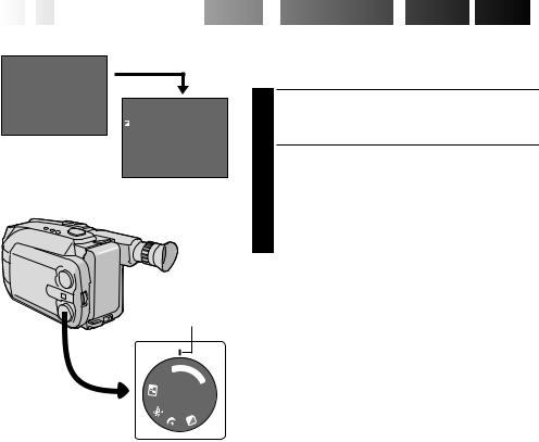
Date/Time Setting
ACCESS MENU SCREEN
1 First set the Power Switch to “CAMERA”. Turn the Select Dial to any position except AUTO LOCK, then press the MENU Jog Dial.
SELECT FUNCTION
2 Rotate the MENU Jog Dial to move the highlight bar to “DATE/TIME”, then press it. The DATE/TIME Setting Menu appears.
•If you decide you want to return the date and time to the previous settings, rotate the MENU Jog Dial to move highlight bar to “EXIT” and press it, then go to step 6.
•If you want to set only the time without changing the date, go to step 4.
SET DATE
3 Rotate the MENU Jog Dial to move the highlight bar to the item you want to set and then press it. When the setting begins blinking, rotate the MENU Jog Dial until the correct setting appears and then press it. The setting stops blinking.
•Repeat this procedure until you’re satisfied with the Date settings (“YEAR”, “MONTH” and “DAY”).
SET TIME
4 Rotate the MENU Jog Dial to move the highlight bar to “TIME” and then press it. When the hour setting begins blinking, rotate the MENU Jog Dial until the correct setting appears and then press it. When the hour setting stops blinking and the minute setting begins blinking, rotate the MENU Jog Dial until the correct setting appears and then press it. The minute setting stops blinking.
START CLOCK OPERATION
5 When none of these settings (YEAR, MONTH, DAY, TIME) blinks, rotate the MENU Jog Dial to move the highlight bar to “EXIT”, and press it. The Menu Screen appears and “MENU END” is highlighted.
CLOSE MENU
6 Press the MENU Jog Dial.
NOTE:
To display the date and time in the LCD monitor or the viewfinder and on a connected TV, see “Date/Time Insert” (Z pg. 24).
14EN |
GETTING STARTED (cont.) |
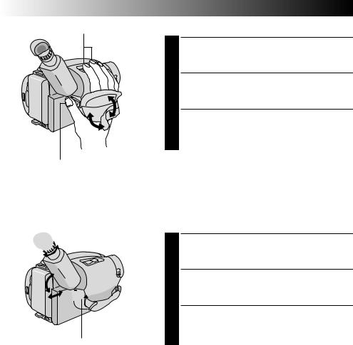
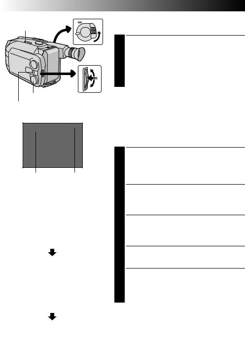
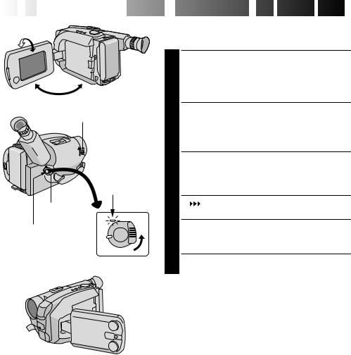
Power Zoom Button |
Grip Adjustment |
|
EXPAND LOOP |
|
1 Separate the Velcro strip. |
|
INSERT HAND |
|
Pass your right hand through the loop and grasp the |
|
2 grip. |
|
ADJUST STRAP LENGTH |
|
Adjust so your thumb and fingers can easily operate |
|
3 the Recording Start/Stop Button and Power Zoom |
|
Button. Refasten the Velcro strip. |
Recording Start/Stop Button
 3
3
1

 2
2
Set POWER to “CAMERA”.
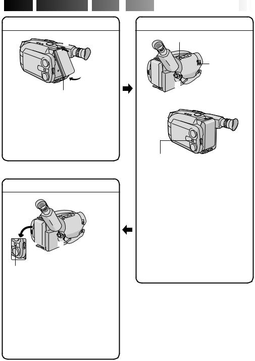
Viewfinder Adjustment
POSITION VIEWFINDER
1 Adjust the viewfinder manually for best viewability (see illustration at left).
SELECT MODE
2 Set the Power Switch to CAMERA.
ADJUST DIOPTER
3 Turn the Diopter Adjustment Control until the indications in the viewfinder are clearly focused.
|
EN 15 |
|
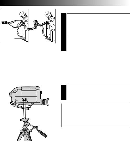
Shoulder Strap Attachment |
|
ATTACH STRAP |
|
Following the illustration at left, thread the strap |
2 |
1 through the top of the eyelet 1, then fold it back |
and thread it through the buckle 2. Repeat the |
|
1 |
procedure to attach the other end of the strap to the |
|
other eyelet 3, making sure the strap isn’t twisted. |
3 |
ADJUST LENGTH |
|
2 Adjust as shown in the illustration at left 1. |
Tripod Mounting
ALIGN AND TIGHTEN
1 Align the screw and camera direction stud on the tripod with the camera’s mounting socket and stud hole. Then tighten the screw.
CAUTION:
When using a tripod, be sure to open and extend its legs fully to stabilize the camcorder. To prevent damage to the unit caused by falling over, do not use a small-sized tripod.
16EN |
|
VIDEO GETTING STARTED |
|
SP/EP Recording |
|
Recording Mode Setting |
|
Mode Button |
|
Set depending on your preference. |
|
|
|
SET RECORDING MODE |
|
|
|
First set the System Select Switch to “VIDEO”, then |
|
|
|
1 set the Power Switch to “CAMERA”. Press SP/EP |
|
|
|
Button for more than 1 second. “SP” (Standard Play) |
|
|
|
provides higher picture and sound quality and is |
|
|
|
better for dubbing, while “EP” (Extended Play) is |
|
|
|
more economical, providing three times as the |
|
|
|
recording time. |
|
Select Dial |
MENU Jog Dial |
NOTE: |
|
System Select Switch |
If the recording mode is switched during recording, the |
||
|
|||
|
playback picture will be blurred at the switching point. |
||
|
|
||
Viewfinder |
|
|
T40
SP
Recording mode |
|
Tape length |
|||||
indicator |
|
indicator |
|||||
LCD monitor or viewfinder |
|||||||
|
|
|
|
|
|
|
|
|
|
|
MENU |
|
|
|
|
|
|
4MENU END |
AUTO |
|
|||
|
|
FOCUS |
|
||||
|
|
EXPOSURE |
AUTO |
|
|||
|
|
DATE TIME |
DEC 25. 98 |
|
|||
|
|
TELE MACRO |
OFF |
|
|||
|
|
TAPE LENGTH |
T40 |
|
|
||
|
|
M. W. B. |
AUTO |
|
|||
|
|
ZOOM SPEED |
FAST |
|
|||
|
|
4NEXT |
|
|
|
||
|
|
|
Menu Screen |
||||
|
|
|
|
|
|||
|
|
|
TAPE LENGTH |
|
|||
|
|
|
|
|
|
|
|
|
|
T20 |
|
|
|
||
|
|
T30 |
|
|
|
|
|
|
|
T40 |
|
|
|
||
|
|
EXIT |
|
|
|
||
TAPE LENGTH Setting Menu |
|||||||
|
|
|
|
|
|
|
|
|
|
|
MENU |
|
|
|
|
|
|
|
|
|
|
|
|
|
|
4MENU END |
AUTO |
|
|||
|
|
FOCUS |
|
|
|||
|
|
EXPOSURE |
AUTO |
|
|||
|
|
DATE TIME |
DEC 25. 98 |
|
|||
|
|
TELE MACRO |
OFF |
|
|||
|
|
TAPE LENGTH T20 |
|
||||
|
|
M. W. B. |
AUTO |
|
|||
|
|
ZOOM SPEED |
FAST |
|
|||
|
|
4NEXT |
|
|
|
||
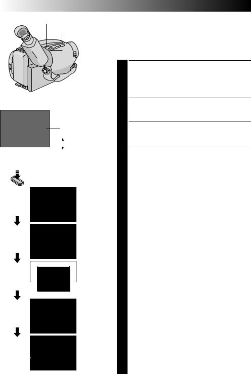
Tape Length Setting
Set the tape length according to the length of the tape used.
ACCESS MENU SCREEN
1 First set the System Select Switch to “VIDEO”, then set the Power Switch to “CAMERA”. Turn the Select Dial to any position except AUTO LOCK, then press the MENU Jog Dial.
SELECT FUNCTION
2 Rotate the MENU Jog Dial to move the highlight bar to “TAPE LENGTH”, then press it. The TAPE LENGTH Setting Menu appears.
SET TAPE LENGTH
3 Rotate the MENU Jog Dial to move the highlight bar to the correct setting. T20=20 minutes of recording time, T30=30 minutes, and T40=40 minutes (in SP).
•If you decide you want to return the tape length to the previous setting, rotate the MENU Jog Dial to move the highlight bar to “EXIT”.
CLOSE MENU
4 Press the MENU Jog Dial. The Menu Screen reappears and the highlight bar is on “MENU END”. Then press the MENU Jog Dial again to close the Menu Screen.
NOTES:
cThe tape remaining time (Z pg. 19) displayed in the viewfinder is correct only if the correct tape length has been selected.
cOnce you have set the tape length, it remains unchanged even if the Select Dial is returned to AUTO LOCK.
cWhen the System Select Switch is set to “D.S.C.”, it is not possible to set “REC TIME” and “TAPE LENGTH”.
4 
 2
2  3
3
1  5
5
|
Turn to take |
|
up slack. |
Erase Protection |
Gear |


 EN
EN 17
17

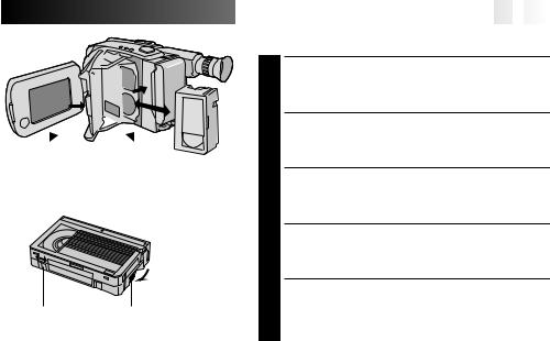
Loading/Unloading A Cassette
OPEN LCD MONITOR
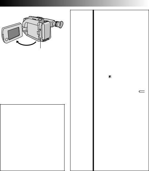
1 Open the LCD monitor to an angle of over 45 degrees.
OPEN CASSETTE HOLDER
2 Press EJECT until the holder opens. Do not use force to open.
INSERT/REMOVE CASSETTE
3 Make sure the label is facing outward.
CLOSE CASSETTE HOLDER
4 Press PUSH and make sure the holder is closed and locked.
CLOSE LCD MONITOR
5 First make sure the holder is closed. Then close the LCD monitor.
NOTES:
cClosing the LCD monitor while the cassette holder is still open may cause damage to the LCD monitor.
cA cassette holder can’t be opened unless a power supply is attached.
cMake sure that the tape is not slack when loading the cassette. If there is any slack, turn the gear on the cassette in the direction of the arrow to take up the slack.
cMake sure the Erase Protection tab is in the position that allows recording. If not, slide the tab. Some cassettes have removable tabs. If the tab has been removed, cover the hole with adhesive tape.
cThe cassette holder can’t be opened while the camcorder is in the record mode.

18

 EN
EN


 VIDEO
VIDEO


 RECORDING
 Basic
Basic
 Recording


LENS COVER Switch
Power indicator
Power
Switch
Start/Stop Button
System Select
Switch
Tally lamp
(lights while recording is in progress)
NOTE:
You should already have performed the procedures listed below. If not, do so before continuing.
cPower (Z pg. 10)
cRecording Mode/Tape Length Setting (Z pg. 16)
cGrip Adjustment (Z pg. 14)
LOAD A CASSETTE
1 First open the LCD monitor to an angle of over 45 degrees.
Press EJECT to open the cassette holder, then insert the cassette with the label facing out. Press PUSH to ensure the holder is closed and locked.
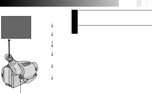
Shooting while watching the viewfinder
ENTER RECORD–STANDBY MODE
2 Make sure the LCD monitor is closed and locked. Slide the LENS COVER Open/Close Switch to open the lens cover. Set the System Select Switch to “VIDEO”, then set the Power Switch to “CAMERA”.
•The power indicator lights and the camcorder enters the Record–Standby mode.
•The scene you’re aimed at appears on the viewfinder screen, with the word “PAUSE” superimposed upon it.
START SHOOTING
3 Press the Recording Start/Stop Button.
•“REC ” appears in the viewfinder while recording is in progress.
Tape remaining time indicator
25MIN


 MIN
MIN
(Now calculating)
120MIN
119MIN
3MIN
2MIN
(Blinking)
1MIN
(Blinking)
0MIN
(Blinking)
Start/Stop Button


 EN
EN 19
19

STOP RECORDING
4 Press the Recording Start/Stop Button again to stop recording.
•The camcorder re-enters the Record-Standby mode.
NOTES:
cWhen the Power Switch is set to CAMERA and the LCD monitor is opened at an angle of 45 degrees or more, the LCD monitor switches on and the viewfinder switches off automatically to save power.
cA cassette holder can’t be opened unless a power supply is attached.
cThere may be a delay after you press EJECT until the holder opens. Do not use force.
cThe tape remaining time is only displayed in the viewfinder as shown.
cThe remaining time indicated in the viewfinder is approximate.
cThe time required to calculate the remaining tape length, and the accuracy of the calculation, may vary according to the type of tape used.
cThe tape remaining time indicator is correct only if the correct tape length has been selected (Z pg. 16).
c“TAPE END” appears when the tape reaches its end, and the power goes off automatically if left in this condition for 5 minutes. “TAPE END” also appears when a cassette whose tape is already at its end is loaded.
cIf the Record–Standby mode continues for 5 minutes without performing Zoom or any other operations, the camcorder’s power shuts off automatically. Set the Power Switch to “POWER OFF”, and then back to “CAMERA” to turn the camcorder on again.
cIf the Recording Start/Stop Button is pressed after the Record-Standby mode has continued for over
5 minutes, recording may not start immediately.
cIf you’re recording on a cassette from the middle (such
as when a tape is removed and re-inserted during recording), use the Retake function (Z pg. 23) to find the end of the last recording so you don’t erase any of it.
cThe LENS COVER warning blinks for about 5 seconds when the camcorder is turned on when the cover is closed.
cWhile shooting, sound is not heard from the speaker.
20

 EN
EN


 VIDEO
VIDEO


 RECORDING
 Basic
Basic
 Recording
 (cont.)


Shooting while watching the LCD monitor
180° |
90° |
Before the following steps, perform step 1 (Z pg. 18). |
LENS COVER Switch
Power indicator
Power
Switch
Start/Stop Button
ENTER RECORD–STANDBY MODE
2 Make sure the LCD monitor is fully open. Slide the LENS COVER Open/Close Switch to open the lens cover. Set the System Select Switch to “VIDEO”, then set the Power Switch to “CAMERA”.
•The power indicator lights and the camcorder enters the Record–Standby mode.
•The scene you’re aimed at appears in the LCD monitor, with the word “PAUSE” superimposed upon it.
START SHOOTING
3 Tilt the LCD monitor upward/downward for best viewability (Z pg. 21) and press the Recording Start/Stop button.
•“REC ” appears in the LCD monitor while recording is in progress.
STOP RECORDING
4 Press the Recording Start/Stop Button again to stop recording.
•The camcorder re-enters the Record-Standby mode.
|
|
|
|
|
|
|
|
Tally lamp |
System Select |
||
(lights while recording |
Switch |
||
is in progress) |
|
|
|
NOTES:
cWhen you use the LCD monitor outdoors in direct sunlight, the LCD monitor may be difficult to see. If this
happens, we recommend that you use the viewfinder (Z pg. 18).
cThe tape remaining time is not displayed on the LCD monitor. However, when the tape is about to reach its
end, the following indicators appear: “ 2MIN” ¥“ 1MIN” ¥“ 0MIN”.
cFor other notes, refer to pg. 19.


 EN
EN 21
21

Journalistic shooting
In some situations different angles of shooting may be required for more dramatic results.
OPEN LCD MONITOR
1 Make sure the LCD monitor is fully open.
TILT LCD MONITOR
2 Tilt the LCD monitor in the most convenient direction.
•The LCD monitor can rotate almost full circle (270°: 90° downward, 180° upward).
Interface shooting
A person you shoot can view himself/herself in the LCD monitor, and you can even shoot yourself while viewing your own image in the LCD monitor.
TILT LCD MONITOR UPWARD
1 Open the LCD monitor and tilt it upward to 180 degrees so that it faces forward.
•When the LCD monitor is tilted upward to an angle of over approx. 105 degrees, the monitor image is inverted vertically, and the viewfinder also switches on.
|
|
START RECORDING |
|
|
Point the lens toward the subject (yourself when |
Self-recording |
2 self-recording) and start recording. |
|
|
|
|
•During Interface Shooting, the monitor image and indications do not appear inverted as they would when viewing a mirror.
NOTE:
During Interface Shooting, indications other than the Date/Time display and Title display do not appear in the viewfinder.
|
Brightness control |
|
You can adjust the brightness of the LCD monitor by |
|
turning the BRIGHT Dial. |
|
ADJUST BRIGHTNESS |
|
If you want to brighten the image . . . |
|
1 Turn the Dial toward “+”. |
BRIGHT Dial |
If you want to darken the image . . . |
Turn the Dial toward “–”. |
22

 EN
EN


 VIDEO
VIDEO


 RECORDING
 Basic
Basic
 Features


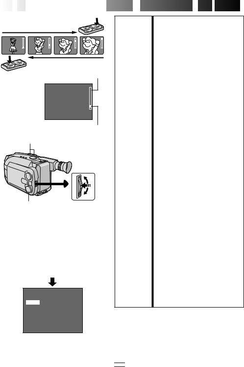
Zoom-in
Zoom-out
Zoom indicator bar
Zoom Level indicator Power Zoom button
Select Dial |
MENU Jog Dial |
|||||
LCD monitor or viewfinder |
||||||
|
|
|
|
|
|
|
|
|
MENU |
|
|
|
|
|
|
4MENU END |
AUTO |
|
||
|
|
FOCUS |
|
|||
|
|
EXPOSURE |
AUTO |
|
||
|
|
DATE TIME |
JAN 1. 98 |
|
||
|
|
TELE MACRO |
OFF |
|
||
|
|
TAPE LENGTH |
T30 |
|
||
|
|
M. W. B. |
AUTO |
|
||
|
|
ZOOM SPEED |
|
FAST |
|
|
|
|
4NEXT |
|
|
|
|
Menu Screen
ZOOM SPEED
FAST
SLOW
EXIT
ZOOM SPEED Setting Menu
FEATURE: |
Zooming |
PURPOSE: |
To produce the zoom in/out effect, or |
|
an instantaneous change in image |
|
magnification. |
|
Digital circuitly doubles the maximum |
|
22x magnification offered by optical |
|
zoom. This system is called Digital Zoom. |
OPERATION: |
Zoom In |
|
Press the “T” of the Power Zoom Button. |
|
Zoom Out |
|
Press “W” of the Power Zoom Button. |
|
n Zooming speed is available. A total of |
|
4 zoom speeds are available. 2 speeds |
|
can be selected depending on how |
|
hard the Power Zoom Button is |
|
pressed (press the button fully for |
|
regular-speed, press it lightly for slow- |
|
speed), while 2 speed levels (FAST/ |
|
SLOW) can be selected in the ZOOM |
|
SPEED Menu depending on the overall |
|
speed you prefer. |
|
The combinations of zoom speeds are |
|
shown in the chart below. |
Changing the ZOOM SPEED in the
Menu
1)Set the Select Dial to any position except AUTO LOCK and press the MENU Jog Dial. The Menu Screen appears.
2)Rotate the MENU Jog Dial to move the highlight bar to “ZOOM SPEED”, then press it. The ZOOM SPEED Setting Menu appears.
3)Rotate the MENU Jog Dial to move the highlight bar to the desired speed and press it twice. The Menu Screen disappears and setting is completed.
NOTES: c Focusing may become unstable during Zooming. In this case, set the zoom while in Record–Standby, lock the focus by using the manual focus (Z pg. 37), then zoom in or out in Record mode.
cThe zoom level indicator ( 5) moves during zoom. Once the zoom level indicator reaches the top of the zoom indicator bar, all magnification from that point is through digital processing.
cDuring Digital Zoom, the quality of image may suffer. To deactivate Digital
Zoom, set “D.ZOOM” to “OFF” in the Menu Screen (Z pg. 35).
Zooming Speed ( 1 – 4 in order of speed)
“ZOOM SPEED” |
Pressing the |
|
|
in the Menu |
Power Zoom Button |
||
Screen |
|
|
|
fully |
|
lightly |
|
|
|
||
|
|
|
|
FAST |
1 (fastest) |
|
3 |
SLOW |
2 |
|
4 (slowest) |
|
|
|
|

 : when the Select Dial is set to AUTO LOCK.
 P. STABILIZER
RETAKE (R/F)
|
|
|
|
EN |
|
23 |
|
|
|
|
|
|
|||
|
|
|
|
||||
|
FEATURE: |
Quick Review |
|||||
|
PURPOSE: |
To check the end of the last record- |
|||||
|
|
ing. |
|||||
|
OPERATION: |
1) Press “ ” and release quickly |
|||||
|
|
during the Record–Standby mode. |
|||||
|
|
n Tape is rewound for about 2 |
|||||
|
|
|
seconds and played back |
||||
|
|
|
automatically, then pauses in |
||||
|
|
|
Record–Standby mode for the |
||||
|
|
|
next shot. |
||||
|
NOTE: |
Distortion may occur at start of |
|||||
|
|
playback. This is normal. |
|||||
|
|
|
|
||||
|
FEATURE: |
Retake |
|||||
|
PURPOSE: |
To re-record certain segments. |
|||||
|
OPERATION: |
1) Make sure the camcorder is in the |
|||||
|
|
Record–Standby mode. |
|||||
|
|
2) Press either RETAKE button to |
|||||
|
|
reach the start point for new |
|||||
|
|
recording. Pressing “F” forwards |
|||||
|
|
the tape and pressing “R” reverses |
|||||
|
|
it. |
|||||
|
|
3) Press Recording Start/Stop Button |
|||||
|
|
to start recording. |
|||||
|
NOTE: |
Noise may appear during Retake. |
|||||
|
|
This is normal. |
|||||
|
|
|
|
||||
|
FEATURE: |
Picture Stabilizer |
|||||
|
PURPOSE: |
To compensate for unstable images |
|||||
|
|
caused by camera-shake, particularly |
|||||
|
|
at high magnification. |
|||||
|
OPERATION: |
1) Press P. STABILIZER. “ ”appears. |
|||||
|
|
n To switch off the Picture |
|||||
|
|
|
Stabilizer, press P. STABILIZER. |
||||
|
|
|
The indicator disappears. |
||||
NOTES: c Accurate stabilization may not be possible if hand shake is excessive, or under the following conditions:
•When shooting subjects with vertical or horizontal stripes.
•When shooting dark or dim subjects.
•When shooting subjects with excessive backlighting.
•When shooting scenes with movement in various directions.
•When shooting scenes with lowcontrast backgrounds.
cSwitch off the Picture Stabilizer when recording with the camcorder on a tripod.
24

 EN
EN


 VIDEO
VIDEO


 RECORDING


 Basic
Basic
 Features
 (cont.)


DATE/TIME
Display
Select Dial
Date display
Time display
Date/Time display
Auto Date Record mode
Date-off mode (No display)
Date display Auto Date Record mode
DEC 25.98 |
|
AUTO DATE |
|
|
|
Auto date record mode
Time display
PM10:50:00
Date/Time display
DEC 25.98
Auto date record executed
DEC 25.98 PM10:50:00
FEATURE: |
Date/Time Insert |
PURPOSE: |
To display the date and time on the |
|
LCD monitor, in the viewfinder, or |
|
on a connected color monitor, as |
|
well as to record them manually or |
|
automatically. |
OPERATION: |
1) Turn the Select Dial to any |
|
position except AUTO LOCK. |
|
2) Choose a display mode by |
|
pressing DATE/TIME repeatedly |
|
while in Record-Standby to cycle |
|
through the modes as shown in the |
|
illustration at left. |
|
n You should have already |
|
performed the Date/Time Setting |
|
procedure (Z pg. 13). If you |
|
haven’t, do so first. |
NOTES: DISPLAY
cThe selected display can be recorded.
cIf you don’t want to record the display, select the Date-off mode before shooting.
cIf you want to delete the display during shooting, press DATE/TIME.
cTo recall the display, engage the Record-Standby mode and press DATE/TIME repeatedly until the desired display appears.
cEven if you shoot with the date/ time displayed during Digital Still Camera Shooting, they will not be recorded.
AUTO DATE RECORD
cYour camcorder automatically records the date for about 5 seconds after recording is initiated in the following situations:
•After changing the date.
•After loading a cassette.
•After Auto Date Record mode is selected by pressing DATE/TIME.
In this mode, the date is replaced after 5 seconds with “AUTO DATE” but this is not recorded.
cSetting the Select Dial to AUTO LOCK always engages the Auto Date Record mode, and disables all other modes.
|
EN 25 |
|
FEATURE: |
Video Light |
|
PURPOSE: |
To brighten the scene when natural |
|
|
lighting is too dim. |
|
OPERATION: |
1) Set the LIGHT OFF/AUTO/ON |
|
|
Switch as required: |
|
|
ON : Always keeps the light on as |
|
|
long as the camcorder is |
|
|
turned on. |
|
|
AUTO : Automatically turns on the |
|
LIGHT OFF/AUTO/ON |
light when the camcorder |
|
senses insufficient lighting |
|
|
(Can be accessed when the |
on the subject. |
|
LCD monitor is opened) |
OFF : Turns off the light. |
|
|
n The video light can only be used |
|
|
with the camcorder’s power on. |
|
|
n It is recommended to set the white |
|
|
balance (Z pg. 39) to HALOGEN |
|
|
mode ( ) when you use the video |
|
|
light. |
|
|
n When not using the video light, |
|
|
turn it off to save battery power. |
|
NOTES: |
c Even if the battery indicator ( |
) |
|
does not blink if the battery pack’s |
|
|
charge is low, the camcorder may |
|
|
turn off automatically when you |
|
DANGER |
turn on the video light, or when |
|
you start recording with the video |
|
|
n The video light can become extremely |
light turned on. |
|
hot. Do not touch it either while in |
c When the LIGHT OFF/AUTO/ON |
|
operation or soon after turning it off, |
Switch is set to “AUTO”: |
|
otherwise serious injury may result. |
• Depending on the lighting |
|
n Do not place the camcorder into the |
conditions, the video light may |
|
carrying case immediately after using |
keep turning on and off. In this |
|
the video light, since it remains |
case, manually switch the light |
|
extremely hot for some time. |
on or off using the LIGHT OFF/ |
|
n When operating, keep a distance of |
AUTO/ON switch. |
|
about 30 cm. (1 ft.) between the video |
• While the Sports or High-Speed |
|
light and people or objects. |
Shutter mode (Z pg. 29) is |
|
n Do not use near flammable or explosive |
engaged, the light is likely to stay |
|
materials. |
on. |
|
n It is recommended that you consult your |
• While the Twilight mode |
|
nearest JVC dealer for replacing the |
(Z pg. 29) is engaged, the light |
|
video light. |
will not activate. |
|
26EN |
VIDEO RECORDING Basic Features |
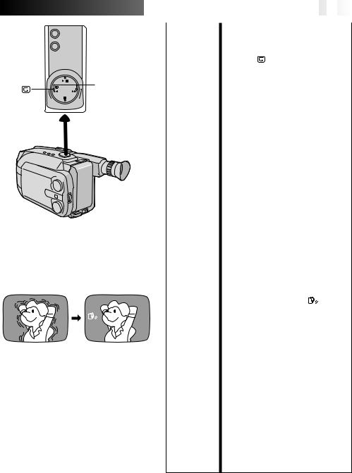
MODE |
Snapshot |
SNAPSHOT |
This interesting feature lets you record two types of |
|
digital still images that look like photographs onto a tape, |
|
as well as keeping them in the camcorder’s built-in |
|
memory. It is a great way to spice up footage of events |
|
such as parties, weddings and graduations. |
LCD monitor or viewfinder
P P
(Pin-Up)
SELECT SNAPSHOT MODE
1 Turn the Select Dial to any position except AUTO LOCK, then press the MODE Button to switch from one mode to the other as shown in the illustration to the left.
•When the Select Dial is set to AUTO LOCK, it is not possible to select the Snapshot Mode. Only the Full image (no display) is available. Go to step 2.
TAKE SNAPSHOT
2 Press the SNAPSHOT Button.
No display
(Full)
SNAPSHOT
LCD monitor or viewfinder (ex. Pin-Up)
1
 2
2
3
 4
4
 5
5
•A still image is recorded onto the tape and into the camcorder’s built-in memory.
•There are two Picture Modes you can choose from when storing in the camcorder’s memory: FINE and STANDARD. The maximum number of shots you can take varies according to the selected setting. The selected Picture Mode and remaining number of shots are displayed on the screen. The factory-preset is FINE. If you want to change the setting, perform “Picture Mode Setting” (Z pg. 49).
FINE
Allows you to shoot up to approx. 22 still images.
STD (Standard)
Allows you to shoot up to approx. 44 still images.
If you press during recording . . .
.... first there is a momentary camera shutter-type blackout together with the sound effect of a shutter closing, then a still image appears. The next image starts in the center of a black screen and wipes in toward the corners. The screen changes as shown in the illustrations 1 to 5 to the left and the screens 1 to 5 are recorded onto the tape in the selected mode. Only the still image 3 is stored in the built-in memory in the selected mode, then the camcorder resumes normal recording.
If you press during Record-Standby mode . . .
.... first there is a momentary camera shutter-type blackout together with the sound effect of a shutter closing, then a still image appears. The scene you are currently aimed at starts in the center of a black screen and wipes in toward the corners. The screen changes as shown in the illustrations 1 to 5 to the left. The screens 1 to 3 are recorded onto the tape in the selected mode. Only the still image 3 is stored in the built-in memory in the selected mode, then the camcorder re-enters the Record-Standby mode.

LCD monitor or viewfinder
FINE 12 Remaining number of shots
22  21
21  1
1 0
0
(Blinking)
Pictrue mode display:
FINE or STD (standard)
Pin-Up
A still image on a white background. A shadow effect is added to give it a three dimensional feel.
Full |
A still image that |
occupies the entire |
image field is recorded. |


 EN
EN 27
27

NOTES:
cSix sample images have been stored in the built-in memory at the factory.
If you wish to delete them, first remove the “Protect” function (Z pg. 59), then perform the “Delete” function (Z pg. 60).
cWhen the remaining number indicator displays “0” (blinking), the still image will be recorded onto the tape but not in the built-in memory. If you wish to store a still image in the built-in memory, perform the
“DELETE” function in the Menu Screen to remove still images you do not need (Z pg. 60).
cThe Picture Mode can be switched to either “FINE” or “STANDARD”. Since the remaining number of shots available depends on the selected Picture Mode, switching the Picture Mode will vary this number.
cIf the SNAPSHOT Button is pressed with the System Select Switch set to “D.S.C.”, the still image cannot be
recorded onto the tape, but will be stored in the camcorder's built-in memory (Z pg. 48).
cImage data stored in the camcorder’s built-in memory can be transferred to a Windows® PC or Macintosh®
and saved using the provided image transfer software (Z pg. 63). The image data transferred to a personal computer can also be further processed using Paint Software.
cWhen a Pin-Up is taken with the Wide mode (Z pg. 31) activated, the black bars at the top and bottom of the screen will disappear.
cWhen a Snapshot is taken in a dark environment, the still image recorded onto the tape and stored in memory will become coarse and its true colors will be lost.
28

 EN
EN


 VIDEO
VIDEO


 RECORDING

 Advanced
 Features


1 second later, the mode is activated.
After 1 sec.
 SEPIA
SEPIA
LCD monitor or viewfinder
Mark
|
|
LOCK |
R |
|
|
||
|
|
U |
|
|
|
||
|
0 |
A |
TO |
M |
E |
|
|
|
0 |
|
|
A |
|||
|
0 |
|
|
O S |
|||
2 |
|
|
|
D |
E |
||
/ |
|
|
|
|
E |
|
|
1 |
|
|
|
|
|
|
|
|
|
|
|
|
|
|
F |
|
|
|
|
|
|
|
G |
|
|
|
|
|
|
D |
N |
|
|
|
|
|
|
|
|
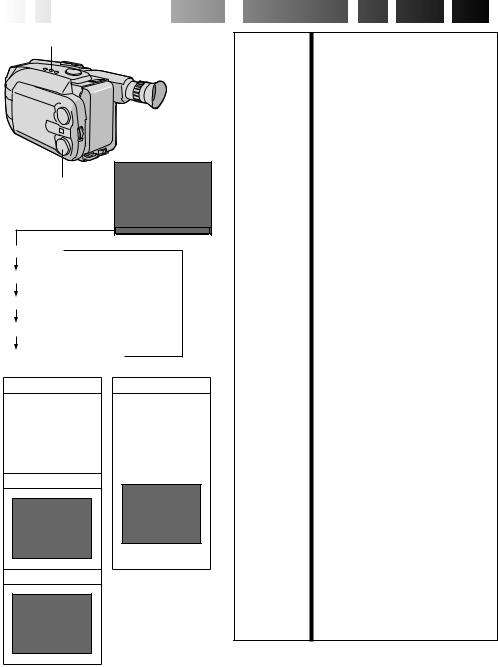
Program AE With Special Effects
All you have to do to access any of the variety of shooting effects is to turn the Select Dial.
SELECT MODE
1 Turn the Select Dial until the symbol of the function you want is aligned with the mark.
•The selected mode’s name and its indication are displayed for approx. 1 second. Then the name disappears, and only the indication remains. The mode is activated.
•When Auto Mode Lock or Auto Mode Release mode is selected, only the mode’s name is displayed. Then the name disappears and the mode is activated.
NOTES:
cOnly one effect can be engaged at a time.
cThe screen becomes slightly reddish when the Fade/ Wipe (Z pg. 30) is used in the Sepia mode.
cThe screen becomes slightly dark in the High Speed Shutter mode. Use in well-lit situations.
cIn the High Speed Shutter or Sports modes, picture color may be adversely affected if subject is lit by alternating discharge-type light sources such as flourescent or mercury-vapor lights.
Select Dial
 Loading...