


GR-AX227
GR-AX227
YU30052-523-1
GR-AX227
d in Japan
MKV
*
UN
*
YP
Compact VHS
INSTRUCTIONS
MANUAL DE INSTRUCCIONES
INSTRUÇÕES
COMP ACT VHS CAMCORDER
VIDEOCAMARA VHS COMPACTO
CÂMERA VHS COMPACT
ENGLISHESPAÑOLPORTUGUÊS
2
Dear Customer,
Thank you for purchasing the JVC Compact VHS
camcorder. Before use, please read the safety
information and precautions contained in the
following pages to ensure safe use of your new
camcorder.
Using This Instruction Manual
•All major sections and subsections are listed in the
Table Of Contents (Z pg. 7).
•Notes appear after most subsections. Be sure to
read these as well.
•Basic and advanced features/operation are
separated for easier reference.
It is recommended that you . . .
.... refer to the Index (Z pgs. 37 – 39) and
familiarize yourself with button locations, etc.
before use.
.... read thoroughly the Safety Precautions that
follow and cautions (Z pgs. 40, 41). They
contain extremely important information
regarding the safe use of your new camcorder.
SAFETY
PRECAUTIONS
WARNING:
TO PREVENT FIRE OR SHOCK
HAZARD, DO NOT EXPOSE
THIS UNIT TO RAIN OR
MOISTURE.
CAUTIONS:
n To prevent shock, do not open the cabinet.
No user serviceable parts inside. Refer
servicing to qualified personnel.
n When you are not using the AC Power
Adapter/Battery charger for a long period of
time, it is recommended that you disconnect
the power cord from AC outlet.
n Camcorder is designed exclusively for the
VHS-C video cassette. Only cassettes marked
VHS-C can be used with this unit.
n HQ VHS is compatible with existing VHS
equipment.
Warning on lithium battery
The battery used in this device may present a
fire or chemical burn hazard if mistreated. Do
not recharge, disassemble, heat above 100°C or
incinerate.
Replace battery with Panasonic (Matsushita
Electric), Sanyo or Maxell CR2025; use of
another battery may present a risk of fire or
explosion.
n Dispose of used battery promptly.
n Keep away from children.
n Do not disassemble and do not dispose of in
fire.
This camcorder is designed to be used with
NTSC-type colour television signals. It cannot
be used for playback with a television of a
different standard. However, live recording is
possible anywhere. Use the BN-V12U/V22U/
V25U battery packs and, to recharge them, the
provided multi-voltage AC Power Adapter/
Charger. (An appropriate conversion adapter
may be necessary to accommodate different
designs of AC outlets in different countries.)
NOTES:
●
The rating plate (serial number plate) and
safety caution are on the bottom and/or the
back of the main unit.
●
The rating plate (serial number plate) of the
AC Power Adapter/Charger is on its bottom.
This unit is produced to comply with Standard
IEC Publ. 65.
3
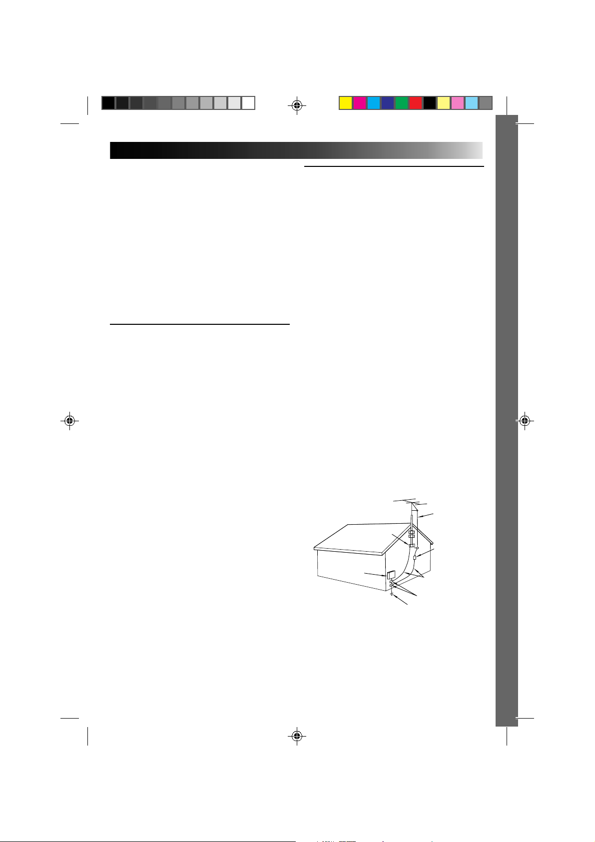
ANTENNA INSTALLATION
INSTRUCTIONS
1. Outdoor Antenna Grounding
If an outside antenna or cable system is connected
to the product, be sure the antenna or cable system
is grounded so as to provide some protection
against voltage surges and built-up static charges.
Article 810 of the National Electrical Code, ANSI/
NFPA 70, provides information with regard to
proper grounding of the mast and supporting
structure, grounding of the lead-in wire to an
antenna discharge unit, size of grounding conduc-
tors, location of antenna discharge unit, connection
to grounding electrodes, and requirements for the
grounding electrode.
2. Lightning
For added protection for this product during a
lightning storm, or when it is left unattended and
unused for long periods of time, unplug it from the
wall outlet and disconnect the antenna or cable
system. This will prevent damage to the product
due to lightning and power-line surges.
3. Power Lines
An outside antenna system should not be located in
the vicinity of overhead power lines or other
electric light or power circuits, or where it can fall
into such power lines or circuits. When installing an
outside antenna system, extreme care should be
taken to keep from touching such power lines or
circuits as contact with them might be fatal.
IMPORTANT PRODUCT
SAFETY INSTRUCTIONS
Electrical energy can perform many useful functions. But
improper use can result in potential electrical shock or fire
hazards. This product has been engineered and
manufactured to assure your personal safety. In order not to
defeat the built-in safeguards, observe the following basic
rules for its installation, use and servicing.
ATTENTION:
Follow and obey all warnings and instructions marked on
your product and its operating instructions. For your safety,
please read all the safety and operating instructions before
you operate this product and keep this manual for future
reference.
INSTALLATION
1. Power Sources
Operate your product only from the type of power
source indicated on the marking label. If you are
not sure of the type of power supply to your home,
consult your product dealer or local power
company. If your product is intended to operate
from battery power, or other sources, refer to the
operating instructions.
2. Overloading
Do not overload wall outlets, extension cords, or
integral convenience receptacles as this can result
in a risk of fire or electric shock.
3. Power Cord Protection
Power supply cords should be routed so that they
are not likely to be walked on or pinched by items
placed upon or against them, paying particular
attention to cords at plugs, convenience recepta-
cles, and the point where they exit from the
product.
4. Ventilation
Slots and openings in the cabinet are provided for
ventilation. To ensure reliable operation of the
product and to protect it from overheating, these
openings must not be blocked or covered.
•Do not block the openings by placing the product
on a bed, sofa, rug or other similar surface.
•Do not place the product in a built-in installation
such as a bookcase or rack unless proper
ventilation is provided or the manufacturer’s
instructions have been adhered to.
5. Wall or Ceiling Mounting
The product should be mounted to a wall or ceiling
only as recommended by the manufacturer.
ANTENNA
LEAD IN WIRE
ANTENNA
DISCHARGE UNIT
(NEC SECTION
810-20)
GROUNDING
CONDUCTORS
(NEC SECTION 810-21)
GROUND CLAMPS
POWER SERVICE GROUNDING ELECTRODE SYSTEM
(NEC ART 250. PART H)
NEC – NATIONAL ELECTRICAL CODE
ELECTRIC SERVICE
EQUIPMENT
EXAMPLE OF ANTENNA GROUNDING AS PER
NATIONAL ELECTRICAL CODE, ANSI/NFPA 70
GROUND CLAMP

4
USE
1. Accessories
To avoid personal injury:
• Do not place this product on an unstable cart, stand,
tripod, bracket or table. It may fall, causing serious injury
to a child or adult, and serious damage to the product.
• Use only with a cart, stand, tripod, bracket, or table
recommended by the manufacturer or sold with the
product.
• Use a mounting accessory recommended by the
manufacturer and follow the manufacturer’s instructions
for any mounting of the product.
• Do not try to roll a cart with small casters across
thresholds or deep-pile carpets.
2. Product and Cart Combination
A product and cart combination should be moved with
care. Quick stops, excessive force, and uneven surfaces
may cause the product and cart combination to overturn.
3. Water and Moisture
Do not use this product near
water—for example, near a bath
tub, wash bowl, kitchen sink or
laundry tub, in a wet basement, or
near a swimming pool and the
like.
4. Object and Liquid Entry
Never push objects of any kind into this product through
openings as they may touch dangerous voltage points or
short-out parts that could result in a fire or electric shock.
Never spill liquid of any kind on the product.
5. Attachments
Do not use attachments not recommended by the
manufacturer of this product as they may cause hazards.
6. Cleaning
Unplug this product from the wall outlet before cleaning.
Do not use liquid cleaners or aerosol cleaners. Use a damp
cloth for cleaning.
7. Heat
The product should be situated away from heat sources
such as radiators, heat registers, stoves, or other products
(including amplifiers) that produce heat.
SERVICING
1. Servicing
If your product is not operating correctly or exhibits a
marked change in performance and you are unable to
restore normal operation by following the detailed
procedure in its operating instructions, do not attempt to
service it yourself as opening or removing covers may
expose you to dangerous voltage or other hazards. Refer all
servicing to qualified service personnel.
2. Damage Requiring Service
Unplug this product from the wall outlet and refer servicing
to qualified service personnel under the following
conditions:
a. When the power supply cord or plug is damaged.
b. If liquid has been spilled, or objects have fallen into the
product.
c. If the product has been exposed to rain or water.
d. If the product does not operate normally by following
the operating instructions. Adjust only those controls that
are covered by the operating instructions as an improper
adjustment of other controls may result in damage and
will often require extensive work by a qualified
technician to restore the product to its normal operation.
e. If the product has been dropped or damaged in any way.
f. When the product exhibits a distinct change in
performance—this indicates a need for service.
3. Replacement Parts
When replacement parts are required, be sure the service
technician has used replacement parts specified by the
manufacturer or have the same characteristics as the
original part. Unauthorized substitutions may result in fire,
electric shock or other hazards.
4. Safety Check
Upon completion of any service or repairs to this product,
ask the service technician to perform safety checks to
determine that the product is in safe operating condition.
PORTABLE CART WARNING
(Symbol provided by RETAC)
5
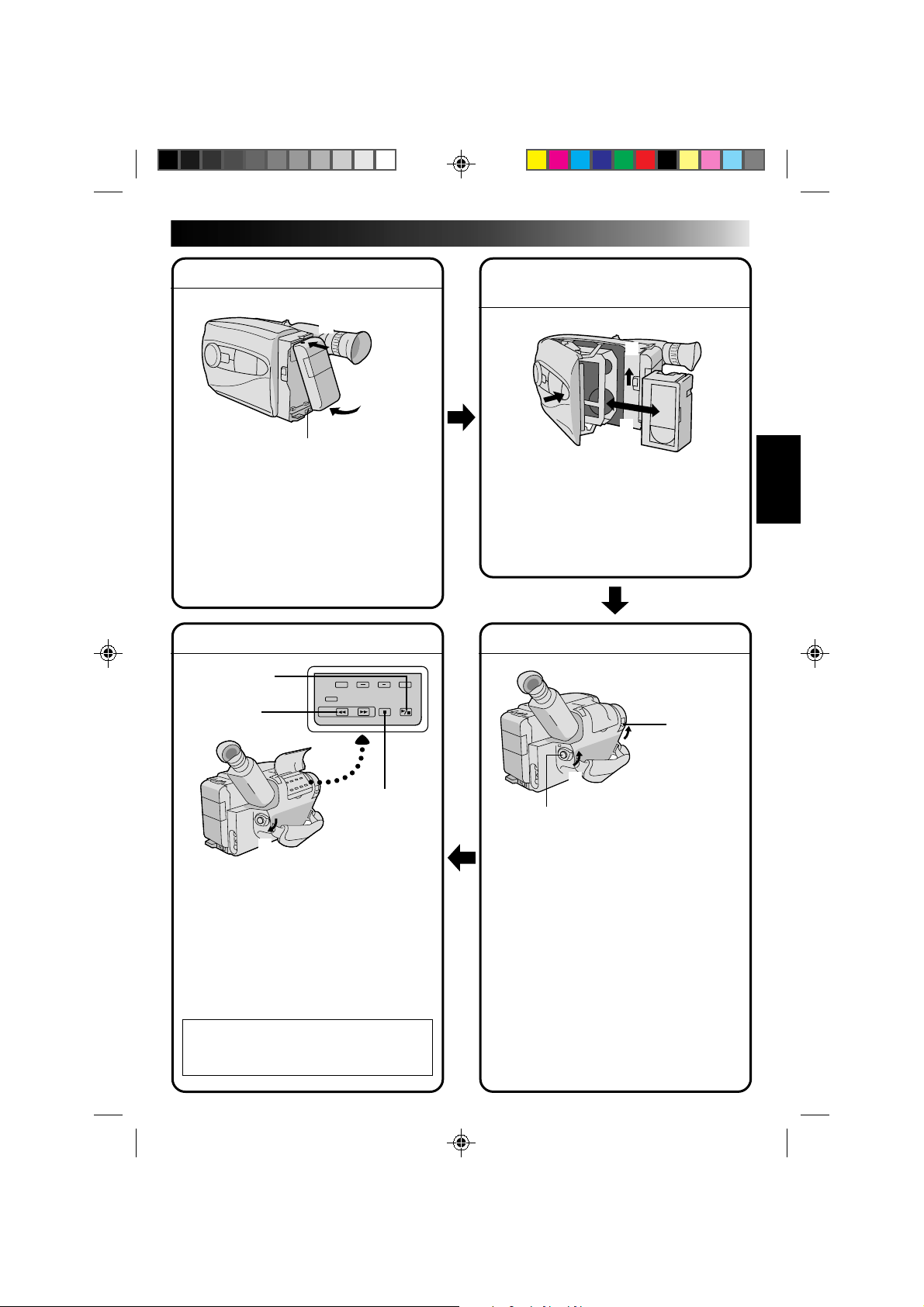
QUICK OPERATION GUIDE
SUPPLY POWER
Using the battery pack
1
Hook-on the battery pack's top end to the
camcorder. (Charging procedure, Z pg. 8)
2 Push in the battery pack until it locks into
place.
To remove the battery pack
Slide BATT. RELEASE and pull out the battery
pack.
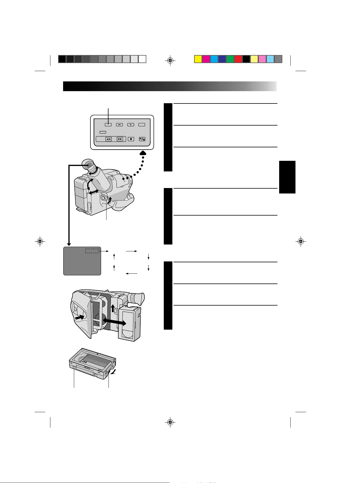
PLAYBACK
1 Set the power switch to “PLAY”.
2 Press REW.
— The tape will automatically stop at the
beginning of the tape.
3 Press PLAY/PAUSE.
— Playback starts and the playback picture
appears in the viewfinder.
•To stop playback, press STOP.
(For more details, Z pg. 30.)
n
Or simply play back the tape on a VHS
VCR using the Cassette Adapter
(VHS Playpak).
Z
pg. 28
SHOOTING
1 Slide the LENS COVER open/close knob to
open the lens cover.
2 Set the power switch to “CAMERA”.
— The power indicator will light and an
image will appear in the viewfinder.
3 Press the Recording Start/Stop button.
— Recording starts.
•To stop recording temporarily, momentarily
press the Recording Start/Stop button once
again.
(For more details, Z pg. 14)
2
Push in.
1
Hook on.
BATT. RELEASE
3
1
PUSH
Insert.
EJECT
2
2
REW
1
Set to “PLAY”.
1
LENS COVER
open/close knob
3
Recording Start/Stop button
2
Set to “CAMERA”.
INSERTING A VIDEO
CASSETTE
1 Slide EJECT.
2 Insert a video cassette.
3 Press PUSH.
(For more details, Z pg. 11)
STOP
3
PLAY/PAUSE
6
MAJOR FEATURES
REMEMBER
The Logical Choice
The only compact video
cassettes that can be
used with your VHS VCR*
*
with VHS Playpak
Program AE with Special
Effects (
Z P. 16)
n Auto Mode Lock
n Auto Mode Release
n Electronic Fog Filter
n ND Effect
n Sepia
n Twilight
n Sports
n High Speed (1/2000 sec.) Shutter
n 15 sec. Self Timer
Intelligent Function Control
(
Z P. 18 – 25)
SEL
F1
F2
Variable-Speed Hyper Zoom
(
Z P. 15)
PROVIDED ACCESSORIES
•AC Power Adapter/
Charger AA-V11EG
•Lithium Battery
•Shoulder Strap
•Battery Pack
BN-V12U
•Cassette Adapter
(VHS PlayPak)
C-P7U
Cassettes marked can be used with this camcorder.
T
W
T
W
T
W
T
W
Zoom-in
Zoom-out

7
CONTENTS
GETTING STARTED
8
Power.......................................................................................... 8
Clock (Lithium) Battery Removal/Insertion............................................. 10
Date/Time Settings ........................................................................ 10
Viewfinder Adjustment .................................................................... 11
Tape Length/Recording Mode Setting ................................................... 11
Loading/Unloading A Cassette ........................................................... 11
Grip Adjustment ............................................................................ 12
Shoulder Strap Attachment................................................................ 12
Tripod Mounting ............................................................................ 12
RM-V20U Remote Control Unit .......................................................... 13
RECORDING
14
Basic Recording ............................................................................. 14
Basic Features .............................................................................. 15
Advanced Features ......................................................................... 16
PLAYBACK
28
Using The Cassette Adapter............................................................... 28
Basic Connections........................................................................... 29
Basic Playback .............................................................................. 30
Features ..................................................................................... 31
EDITING
32
Tape Dubbing................................................................................ 32
Insert Editing................................................................................ 33
Audio Dubbing .............................................................................. 34
USER MAINTENANCE
35
TROUBLESHOOTING
36
INDEX
37
Controls...................................................................................... 37
Connectors................................................................................... 37
Indicators .................................................................................... 37
Other Parts.................................................................................. 37
Viewfinder .................................................................................. 38
Terms ......................................................................................... 39
CAUTIONS
40
SPECIFICATIONS
42
OPTIONAL ACCESSORIES
42
8
GETTING STARTED
Power
This camcorder’s 3-way power supply system lets you
choose the most appropriate source of power.
NOTES:
●
No function is available without power supply.
●
Use only specified power supply.
●
Do not use provided power supply units with other equipment.
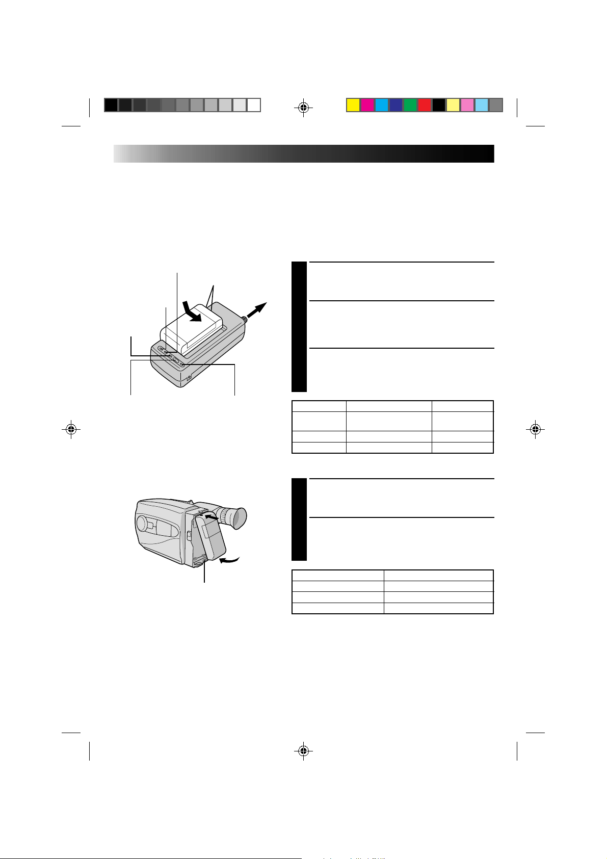
CHARGING THE BATTERY PACK
SUPPLY POWER
1
Connect the charger’s AC power cord to a wall
outlet. The power indicator lights.
ATTACH BATTERY PACK
2
Align the marks and slide the battery pack in the
direction of the arrow until it locks in place.
The CHG. indicator lights.
DETACH BATTERY PACK
3
When charging is completed, the END indicator
lights. Slide the battery pack opposite the direction
of the arrow.
USING THE BATTERY PACK
ATTACH BATTERY PACK
1
Hook its top end to the camcorder and push the
battery pack in until it locks in place.
DETACH BATTERY PACK
2
Slide BATT. RELEASE and pull out the battery pack.
**REFRESH
The AC power adapter features a REFRESH function that
allows you to fully discharge the battery pack before
recharging.
To discharge the battery . . .
.... attach the battery pack to the adapter as shown in the
illustration to the left. Then push REFRESH. The
REFRESH indicator lights when discharging starts,
and goes out when discharging is complete.
BATT. PACK RECORDING TIME
BN-V12U approx. 1 hr. 5 min.
BN-V22U approx. 2 hrs. 15 min.
BN-V25U approx. 3 hrs.
BATT. PACK CHARGE DISCHARGE
BN-V12U approx. 1 hr. 10 min.
approx.
3 hrs. 30 min.
BN-V22U approx. 2 hrs. 10 min. approx. 7 hrs.
BN-V25U approx. 2 hrs. 40 min. approx. 10 hrs.
REFRESH indicatorREFRESH switch
CHG. (charge) indicator
To AC outlet
Marks
END
indicator
Hook on.
Push in.
BATT. RELEASE
POWER
indicator
9
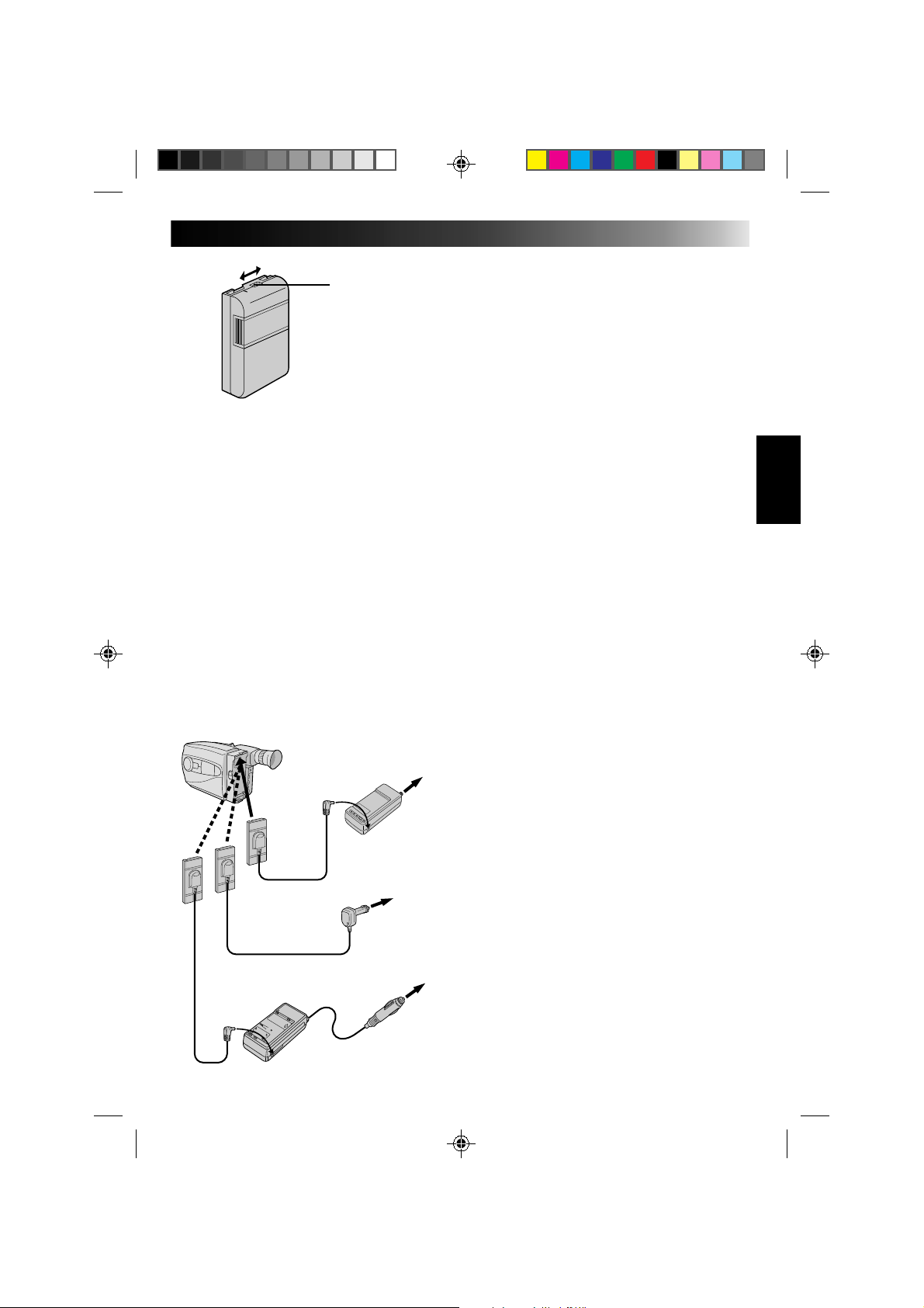
**CHARGE MARKER
A charge marker is provided on the battery pack to
help you remember whether it has been charged or
not. Two colors are provided (red and black)—you
choose which one means charged and which
means discharged.
NOTES:
●
The recording time per charge is affected by such factors as the time spent in Record/Standby mode and
the frequency of zooming. It is safer to have spare battery packs.
●
Charging times noted on page 8 are for fully discharged battey pack, and discharging times are for fully
charged battery pack.
●
Charging and discharging times vary according to the ambient temperature and the status of the battery
pack.
●
Remember to set the charge marker after charging a battery pack or after detaching a discharged one from
your camcorder.
●
Perform the REFRESH function after no less than 5 chargings.
●
High temperatures can damage the battery pack, so use only where good ventilation is available. Don’t
allow it to discharge in container, such as a bag.
●
If you stop recharging or discharging part way through, make sure to remove the battery pack before
unplugging the adapter’s AC cord.
●
Remove the battery pack from the adapter immediately after discharging.
●
To avoid interference with reception, do not use the AC Power Adapter/Charger near a radio.
●
Make sure you unplug the DC cord before charging or discharging the battery pack.
●
A blinking CHG. indicator means that the battery pack has become hot. Wait until it cools down to
continue.
●
The CHG. indicator may not light properly with a brand new battery pack, or with one that’s been stored
for an extended period. In this case, remove and reattach the battery pack and recharge it. The CHG.
indicator should light during recharging. If not, contact your nearest JVC dealer.
USING A CAR BATTERY
Use the optional Car Battery Cord or Car Battery
Charger/Adapter (connect as shown in the
illustration to the left).
NOTES:
●
When using the car battery, leave the engine
idling.
●
The optional Car Battery Charger (BH-V3U) can
also be used to charge the battery pack.
●
When using the optional Car Battery Charger or
Car Battery Cord (AP-V7U), refer to the respective
instruction booklet.
USING AC POWER
Use the AC Power Adapter (connect as shown in
the illustration to the left).
NOTE:
The supplied AC Power Adapter/Charger features
automatic voltage selection in the AC range from
110 V to 240 V.
Charge marker
DC OUT terminal
To AC outlet
AC Power
Adapter/Charger
AA-V11EG
DC cord
Car Battery Cord
AP-V7U (optional)
To car’s
cigarette
lighter
socket
Car Battery Charger/Adapter
BH-V3U (optional)
10
DATE JAN 1.00
TIME AM12:00
A
GETTING STARTED (cont.)
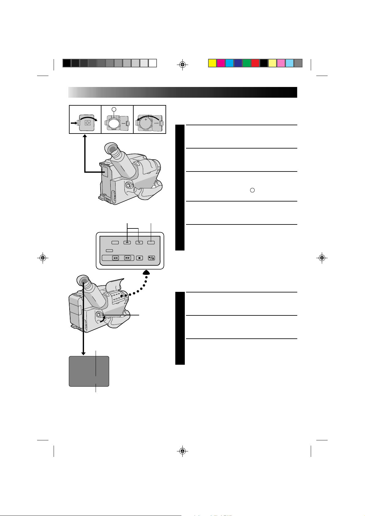
Clock (Lithium) Battery Removal/Insertion
This battery is necessary for clock operation and to
perform date/time settings.
SWITCH OFF POWER
1
Switch off the unit’s power and remove the power
supply unit.
OPEN COVER
2
Open the clock battery compartment cover while
pressing the release tab.
REMOVE BATTERY (when replacing)
3
Insert a pointed, non-metallic object between the
battery and the compartment (
A
) and pull the
battery out.
INSERT BATTERY
4
Ensuring the plus (+) side is up, insert the supplied
lithium battery and push it in.
CLOSE COVER
5
Close the compartment cover until it clicks in place.
NOTE:
See “SAFETY PRECAUTIONS”(
Z
pg. 2) for information
on safe handling of lithium batteries.
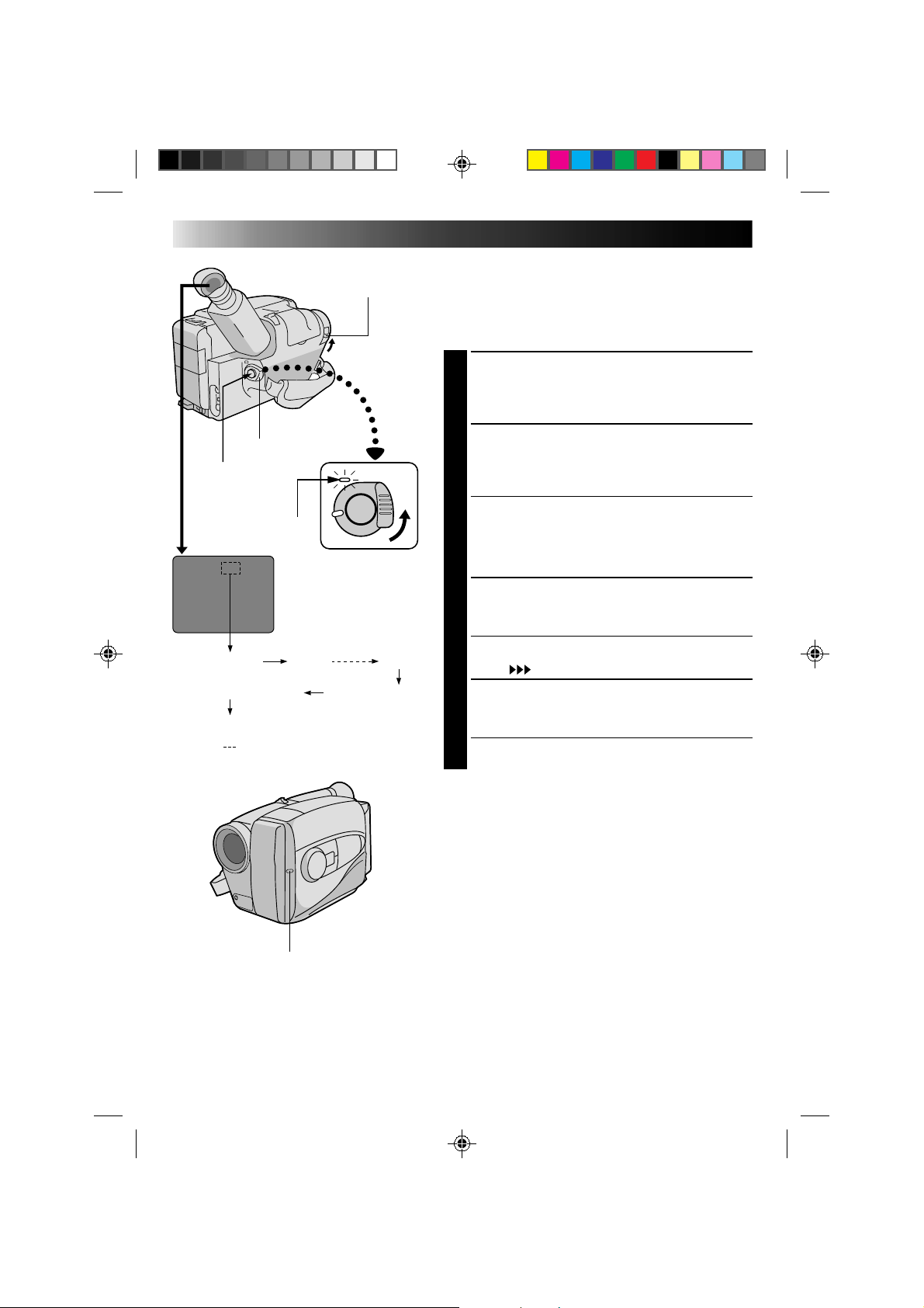
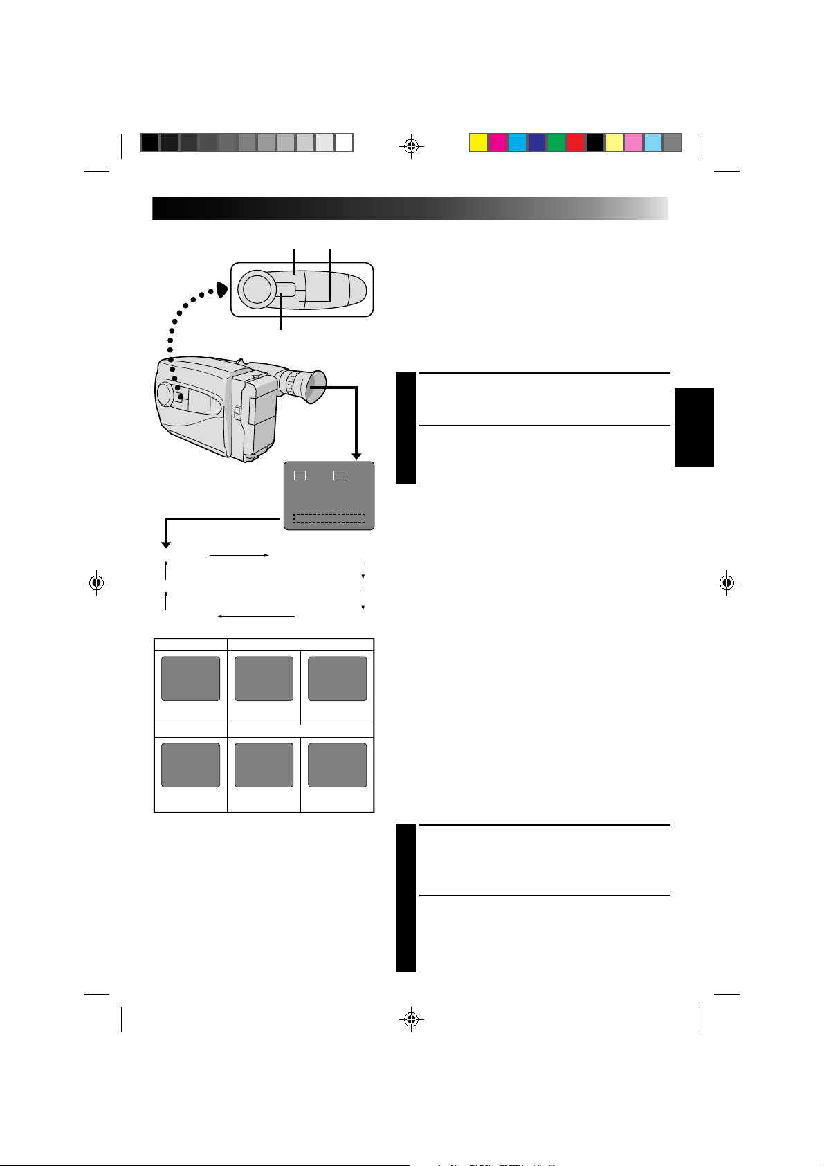
Date/Time Settings
SELECT MODE
1
Set the power switch to CAMERA.
SET DATE/TIME
2
Press SET and the month blinks. Press + or – to set
the month. Repeat to set day, year, hour and minute.
START CLOCK
3
Press SET. The blinking stops. The date and time are
both displayed for confirmation, then the time
display disappears.
NOTE:
The clock does not keep time while the date and time are
blinking.
–/+ SET
POWER
Time
12-hour indication with AM or PM
TIME .... Time setting is performed
Date
Month/Day/Year
DATE ... Date setting is performed
11
T30 SP
T20 SP
T40 EP
T20 EP
T30 SP
T40 SP T30 EP
Viewfinder Adjustment
POSITION VIEWFINDER
1
Adjust the viewfinder manually for best viewability
(see illustration at left).
SELECT MODE
2
Set the power switch to CAMERA.
ADJUST DIOPTER
3
Turn the diopter adjustment control until the
indications in the viewfinder are clearly focused.
Tape Length/Recording Mode Setting
SET TAPE LENGTH
1
Set the tape length button according to the length of
the tape used. T20 = 20 minutes of recording time,
T30 = 30 minutes, and T40 = 40 minutes (in SP).
SET RECORDING MODE
2
Set depending on your preference. “SP” (Standard
Play) provides higher picture and sound quality and
is better for dubbing, while “EP” (Extended Play) is
more economical, recording at 1/3 the speed of SP.
Loading/Unloading A Cassette
OPEN CASSETTE HOLDER
1
Slide EJECT until the holder opens. Do not use force
to open.
INSERT/REMOVE CASSETTE
2
Make sure the label is facing outward.
CLOSE CASSETTE HOLDER
3
Press PUSH and make sure the holder is closed and
locked.
NOTES:
●
A cassette holder can’t be opened unless a power
supply is attached.
●
Make sure that the tape is not slack when loading the
cassette. If there is any slack, turn the gear on the
cassette in the direction of the arrow to take up the
slack.
●
Make sure the Erase Protection tab is present. If not,
cover the hole with adhesive tape. (Some cassettes
have sliding tabs – in this case, check the tab's
position.)
Set POWER to “CAMERA”.
SP-EP recording mode and
T20•30•40 tape length select button
GearErase Protection
Turn to take up
slack.
Tape length and recording
mode indicator
12
2
3
1
2
1
GETTING STARTED (cont.)
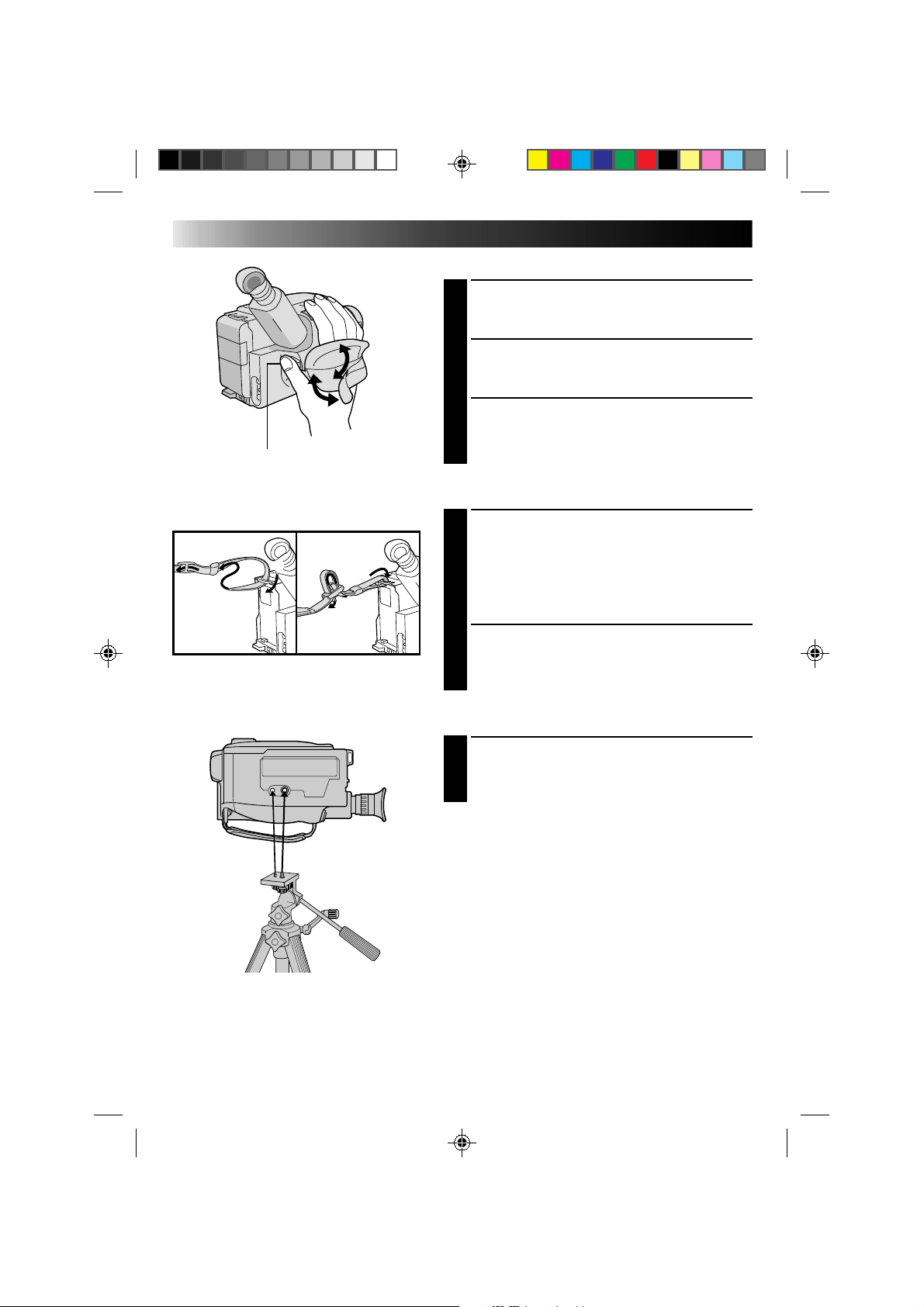
Grip Adjustment
EXPAND LOOP
1
Separate the Velcro strip.
INSERT HAND
2
Pass your right hand through the loop and grasp the
grip.
ADJUST STRAP LENGTH
3
Adjust so your thumb and fingers can easily operate
the Recording Start/Stop button and Power Zoom
switch. Refasten the Velcro strip.
Shoulder Strap Attachment
ATTACH STRAP
1
Following the illustration at left, thread the strap
through the top of the eyelet 1, then fold it back
and thread it through the keeper 2, and then
through the buckle 3. Repeat the procedure to
attach the other end of the strap to the other eyelet,
making sure the strap isn’t twisted.
ADJUST LENGTH
2
Adjust as shown in the illustration at left 1, then
slide both keepers snug against the eyelets to
prevent slipping 2.
Tripod Mounting
ALIGN AND TIGHTEN
1
Align the screw and camera direction stud on the
tripod with the camera’s mounting socket and stud
hole. Then tighten the screw.
Recording Start/Stop button
13
1
2
4
3
5
6
7
8
9
0
!
@
#
$
%
^
&
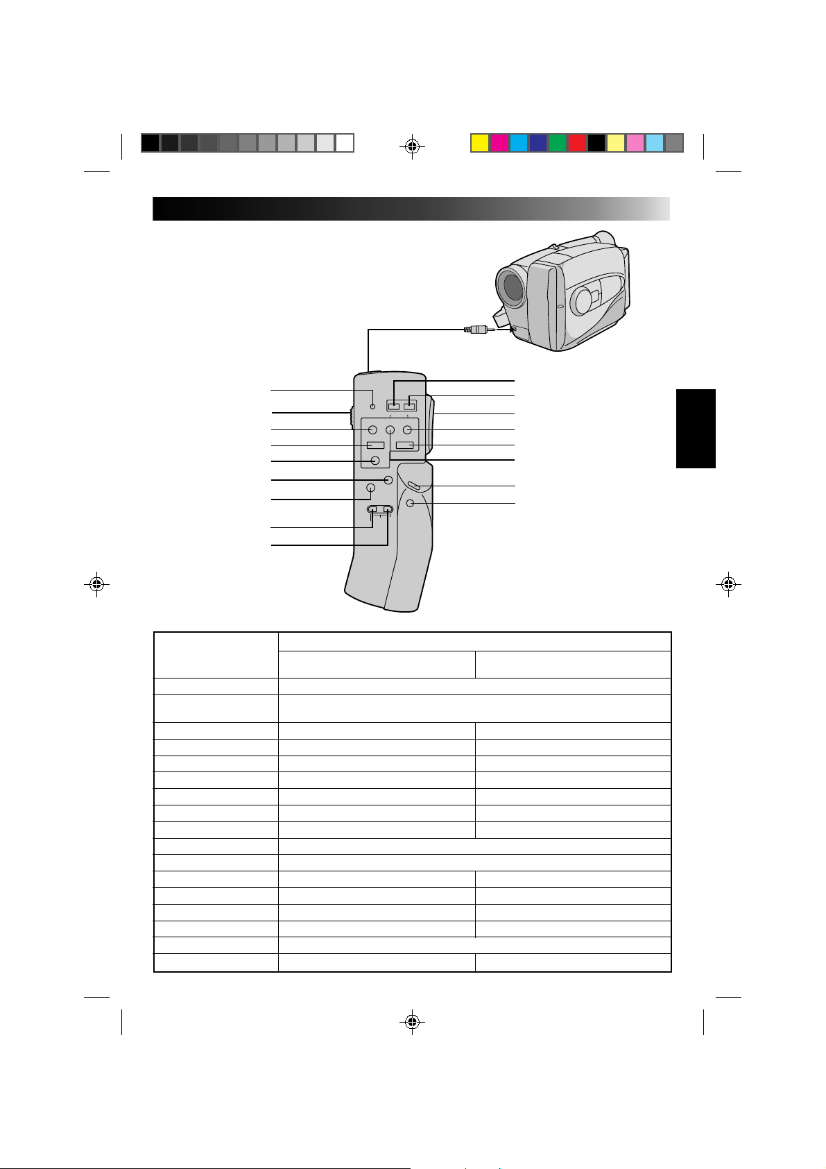
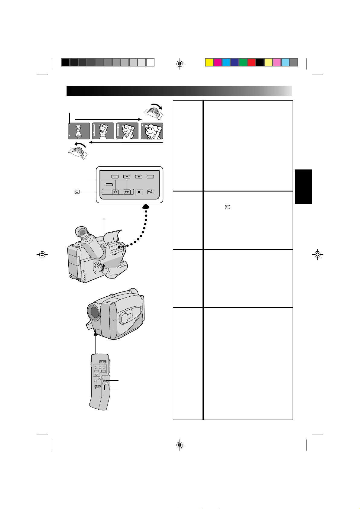
RM-V20U Remote Control Unit
The RM-V20U (optional) permits VCR functions to
be controlled from a distance. When using the
RM-V20U, connect its cable to the camcorder's
REMOTE jack.
* Before use, refer to the RM-V20U instruction
booklet.
To REMOTE
Buttons
Functions
With the camcorder’s power switch With the camcorder’s power switch set
set to “CAMERA”. to “PLAY”.
1 LED indicator Lights when a signal is transmitted.
2 KEY-LOCK switch
Switching to “;” turns off the remote control unit‘s power. Decreases battery power
consumption, and prevents accidental operation by young children, etc.
3 REC ——
4STOP — Stop (Z pg. 30)
5 PAUSE/MONITOR — Pause (Z pg. 31)
6 AUDIO DUB — Audio Dubbing (Z pg. 34)
7 INSERT — Insert Editing (Z pg. 33)
8 REC TIME Animation/Time-Lapse (Z pg. 27) —
9 INTERVAL Self-Timer (Z pg. 26)/Time-Lapse (Z pg. 27) —
0 POWER OFF Power off
! POWER ON Power on
@ ZOOM (T/W) Slow-speed zoom (Z pg. 15) —
# FF/RETAKE Retake (Forward) (Z pg. 15) FF/FF Shuttle Search (Z pg. 30)
$ PLAY — Playback start (Z pg. 30)
% REW/RETAKE Retake (Rewind) (Z pg. 15) Rew/Rew Shuttle Search (Z pg. 30)
^ START/STOP Functins same as the Recording/Stop button of a camcorder.
& VISS Index Code Marking (Z pg. 15) —
14
120MIN 119MIN
3MIN
2MIN (Blinking)
1MIN (Blinking)
0MIN (Blinking)
* MIN.....(Now calculating)
RECORDING
Basic Recording
NOTE:
You should already have performed the procedures listed
below. If not, do so before continuing.
●
Power (
Z
pg. 8)
●
Tape Length/Recording Mode Setting (
Z
pg. 11)
●
Grip Adjustment (
Z
pg. 12)
LOAD A CASSETTE
1
Slide EJECT to open the cassette holder, then insert
the cassette with the label facing out. Press PUSH to
ensure the holder is closed and locked.
ENTER RECORD–STANDBY MODE
2
Slide the LENS COVER open/close switch to open
the lens cover, then set the power switch to
CAMERA.
•The power indicator lights and the camcorder
enters the Record–Standby Mode.
•The scene you’re aimed at appears on the
viewfinder screen, with the word “PAUSE”
superimposed upon it.
START SHOOTING
3
Press the Recording Start/Stop button.
•The tally lamp lights while recording is in progress,
and “
REC
” appears in the viewfinder.
STOP RECORDING
4
Press the Recording Start/Stop button again to stop
recording.
•The camcorder re-enters the Record-Standby
mode.
NOTES:
●
A cassette holder can’t be opened unless a power
supply is attached.
●
There may be a delay after you slide EJECT until the
holder opens. Do not use force.
●
The tape’s remaining time is displayed in the
viewfinder as shown.
●
“TAPE END” appears when the tape reaches its end,
and the power goes off automatically if left in this
condition for 5 minutes. “TAPE END” also appears
when a cassette whose tape is already at its end is
loaded.
●
If the Record–Standby mode continues for 5 minutes,
the camcorder’s power shuts off automatically. Set the
power switch to POWER OFF, and then back to
CAMERA to turn the camcorder on again.
●
If you’re recording on a cassette from the middle, use
the RETAKE function (
Z
pg. 15) to find the end of the
last recording so you don’t erase any of it.
●
The LENS COVER warning blinks for about 5 seconds
when the camcorder is turned on, whether the cover is
open or closed.
LENS COVER
SWITCH
POWER
Tally lamp
The power indicator
Start/Stop
Tape remaining time
indicator
15
T
W
T
W
T
W
T
W
RETAKE
Power zoom switch
RM-V20U (optional)
START/STOP
VISS
Zoom-in
Zoom indicator
Zoom-out
RECORDING
Basic Features
FEATURE: Zooming
PURPOSE: Varies the focal length of the lens and
produces the zoom in/out effect.
OPERATION:
Zoom In
1) Pull the power zoom switch down
toward “T”.
Zoom Out
2) Push the switch up toward “W”.
NOTES: ●
The further the power zoom switch is
pushed, the faster the zoom speed
becomes.
●
Focusing may become unstable during
zooming. In this case, set the zoom while
in Record–Standby, set manual focus or
Focus Lock (
Z
pg. 20, 21), then zoom in
or out in Record mode.
FEATURE: Quick Review
PURPOSE: To check the end of the last recording.
OPERATION: 1) Press “
” for less than 2 seconds during
the Record–Standby mode.
• Tape is rewound for about 2 seconds
and played back automatically, then
pauses in Record–Standby mode for the
next shot.
NOTE:
Distortion may occur at start of playback.
This is normal.
FEATURE: Retake
PURPOSE: To re-record certain segments.
OPERATION: 1) Make sure the camcorder is in the
Record–Standby mode.
2) Press either RETAKE button to reach the
start point for new recording.
3) Press Recording Start/Stop to start
recording.
NOTE:
Noise may appear during Retake.
This is normal.
FEATURE: Index Code Marking
PURPOSE: To give you automatic access to any selected
point on a recording. Auto Marking and
Manual Marking are available.
OPERATION:
Auto Marking
An index code is always marked to start the
first recording on a new date after a cassette
is inserted.
Manual Marking (Using the optional
RM-V20U Remote Control Unit)
1) Press VISS once to place the index code.
INDEX blinks in the viewfinder during
marking.
NOTES: ●
If VISS is pressed during
Record–Standby mode, the mark is
placed where START/STOP is pressed.
●
If the date changes during a recording, it
becomes the first recording of the new
date and an index mark is placed at that
point.
16
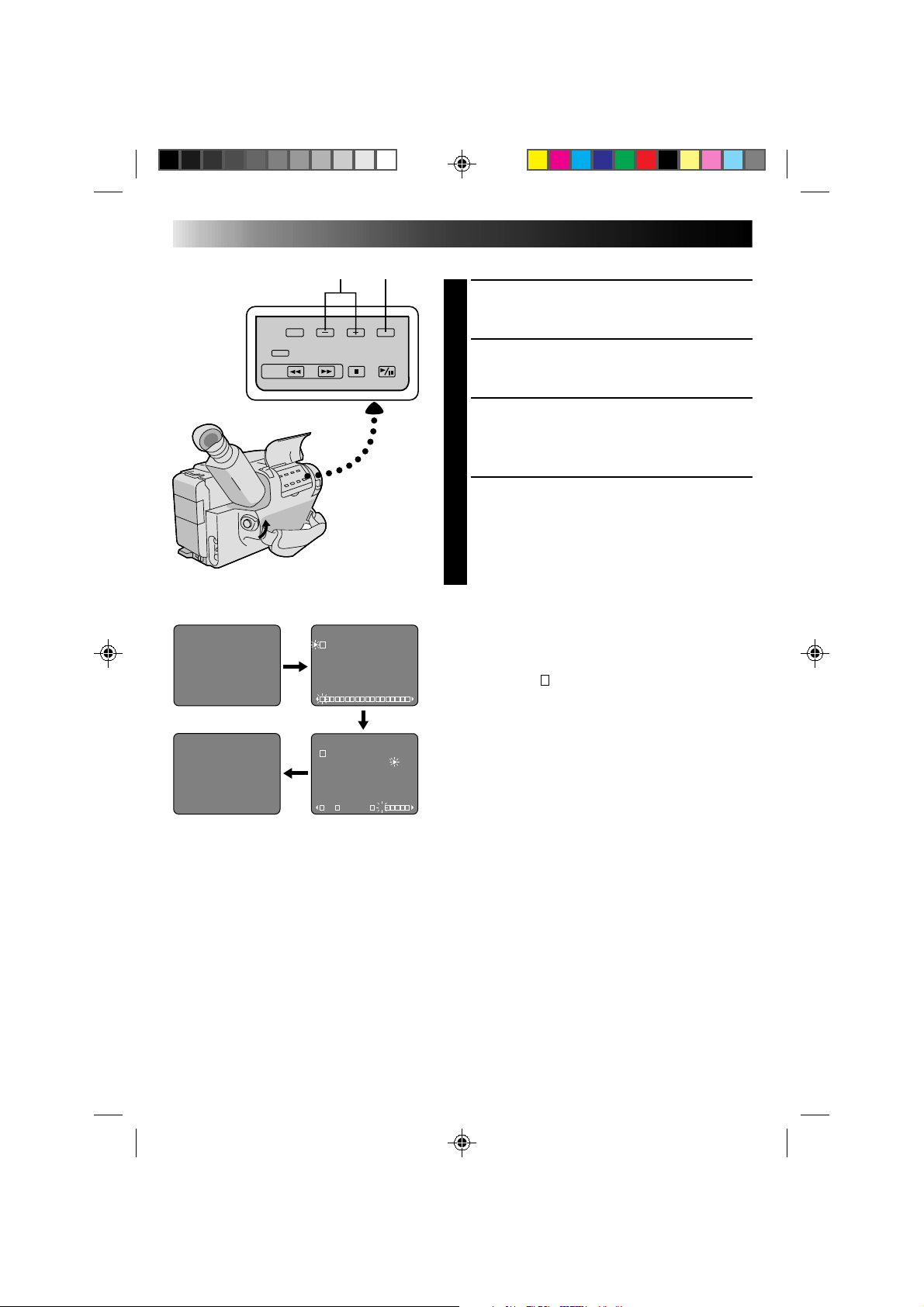
DIAL VIEWFINDER
MODE
SYMBOL INDICATION
Sports
High shutter speed clearly captures fast-moving
action.
High-Speed Shutter (1/2000s.)
Captures faster action than Sports mode.
15sec. Self-Timer
Lets you delay recording start after Recording Start/
Stop is pressed. If camcorder is secured, operator
can enter scene before recording starts.
1) Set PROGRAM AE dial to “
”. “ 15S” appears
in viewfinder.
2) Press Recording Start/Stop.
•Recording starts after 15 seconds.
•Tally lamp begins blinking; blinking speed
increases about 5 seconds before recording starts.
Blinking stops when recording begins but light
stays on.
NOTES:
●
Only one effect can be engaged at a time.
●
When the PROGRAM AE select dial is switched
from one mode to another, the newly selected
mode's name and its indication is displayed in the
viewfinder for approx. 3 seconds. Then the name
disappears, and only the indication remains.
●
The screen becomes slightly reddish when the
fader (
Z
pg. 18) is used in the Sepia mode.
●
The screen becomes slightly dark in the High
Speed Shutter mode. Use in well-lighted
situations.
●
In the High Speed Shutter or Sports modes,
picture color may be adversely affected if subject
is lit by alternating discharge-type light sources
such as flourescent or mercury-vapor lights.
RECORDING
Advanced Features
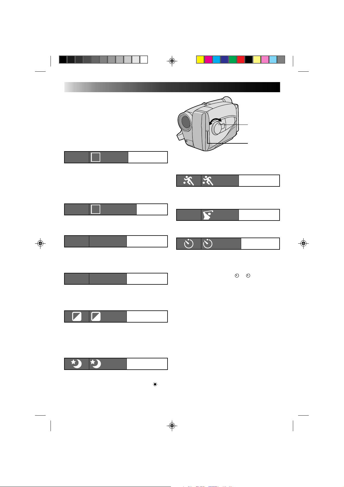
Sports
SPORTS
15 sec. Self-Timer
SELF TIMER
Program AE With Special Effects
All you have to do to access any of the variety of
shooting effects is to turn the PROGRAM AE select
dial until the desired indication appears in the
viewfinder. The mode is activated about 1 second
later.
PROGRAM AE
select dial
Tally lamp
High Speed Shutter
1/2000
S 1/2000
DIAL VIEWFINDER
MODE
SYMBOL INDICATION
Auto Mode Lock
Locks the camcorder in Full Auto mode, preventing
incorrect operation due to accidental button
pressing during shooting.
•CINEMA, FADER, FOCUS, EXPOSURE, DISPLAY,
TITLES and MWB (Manual White Balance)
controls are disabled in this mode.
Auto Mode Release
Re-enables the controls that were disabled by Auto
Mode Lock.
Electronic Fog Filter
Makes the picture look misty white, as when an
external fog filter is attached to the lens. Softens the
image and gives it a “fancy“ look.
ND EFFECT
A black mist darkens the picture, as when an ND
filter is used. Helps to counter the effects of glare on
the subject.
Sepia
The scene being shot is recorded in sepia-tinted
(reddish-brown) monochrome, giving the effect of
an older movie. Use together with Cinema
(
Z pg. 19) for the authentic look of a classic
Hollywood movie.
Twilight
Disengages the auto gain control and auto focus,
locks focus to infinity and white balance to “ ”
(outdoor) mode. Dusk, twilight scenery, fireworks,
etc., look more natural and dramatic.
A
Auto Mode Lock
LOCK
AUTO LOCK
Auto Mode
Release
RELEASE
AUTO RELEASE
M
Electronic Fog Filter
FG:FOGFG
ND EffectND:ND EFFECTND
Sepia
SEPIA
Twilight
TWILIGHT
17
No indication
(Auto)
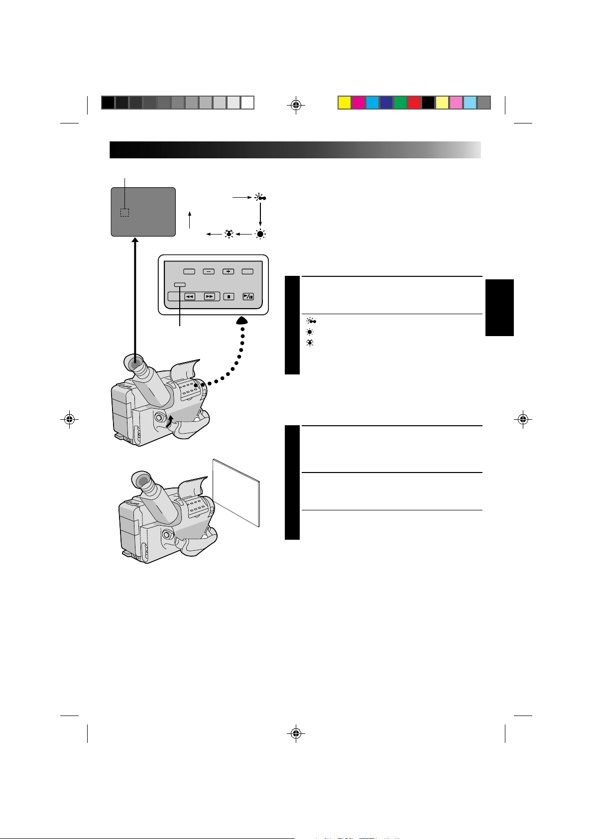
MWB
White balance mode indicator
MWB
White Balance Adjustment
This camcorder’s Automatic Color Temperature system
senses the color temperature of the ambient lighting for
automatic white balance adjustment. However, precise
color adjustment is not possible under the following
conditions:
•When an object is in various shades of the same color.
•When a predominantly red or brown object is being
shot outdoors.
In these cases, use the camcorder’s built-in preset filters
for white balance adjustment.
SELECT MODE
1
Press MWB (Manual White Balance) until the
required indication appears in the viewfinder.
“ ” .............. Outdoors on cloudy day
“
” ............... Outdoors on sunny day
“ ” ................ Light source is halogen or tungsten
...................... lamp
“MWB” .......... With a memorized personal White
...................... Balance setting (see below)
MWB sets the color temperature for the subject’s light
source so you can shoot with natural colors that are
unaffected by surroundings, even when there are
multiple subjects with different color temperatures.
ADJUST FOCUS
1
Point the camcorder at a white, flat object such as a
sheet of white paper, and adjust focus manually
(Z pg. 21).
ADJUST WHITE BALANCE
2
Press MWB until ”MWB“ appears, then press and
hold MWB for more than 3 seconds.
•”MWB” blinks in the viewfinder during
adjustment, then stops blinking but stays lit when
adjustment is complete.
NOTES:
●
To switch to automatic white balance adjustment, press MWB until the indication disappears, or turn the
PROGRAM AE dial to LOCK.
●
Re-adjust the White Balance mode when the lighting has changed, when the camcorder has been turned
on and off again, or when the PROGRAM AE dial’s position has been changed.
●
It is helpful to connect your camcorder to a color monitor when adjusting the white balance
(“BASIC CONNECTIONS”
Z
pg. 29).
●
When adjusted by putting colored paper in front of the subject in step 2 , this unit makes its color
temperature standard for automatic white balance. So you can enjoy shooting with different colors. For
example, when adjusting with red, blue or yellow colors, the image becomes the color which aproximates
to green, orange or purple respectively.
18
SEL
F1
F2
FADER CINEMA
FADER CINEMA
FOCUS
EXP.
TITLE
DISP.
Group 1
Group 2
Group 3
SEL.
SEL.
SEL.
F1 F2
F1
F2
F2
F1
F1
F2
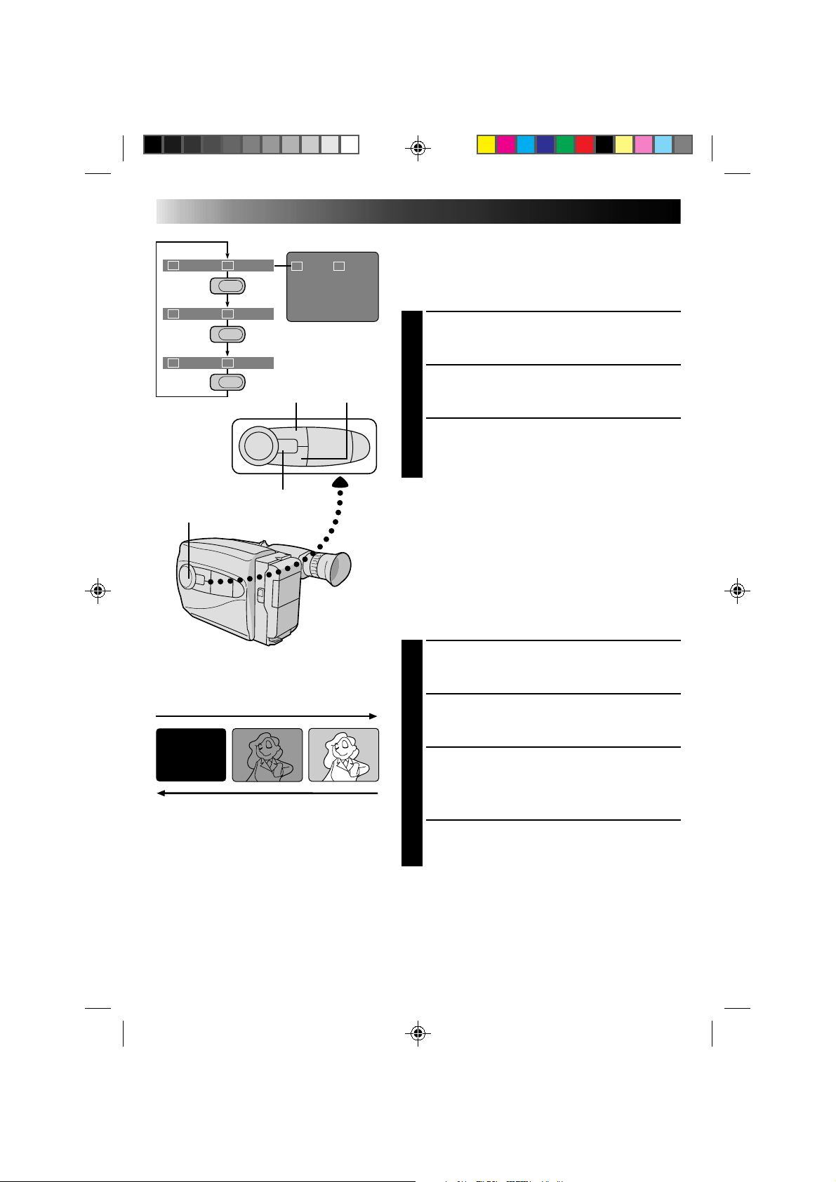
RECORDING
Advanced Features
INTELLIGENT FUNCTION CONTROL
This feature makes it easier for you to make selections
during the following modes: Fader, Cinema, Manual
Focus Adjust, Exposure Control, Display, and Instant
Title.
PREPARATION
1
Set the PROGRAM AE dial to any position except
LOCK.
SELECT MODE
2
Press Function SEL. repeatedly until the required
function’s indication appears in the viewfinder.
ENTER SELECTION
3
Press either F1 or F2 (the one to the immediate left
of the desired function name).
NOTE:
If you set the PROGRAM AE dial to LOCK, F1 and F2
disappear from the viewfinder, indicating that IFC
(Intelligent Function Control) is unavailable.
Fader
This feature allows smooth fade-in and fade-out to black
blank screen. Fade-in works at recording start, and
fade-out works at recording end or when you enter
Record–Standby mode.
SELECT MODE
1
Press Function SEL. repeatedly until “FADER”
appears to the right of F1.
ENGAGE FADE–STANDBY MODE
2
Press F1 to engage the Fade–Standby mode.
“FADER”appears in the viewfinder.
START RECORDING
3
Press Recording Start/Stop to start recording and
activate fade-in.
OR . . .
END RECORDING
Press Recording Start/Stop to end recording and
engage fade-out.
NOTES:
●
Pressing and holding the Recording Start/Stop button
allows you to record a black blank screen.
●
The screen becomes slightly reddish when the Fader is
used with Sepia (
Z
pg. 16).
●
With the Electronic fog filter mode (
Z
pg. 16)
engaged, the image fades in/out to a white screen.
Viewfinder
F2 buttonF1 button
PROGRAM AE select dial
Function SEL. button
FADE IN
FADE OUT
19
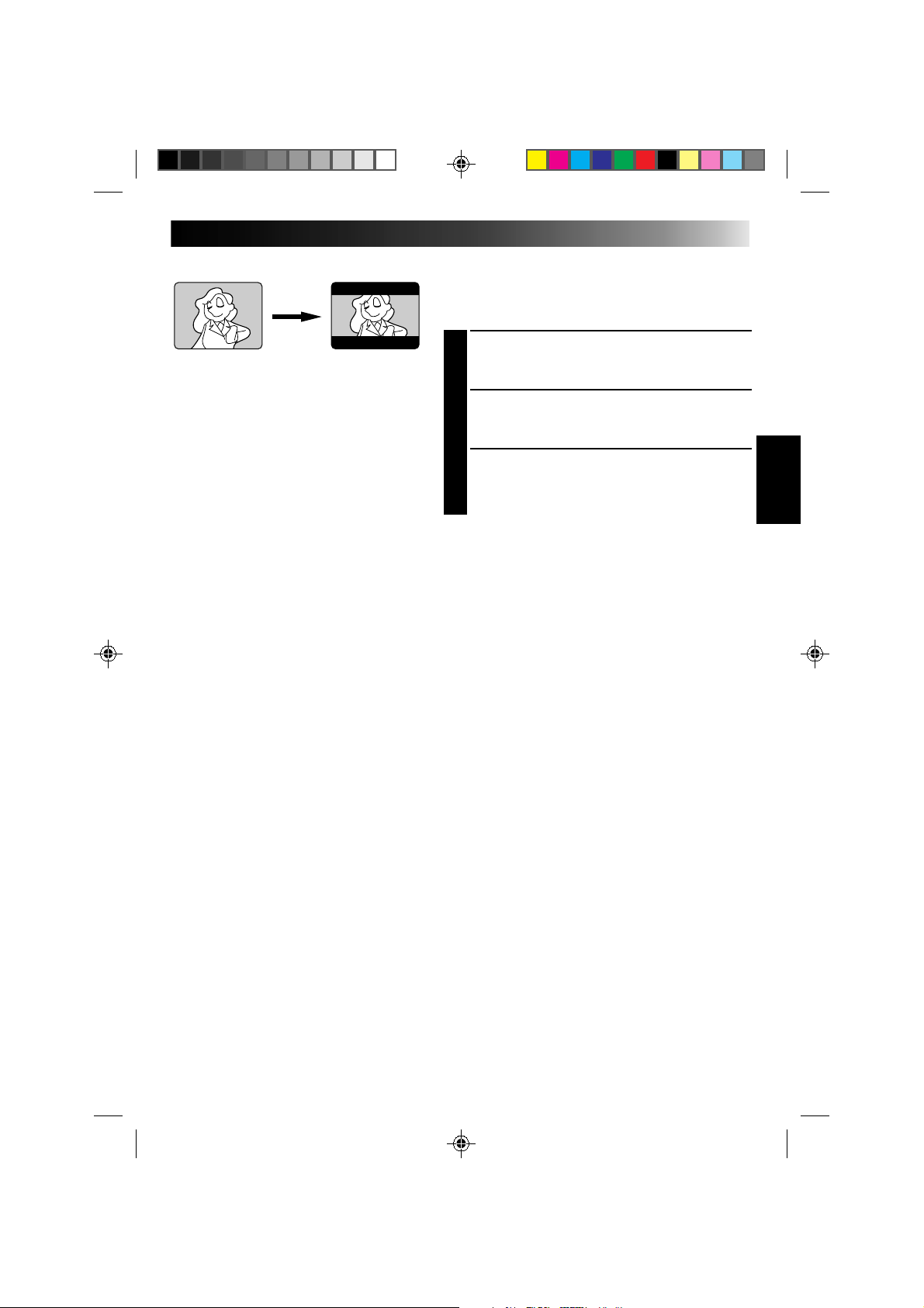
Cinema
This feature allows you to record black bars at the top
and bottom of the screen to produce a cinema-like
“wide-screen” effect.
SELECT MODE
1
Press Function SEL. repeatedly until “CINEMA”
appears to the right of F2.
ENGAGE CINEMA MODE
2
Press F2.
RESTORE NORMAL SCREEN
3
Press F2 again while “CINEMA” appears next to F2
in the viewfinder.
Cinema mode
20
RECORDING
Advanced Features
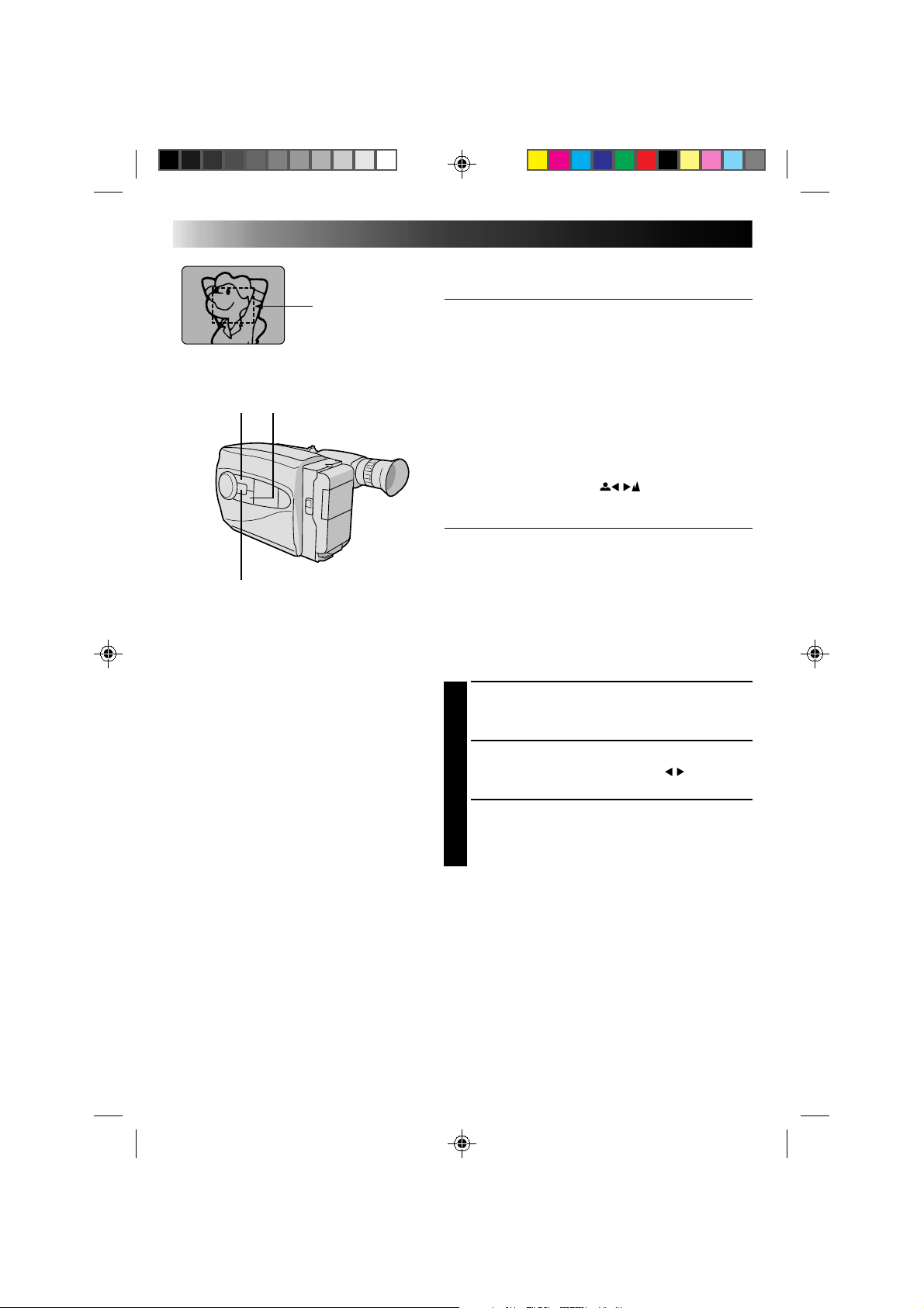
Focus
detection zone
Focusing
Auto Focus
The camcorder’s Full Range AF system offers continuous
shooting ability from close-up to infinity. However,
correct focus may not be obtainable in the situations
listed below (in these cases use manual focusing):
•When two subjects overlap in the same scene.
•When illumination is low.*
•When the subject has no contrast (difference in
brightness and darkness), such as a flat, one-color wall,
or a clear, blue sky.*
•When a dark object is barely visible in the viewfinder.*
•When the scene contains minute patterns or identical
patterns that are regularly repeated.
* The low-contrast warning “
” appears in the
viewfinder.
Focus Lock
This feature locks the focus in place, which is especially
helpful in the following situations:
•When things pass between your subject and the
camcorder. Engage the focus lock function to lock your
subject in before recording.
•When you want your subject to be focused, and to
appear in a corner of the screen. First, center on the
subject and focus using auto focus mode. Then engage
the focus lock function and move the camcorder until
the subject is where you want it.
SELECT MODE
1
Press Function SEL. repeatedly until “FOCUS”
appears to the right of F1.
LOCK FOCUS
2
Press F1. The focus lock indication “ ” appears
in the viewfinder.
RELEASE FOCUS LOCK
3
Press F1. Focus lock is immediately released. The
focus lock indication disappears.
NOTES:
●
If the lens is smeared or blurred, accurate focusing is
not possible. Keep the lens clean, wiping with a piece
of soft cloth if it gets dirty. When condensation occurs,
wipe with a soft cloth or wait for it to dry naturally.
●
When shooting a subject close to the lens, zoom-out
first (
Z
pg. 15). If zoomed-in in the auto focus mode,
the camcorder could automatically zoom out
depending on the distance between the camcorder and
the subject.
F1 F2
Function SEL.
21
SEL
F1
F2
FOCUS EXP.
F1
F2
F1
+
F1
+
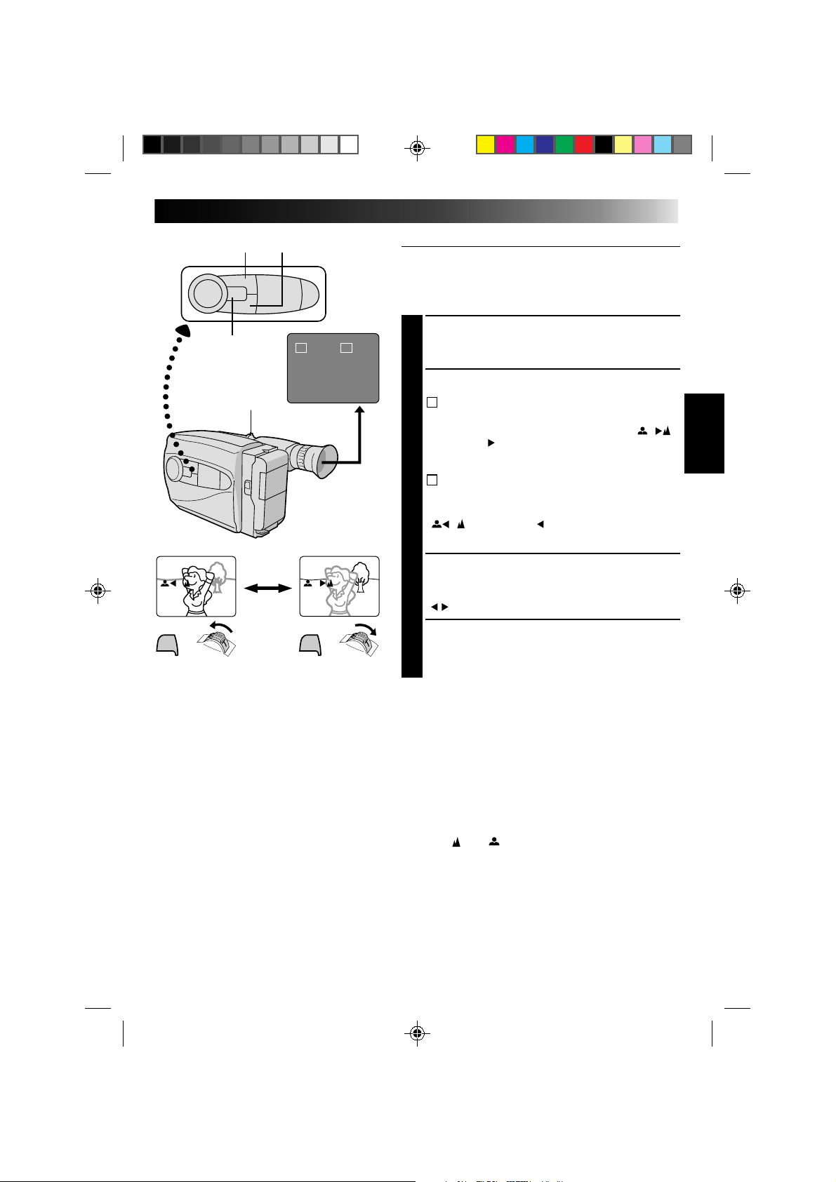
Manual Focus
NOTE:
You should already have made the necessary viewfinder
adjustments (
Z
pg. 11). If you haven’t, do so before
continuing.
SELECT MODE
1
Press Function SEL. repeatedly until “FOCUS”
appears to the right of F1.
ADJUST FOCUS
2
A
TO FARTHER SUBJECT
2
While holding down F1, slide the power zoom
switch to T. The Manual Focus indications “ ”
appear and “ ” blinks.
Go to step 3.
B
TO NEARER SUBJECT
While holding down F1, slide the power zoom
switch to W. The Manual Focus indications
“
” appear and “ ” blinks.
Go to step 3.
LOCK FOCUS
3
Release the power zoom switch. The focus
indication is replaced by the focus lock indication
“ ” and the adjusted focus is locked in.
RELEASE MANUAL FOCUS MODE
4
Press F1. The Manual Focus mode is immediately
released and the focus lock indication disappears.
NOTES:
●
Be sure to focus the lens in the maximum telephoto
position when you use the Manual Focus mode. If you
focus in on a certain subject in the wide-angle position,
sharply focused images cannot be obtained when
zoomed up because the depth-of-field is reduced at
longer focal lengths.
●
Two manual focusing speeds are available. For
slow-speed, push the switch slightly and hold that
position. For fast-speed, push the switch fully.
●
When the focus level cannot be adjusted any farther or
closer, “ ” or “ ” will blink.
F1 button F2 button
Function SEL.
button
Power zoom switch
Viewfinder
22
SEL
F1
F2
FOCUS EXP.
F1
F2
+
-
+
-
+
-
+
F2
+
F2
RECORDING
Advanced Features
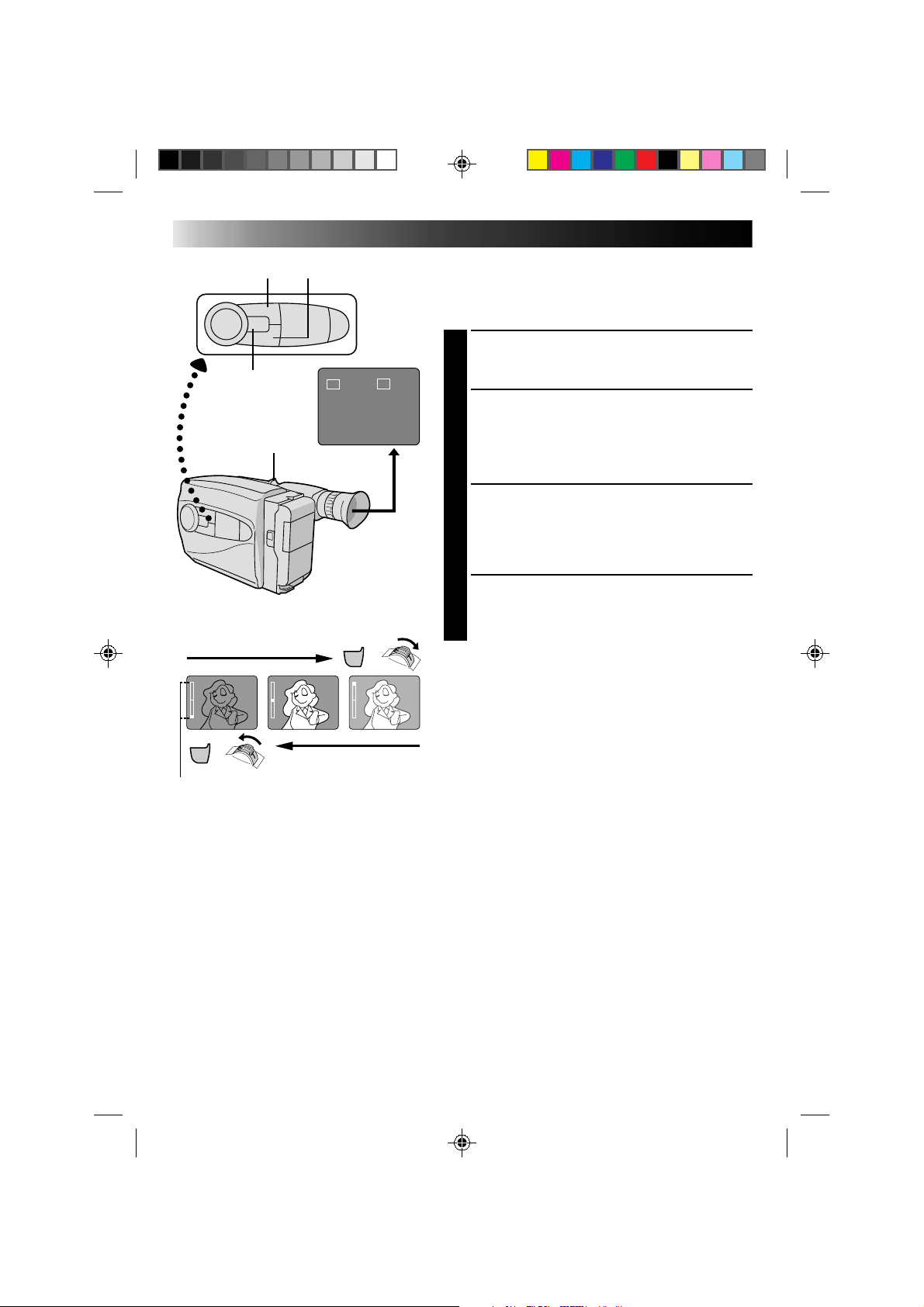
Exposure Control
This feature automatically adjusts the iris for the best
available picture quality, but you can override and make
the adjustment manually.
SELECT MODE
1
Press Function SEL. repeatedly until “EXP.” appears
to the right of F2.
BRIGHTEN IMAGE
2
While holding down F2, slide the power zoom
switch to T. The Exposure indicator bar appears in
the viewfinder.
OR . . .
DARKEN IMAGE
While holding down F2, slide the power zoom
switch to W. The Exposure indicator bar appears in
the viewfinder.
When you want to return to the factory setting . . .
RESTORE INITIAL SETTING
3
Press F2. The standard setting is immediately
restored and the Exposure indicator bar disappears.
F1 button F2 button
Function SEL.
button
Power zoom switch
Viewfinder
Exposure indicator bar
To brighten the image
To darken the image
23
NOTES:
●
In the On-Screen Display mode, the date is
displayed and recorded.
●
The on-screen display is not available during
recording.
Date/Time Character Insert
This feature allows you to display date, time and characters
in your viewfinder and on a connected color monitor,
record them manually or automatically, and even make
your own titles.
NOTE:
You should already have performed the Date/Time Setting
procedure (
Z
pg. 10). If you haven’t, do so before continuing.
DISPLAY
SELECT DISPLAY
1
Press Function SEL. repeatedly until “DISP.” appears
to the right of F2.
CHOOSE DISPLAY MODE
2
Press F2 while in Record–Standby to cycle through
the modes as shown in the illustration at left.
NOTES:
●
The selected display can be recorded.
●
If you don’t want to record the display, select Date-off mode
before shooting.
●
If you want to delete the display during shooting, press F2.
●
If you want to call back a deleted display, engage the Record–
Standby mode and then select the desired display mode using F2.
AUTO DATE RECORD
Your camcorder automatically records the month, day
and year for about 5 seconds after recording is initiated
in the following situations:
•After changing the date.
•After loading a cassette.
•After Auto Date Record mode is selected by pressing
F2. In this mode, the month, day and year are replaced
after 5 seconds with “AUTO DATE”.
NOTES:
●
Setting PROGRAM AE to LOCK always engages this mode, and
disables all other modes.
●
In the Auto Date Record mode, if the date changes while you’re
shooting, the date indication is recorded for about 5 seconds
from that point. It is not recorded during any other recordings
made on that day.
ON-SCREEN DISPLAY
CONNECT CAMCORDER TO
MONITOR
1
Connect the camcorder to a monitor as instructed in
“BASIC CONNECTIONS” (Z pg. 29).
DISPLAY VIEWFINDER
INDICATIONS
2
Press F2 until the indications appear on the
connected monitor.
Date display
Auto Date Record mode
Date/Time display
Date-off mode
On-screen display
Character Generator
DEC 25.96
DEC 25.96
AUTO DATE
Date display
Auto Date Record mode
Date/Time display
Character Generator
Auto date
record mode
Auto date
record executed
No Characters
stored
Example of
stored characters
IN PARIS, FRANCE
DEC 25.96 PM 10:50
SET CHAR
TITLE DISP.
F1 F2
SEL
F1
F2
F2 button
Function SEL. button
F1 button
24
SET CHAR
IN PARIS, FRANCE
CHARACTER SET MODE
J K L M N O P Q R S
T U V W X Y Z Ä Ö Ü
À È Ì Ò Ù Ñ Æ Ø Å &
: . , ' - / ! ? ¿ k
0 1 2 3 4 5 6 7 8 9
A B C D E F G H I
CHARACTER SET MODE
J K L M N O P Q R S
T U V W X Y Z Ä Ö Ü
À È Ì Ò Ù Ñ Æ Ø Å &
: . , ' - / ! ? ¿ k
0 1 2 3 4 5 6 7 8 9
A B C D E F G H I
I N PAR I S, FR
RECORDING
Advanced Features
Character Generator
SELECT MODE
1
Press Function SEL. repeatedly until “DISP.” appears
to the right of F2.
SET CHARACTER OR TITLE
2
Press F2 until “SET CHAR” or a previously stored
title appears in the viewfinder.
ACCESS CHARACTER MODE
SCREEN
3
Press SET. A character grid appears in the view
finder.
ENTER DESIRED CHARACTERS
4
Press + or – to move the cursor on the character grid
to the desired character, then press SET to enter. The
selected characters appears at the bottom of the
screen. When you’re done, press SET as many times
as necessary to exit the screen. The title you made
appears at the bottom of the screen.
NOTES:
●
You can store up to 18 characters.
●
You can only make and store one title at a time. To
replace it, repeat the procedure.
●
To create a space between two characters in a title you
make, choose “
” on the CHARACTER SET MODE
screen.
SET–/+
CHARACTER
SET MODE screen
CHARACTER
SET MODE screen

25
Example of Character Generator & Title
Viewfinder
Character Generator:
IN PARIS, FRANCE
Title indication
Title: OUR VACATION
Instant Titles
The camcorder has eight preset titles in memory. You can
superimpose one of them above a previously stored title
as shown in the illustration to the left.
The preset titles appear in this order: HAPPY BIRTHDAY,
OUR VACATION, MERRY CHRISTMAS, A SPECIAL DAY,
HAPPY HOLIDAYS, OUR NEW BABY, WEDDING DAY,
CONGRATULATIONS.
SELECT MODE
1
Press Function SEL. repeatedly until “TITLE” appears
to the right of F1.
SELECT PRESET TITLE
2
Engage the Record–Standby mode, then press F1 to
cycle through the preset titles until the desired title is
displayed.
NOTES:
●
To delete the Instant Title during recording, press F1.
●
To recall a title, engage the Record–Standby mode and
then press F1 to select the desired title.
●
To display a title you made in the position usually
occupied by an Instant Title, cycle through in step 2
above until your title appears
(after “CONGRATULATIONS”). You can superimpose
two personal titles on the scene being shot.
OUR VACATION
IN PARIS, FRANCE
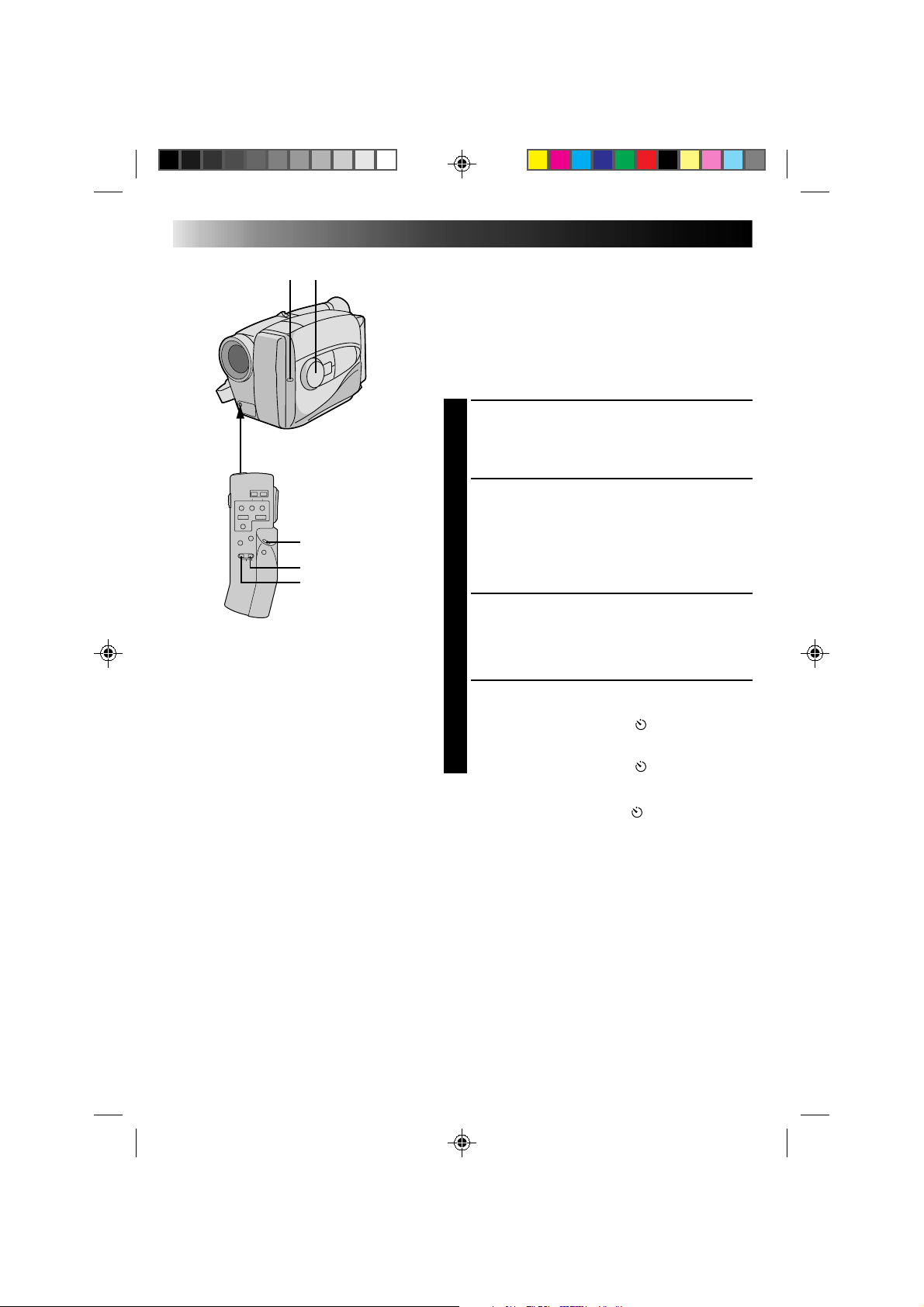
26
RECORDING
Advanced Features
Self-Timer
You can set the delay between pressing Recording Start/
Stop and the actual start of recording. If you secure the
camcorder, you (or whomever is operating the
camcorder) can enter the scene before recording starts.
NOTE:
You need the optional RM-V20U remote control unit to
perform this procedure.
ENGAGE RECORD–STANDBY
MODE
1
Make sure the lens cover is open, set the power
switch to CAMERA.
SET TIME DELAY
2
On the RM-V20U, press INTERVAL to set the delay
time. There are four choices, and they appear in the
viewfinder in the following order (each time
INTERVAL is pressed): 15S (15 seconds), 30S
(30 seconds), 1MIN (1 minute) and 5MIN
(5 minutes). Pressing again releases the Self-timer.
START DELAYED RECORDING
3
Press Recording Start/Stop. The tally lamp begins
blinking, and the blinking speed increases about
5 seconds before recording starts. When recording
begins, the lamp stops blinking but stays lit.
RELEASE SELF-TIMER MODE
4
To release when the tally lamp is not blinking, press
INTERVAL continuously until “ ” disappears. To
release when the tally lamp is blinking, press
Recording Start/Stop to stop the blinking, then press
INTERVAL continuously until “ ” disappears.
NOTE:
If the PROGRAM AE dial is set to “ ”, 15S is
automatically selected.
Tally lamp PROGRAM AE
RM-V20U (optional)
START/STOP
INTERVAL
REC TIME

27
Animation
Give stationary scenes or objects an illusion of
movement. This function allows you to shoot a
series of pictures, each slightly different, of the same
object for a brief period of time.
NOTE:
You need the optional RM-V20U remote control
unit to perform the following procedure.
ENGAGE RECORD–STANDBY
MODE
1
Make sure the lens cover is open, then set the
power switch to CAMERA.
SET RECORDING SPEED
2
Set SP/EP to SP (Z pg. 11).
SET RECORDING TIME
3
Press REC TIME on the remote control. Three
choices are available, and they appear in the
following order (each time REC TIME is
pressed): 1/4S (one-fourth of a second), 1/2S
(one-half of a second) and 1S (one full second).
Press again to release the animation mode.
START RECORDING
4
Press Recording Start/Stop after focusing on the
subject. The recording stops automatically after
the selected period of time.
ASSEMBLE SERIES OF
PICTURES
5
Repeat steps 3 and 4 for the desired number of
pictures.
CHECK YOUR WORK
6
Play back the series of pictures to see if the
results were satisfactory.
RELEASE ANIMATION MODE
7
Press REC TIME until “ ” disappears from the
viewfinder.
NOTES:
●
For best results, make sure the camcorder is
secured when shooting.
●
If the PROGRAM AE dial is set to Self-Timer
mode, Animation is cancelled and Self-Timer
mode is engaged with 15S selected.
●
Fade-in/out cannot be performed during
Animation shooting.
Time-Lapse
You can record sequentially at preset time spans.
Leaving the camcorder aimed at a specific subject,
you can record subtle changes over an extended
period of time.
NOTE:
You need the optional RM-V20U remote control
unit to perform the following procedure.
ENGAGE RECORD–STANDBY
MODE
1
Make sure the lens cover is open, then set the
power switch to CAMERA.
SET RECORDING SPEED
2
Set SP/EP to SP (Z pg. 11).
SET RECORDING TIME
3
Press REC TIME on the remote control. There
are three choices available, and they appear in
the following order (each time REC TIME is
pressed): 1/4S, 1/2S and 1S. Press again to
reset.
SET INTERVAL BETWEEN
RECORDINGS
4
Press INTERVAL on the remote control. There
are four choices available, and they appear in
the following order (each time INTERVAL is
pressed): 15S, 30S, 1MIN, and 5MIN. Press
again to reset.
START TIME-LAPSE
RECORDING
5
Press Recording Start/Stop. Recording and
intervals alternate automatically.
RELEASE TIME-LAPSE MODE
6
To release when the tally lamp is not blinking,
press INTERVAL and REC TIME repeatedly
until “ ” and “ ” disappear. To release
when the tally lamp is blinking, press
Recording Start/Stop to stop the blinking, then
press INTERVAL and REC TIME repeatedly
until “ ” and “ ” disappear.
NOTES:
●
Fade-in/out cannot be performed during
Time-Lapse shooting.
●
For best results, keep the camcorder secured
while shooting.
●
If, during steps 3 and 4, the PROGRAM AE dial is
set to the Self-Timer mode, the Self-Timer mode is
engaged with 15S selected.
28
+
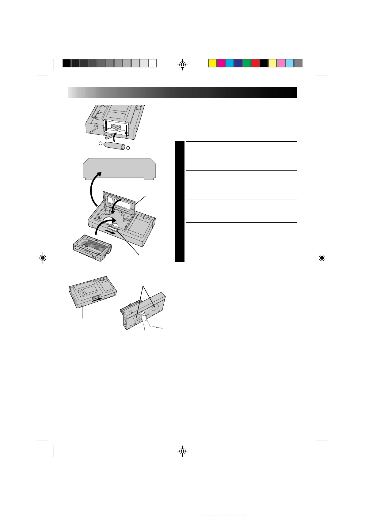
PLAYBACK
Using The Cassette Adapter
Cassette Adapter (VHS PlayPak)
Use this to play back a VHS-C video cassette recorded
with this camcorder. It is fully compatible with any VHS
video cassette recorder. The C-P7U adapter is battery
powered and automatically performs tape loading and
unloading.
INSERT BATTERY
1
Slide the battery cover up to remove it, and install
one “AA(R6)” size battery as shown in the
illustration at left. Then reattach the cover.
INSERT CASSETTE IN ADAPTER
2
Slide the latch to open the adapter compartment
door, then insert the cassette and close the
compartment door.
PLAY BACK ON CONNECTED VCR
3
Load the cassette adapter into the VCR and play the
tape back as you would any other.
REMOVE CASSETTE FROM
ADAPTER
4
Slide the latch and the compartment door opens
automatically. Then insert your finger in the hole on
the underside of the adapter as shown in the
illustration at left, push up and remove the cassette.
NOTES:
●
During tape loading and unloading, do not touch the
reels for safety and tape protection.
●
During special-effect playback (slow motion, still
frame, etc.), the picture may vibrate or noise bars may
appear on the screen.
●
To record on a VCR using a compact cassette and the
adapter, cover the adapter’s recording safety hole with
adhesive tape.
VCR
Compartment door
Sliding latch
Compact video cassette
Recording safety hole
Reels
29
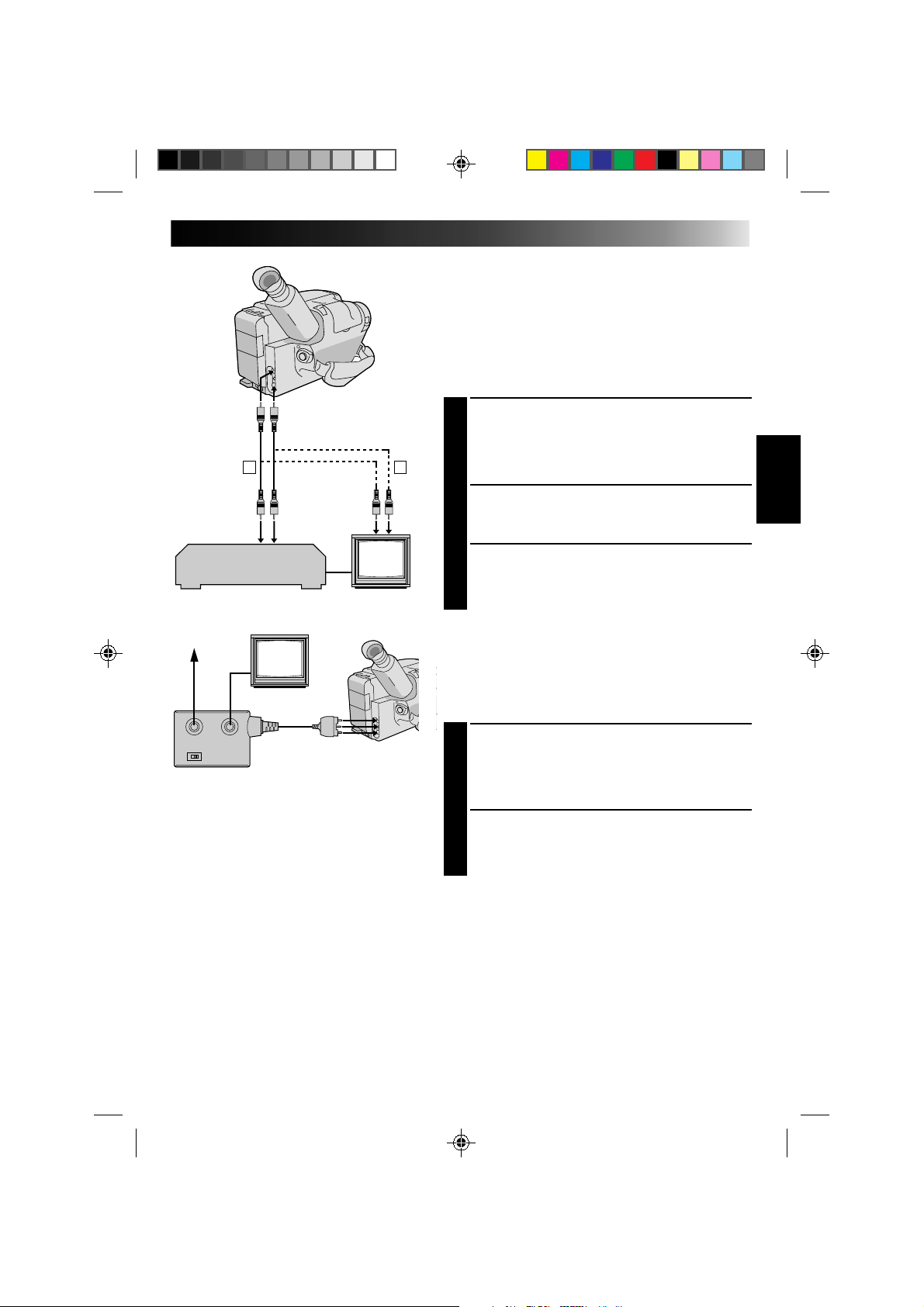
A
B
There are three basic types of connections. When making
the connections, refer also to your VCR and TV
instruction manuals.
Connection To A VCR [A]
(Editing, Dubbing and Playback)
NOTE:
Use the optional Audio and Video cables.
CONNECT CAMCORDER TO VCR
1
As shown in the illustration at left, connect the
optional Audio and Video cables between the
AUDIO and VIDEO connectors on the camcorder
and those on the VCR.
SUPPLY POWER
2
Turn on the camcorder, the VCR and the TV.
SELECT MODE
3
Set the VCR to its AUX input mode, and set the TV
to its VIDEO mode or channel 3.
Connection To A TV With A/V Input
Connectors [B] (Playback ONLY)
NOTE:
Use the optional Audio and Video cables.
CONNECT CAMCORDER TO TV
1
As shown in the illustration at left, connect the
optional Audio and Video cables between the
AUDIO and VIDEO connectors on the camcorder
and those on the TV.
SELECT MODE
2
Set the TV to its VIDEO or AV mode (as specified in
its instructions).
Connection To A TV With NO A/V Input
Connectors (Playback ONLY)
NOTE:
Use the optional RF-V5U RF unit.
* Refer to the RF-V5U instruction manual for connection
procedure.
NOTES:
●
It is recommended to use the AC Power
Adapter/Charger as the power supply instead
of the battery pack.
●
To monitor the picture and sound from the
camcorder without inserting a tape, set the
camcorder’s power switch to CAMERA, then
set your TV to the appropriate input mode.
●
If you have a TV or speakers that are not
specially shielded, do not place the speakers
adjacent to the TV as interference will occur
in the camcorder playback picture.
To AUDIO
and VIDEO
connectors
Audio and Video
cables (optional)
To AUDIO and
VIDEO IN
connectors
Aerial
RF unit RF-V5U
(optional)
To AUDIO, VIDEO and
DC OUT connectors
VCR
PLAYBACK
Basic Connections
30
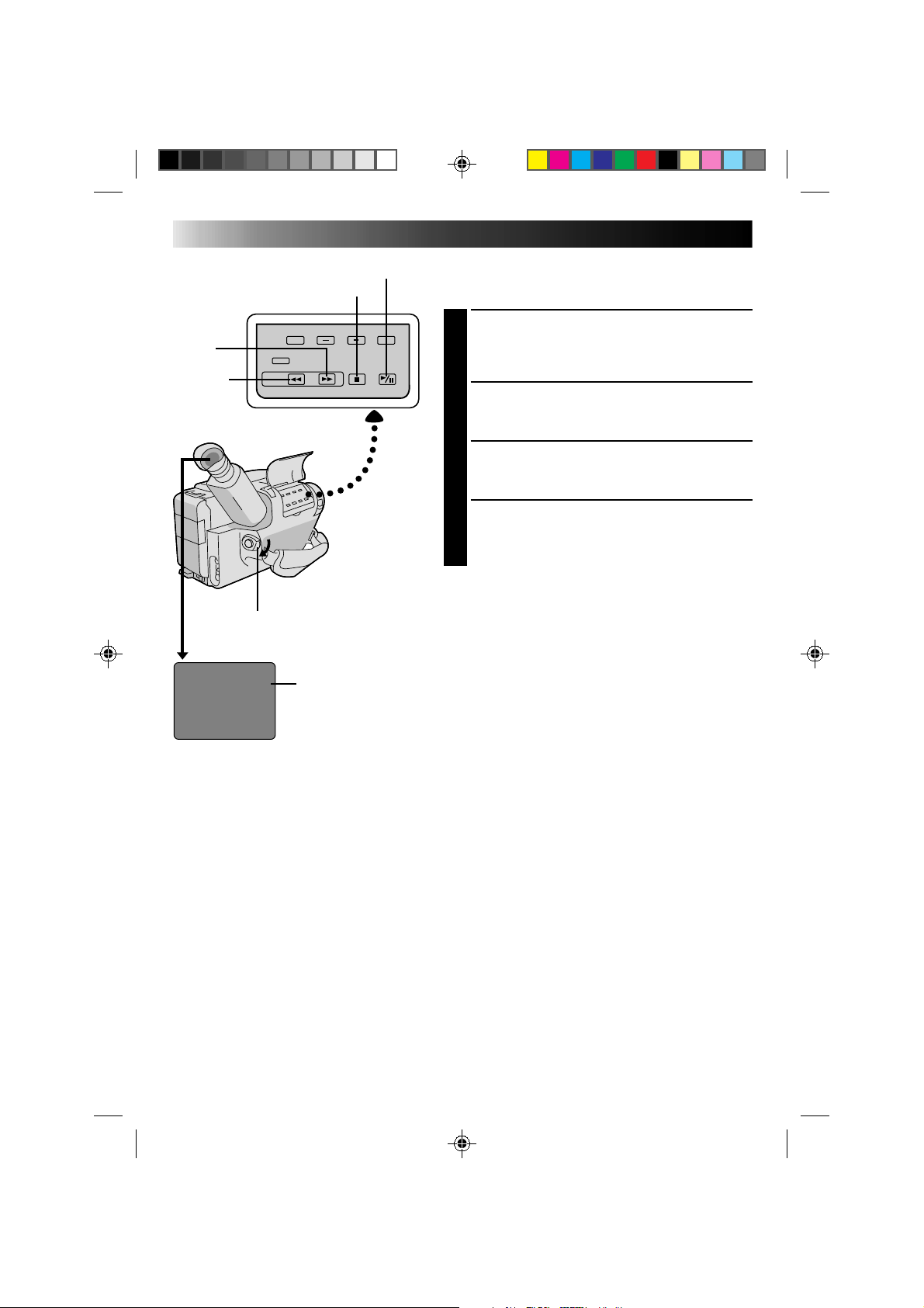
M 0:00:00
PLAYBACK
Basic Playback
NOTE:
Make sure you connect your camcorder as directed in
“BASIC CONNECTIONS” (
Z
pg. 29 ).
LOAD A CASSETTE
1
Slide EJECT to open the cassette holder, then insert
the cassette with the label facing out. Press PUSH to
ensure the holder is closed and locked.
SELECT MODE
2
Set the power switch to PLAY. The Power On
indicator lights.
PLAYBACK
3
Press PLAY/PAUSE. The playback picture appears in
the viewfinder and the connected TV.
STOP PLAYBACK
4
Press STOP.
Rewind or Fast-forward the tape
Press REW to rewind, or FF to fast-forward the tape
during Stop mode.
NOTE:
The camcorder shuts off automatically after about 5
minutes in STOP mode. To turn on again, set the power
switch to POWER OFF, then to PLAY.
FF
REW
POWER
PLAY/PAUSE
STOP
Tape counter
 Loading...