


 Loading...
PLASMA DISPLAY MONITOR
BEDIENUNGSANLEITUNG : PLASMABILDSCHIRM
MANUEL D'INSTRUCTIONS : MONITEUR DE VISUALISATION PLASMA MANUALE D'ISTRUZIONI : MONITOR CON SCHERMO AL PLASMA MANUAL DE INSTRUCCIONES : MONITOR DISPLAY DE PLASMA
GM-V42E |
INSTRUCTIONS |
|
 ESPAÑOL ITALIANO FRANÇAIS DEUTSCH ENGLISH
MENU INPUT POWER |
LCT1390-001B |
INSTRUCTIONS
Model
GM-V42E
Thank you for purchasing this JVC Monitor.
Before using the monitor, read this manual carefully so that you know how to use the Monitor correctly.
Refer to this manual whenever questions or problems about operation arise. Be sure to read and observe the safety precautions.
Keep this manual where the user can see it easily.
*Installation and removal require special expertise. Consult your product dealer for details.
This instruction manual refers to the GM-V42PCE, GM-V42PCEG, GM-V42PCEB and GM-V42E.
The explanations and illustrations used in this instruction manual are of the GM-V42E unless otherwise stated. The differences between each model are as follows:
|
|
GM-V42E |
GM-V42PCE/GM-V42PCEG/GM-42PCEB |
Inputs VIDEO A |
Available |
Not available*1 |
|
|
VIDEO B |
Available |
Not available*1 |
|
COMPONENT/RGB B |
Available |
Not available*1 |
*1 These inputs will be available with the separately-purchased video input unit (IF-C42P1G). Ask your dealer to install the video input unit.
Contents
Page |
|
Safety Precautions .................................................... |
2 |
Parts Identification .................................................... |
4 |
• Remote Control ................................................... |
4 |
• Monitor: Front View ............................................. |
5 |
• Monitor: Rear Views ............................................ |
6 |
Preparations .............................................................. |
8 |
• Checking the Accessories ................................... |
8 |
• Installing the Batteries......................................... |
8 |
• Attaching the Ferrite Core ................................... |
8 |
Installation ................................................................. |
9 |
• Precautions ......................................................... |
9 |
Connections ............................................................ |
10 |
• Precautions ....................................................... |
10 |
• Available Signals ............................................... |
10 |
• Connection Diagrams ....................................... |
11 |
Basic Operations ..................................................... |
14 |
• Daily Operations ............................................... |
14 |
• Changing the Aspect Ratio ............................... |
15 |
Video Adjustments .................................................. |
16 |
• Adjusting the Picture Quality ............................. |
16 |
• Adjusting the Screen Size and Position ............ |
17 |
• Adjusting the Color Temperature ....................... |
19 |
• Adjusting the White Balance ............................. |
19 |
• Changing the Aspect Ratio ............................... |
21 |
• Setting the Receivable Signal Types ................. |
21 |
• Setting the COMPONENT/RGB B Input ........... |
22 |
• Changing the Resistance of the RGB B Input |
|
Terminals ........................................................... |
23 |
• Resetting the Function Selection Menu Settings .. |
23 |
|
Page |
Other Convenient Functions ................................... |
24 |
• Showing On-screen Display .............................. |
24 |
• Confirming the Use Time and Model Name ...... |
25 |
• Showing the On-screen When Changing |
|
the Input Mode .................................................. |
25 |
• Prohibiting the Monitor’s Button Operations ...... |
26 |
• Setting the Remote-Controllable Input .............. |
27 |
• Setting the High-Definition Signal Types ........... |
27 |
• Setting the Clock and the Power On/Off |
|
Timer ................................................................. |
28 |
• Using the Pixel Shift Function ........................... |
29 |
• Using the Power Save Function ........................ |
29 |
• Preventing the Afterimage Effect ...................... |
30 |
• Refreshing the Screen ...................................... |
31 |
• Checking the Timer Battery............................... |
32 |
• Resetting All the Setup Menu Settings ............. |
33 |
• Resetting All the Menu Settings ........................ |
33 |
Menu Classifications ............................................... |
34 |
• Main Menu ........................................................ |
34 |
• Setup Menu ....................................................... |
36 |
Troubleshooting ....................................................... |
38 |
• Self-diagnostic Indication .................................. |
39 |
Specifications .......................................................... |
40 |
ENGLISH
1
Safety Precautions
EUROPE EMC STANDARD NOTICE
■ GM-V42E
Warning: This is a class A product. In a domestic environment this product may cause radio interference in which case the user may be required to take adequate measure.
IMPORTANT INFORMATION
WARNING: TO REDUCE THE RISK OF FIRE AND ELECTRIC SHOCK, DO NOT EXPOSE THIS APPARATUS TO RAIN, MOISTURE, DRIPPING OR SPLASHING AND THAT NO OBJECTS FILLED WITH LIQUIDS, SUCH AS VASES, SHALL BE PLACED ON THE APPARATUS.
IMPORTANT SAFEGUARDS
Electrical energy can perform many useful functions. This unit has been engineered and manufactured to assure your personal safety. But IMPROPER USE CAN RESULT IN POTENTIAL ELECTRICAL SHOCK OR FIRE HAZARD. In order not to defeat the safeguards incorporated into this product, observe the following basic rules for its installation, use and service. Please read these “Important Safeguards” carefully before use.
–All the safety and operating instructions should be read before the product is operated.
–The safety and operating instructions should be retained for future reference.
–All warnings on the product and in the operating instructions should be adhered to.
–All operating instructions should be followed.
–Unplug this product from the wall outlet before cleaning. Do not use liquid cleaners or aerosol cleaners. Use a damp cloth for cleaning.
– Use a vacuum cleaner to get rid of the dust around the intakes (all the openings) on the rear. If a vacuum is not available, use a cloth and wipe it off. Failure to do so will cause internal heat buildup and, therefore, cause damage to the product.
– Do not use attachments not recommended by the product manufacturer as they may be hazardous.
– Do not use this product near water. Do not use immediately after moving from a low temperature to high temperature, as this causes condensation, which may result in fire, electric shock, or other hazards.
–Do not place this product on an unstable cart, stand, or table. The product may fall, causing serious injury to a child or adult, and serious damage to the product. The product should be mounted according to the manufacturer’s instructions, and should use a mount recommended by the manufacturer.
–When the product is used on a cart, care should be taken to avoid quick stops, excessive force, and uneven surfaces which may cause the product and cart to overturn, damaging equipment or causing possible injury to the operator.
–Slots and openings in the cabinet are provided for ventilation. These ensure reliable operation of the product and protect it from overheating. These openings must not be blocked or covered. (The openings
should never be blocked by placing the product on bed, sofa, rug, or similar surface. It should not be placed in a built-in installation such as a bookcase or rack unless proper ventilation is provided and the manufacturer’s instructions have been adhered to.)
For proper ventilation, separate the product from other equipment, which may prevent ventilation and keep distance more than 10 cm.
–This product should be operated only with the type of power source indicated on the label. If you are not sure of the type of power supply to your home, consult your product dealer or local power company.
2
– For United Kingdom: This product is equipped with a three-wire plug. This plug will fit only into a grounded power outlet. If you are unable to insert the plug into the outlet, contact your electrician to install the proper outlet. Do not defeat the safety purpose of the grounded plug.
–Power-supply cords should be routed so that they are not likely to be walked on or pinched by items placed upon or against them. Pay particular attention to cords at doors, plugs, receptacles, and the point where they exit from the product.
–For added protection of this product during a lightning storm, or when it is left unattended and unused for long periods of time, unplug it from the wall outlet and disconnect the cable system. This will prevent damage to the product due to lightning and power line surges.
–Do not overload wall outlets, extension cords, or convenience receptacles on other equipment as this can result in a risk of fire or electric shock.
–Never push objects of any kind into this product through openings as they may touch dangerous voltage points or short out parts that could result in a fire or electric shock. Never spill liquid of any kind on the product.
–Do not attempt to service this product yourself as opening or removing covers may expose you to dangerous voltages and other hazards. Refer all service to qualified service personnel.
–Unplug this product from the wall outlet and refer service to qualified service personnel under the following conditions: a)When the power supply cord or plug is damaged.
b)If liquid has been spilled, or objects have fallen on the product.
c) If the product has been exposed to rain or water.
d)If the product operated normally by following the operating instructions. Adjust only those controls that are covered by the Operation Manual, as an improper adjustment of controls may result in damage and will often require extensive work by a qualified technician to restore the product to normal operation.
e)If the product has been dropped or damaged in any way.
f) When the product exhibits a distinct change in performance – this indicates a need for service.
–When replacement parts are required, be sure the service technician has used replacement parts specified by the manufacturer or with same characteristics as the original part. Unauthorized substitutions may result in fire, electric shock, or other hazards.
–Upon completion of any service or repairs to this product, ask the service technician to perform safety checks to determine that the product is in proper operating condition.
–The product should be placed more than 30 cm away from heat sources such as radiators, heat registers, stoves, and other products (including amplifiers) that produce heat.
–When connecting other products such as VCR’s, and personal computers, you should turn off the power of this product for protection against electric shock.
–Do not place combustibles behind the cooling fan. For example, cloth, paper, matches, aerosol cans or gas lighters that present special hazards when over heated.
–Use only the accessory cord designed for this product to prevent shock.
–Do not touch the handles on the rear soon after many hours of continuous use. They are so hot and will cause a burn on the hand. If you need to touch the handles, for example, to move the product, wait until the handles are cooled enough.
– Option terminal: This terminal is intended exclusively to be used to drive the fan motor.
Do not connect any plugs to the terminal other than JVC’s recommended optional parts.
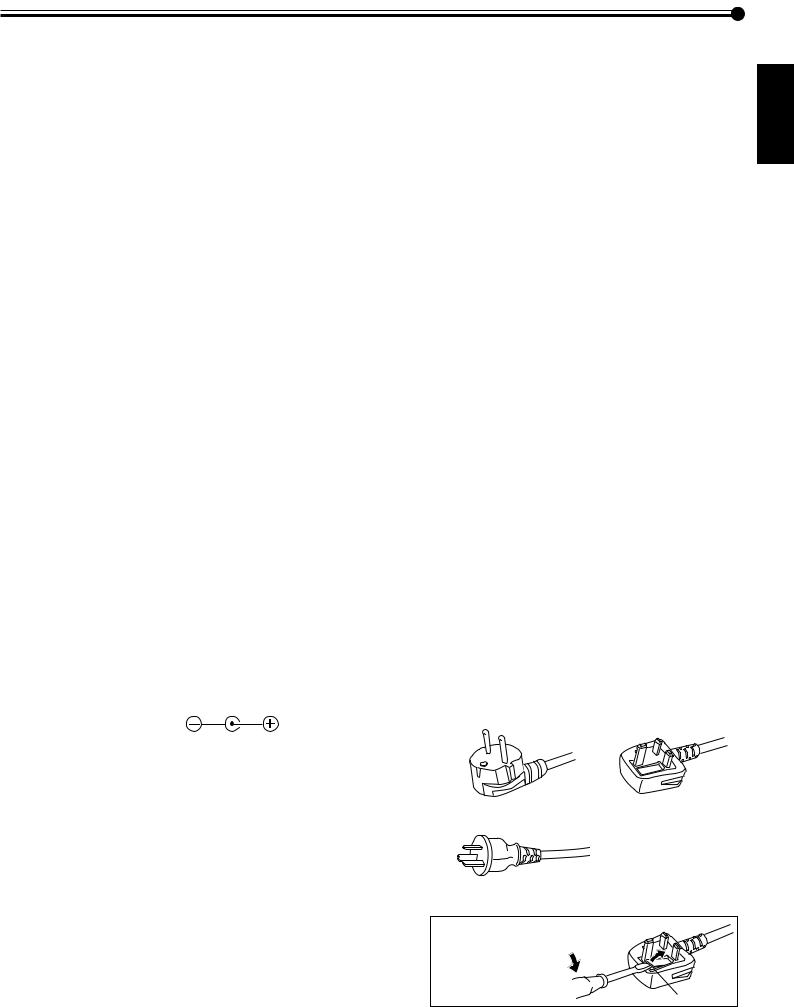
Polarity of terminal
POWER CONNECTION
The power supply voltage rating of this product is AC 220 – 240 V. The power cords attached conform to the following power supply voltage and countries. Use only the power cord designated to ensure Safety and EMC regulations of each country.
Note for the United Kingdom power cord only
The plug on the United Kingdom power cord has a built-in fuse. When replacing the fuse, be sure to use only a correctly rated approved type, re-fit the fuse cover. (Consult your dealer or qualified service personnel.)
For European countries: |
For United Kingdom: |
AC 220 – 240 V |
AC 220 – 240 V |
For Australia:
AC 220 – 240 V
How to replace the fuse |
|
Open the fuse |
|
compartment with the |
|
blade screw driver, and |
|
replace the fuse. |
Fuse |
|
ENGLISH
3
Parts Identification
Remote Control
1 2
2
RM–C579 REMOTE CONTROL UNIT
RM–C579 REMOTE CONTROL UNIT
OFF |
POWER |
ON |
DISPLAY |
|
ASPECT |
INPUT SELECT |
||
A |
|
COMPO. |
|
/(RGB B) |
|
|
|
|
VIDEO |
|
|
B |
|
RGB A |
MUTING |
VOLUME |
|
MENU/EXIT
3OFF POWER ON
DISPLAY ASPECT
4 |
9 |
INPUT SELECT
|
A |
COMPO. |
|
5 |
/(RGB B) |
||
|
|||
VIDEO |
|
||
|
|
||
|
B |
RGB A |
|
|
MUTING |
VOLUME |
6


 p
p
7
8
MENU/EXIT
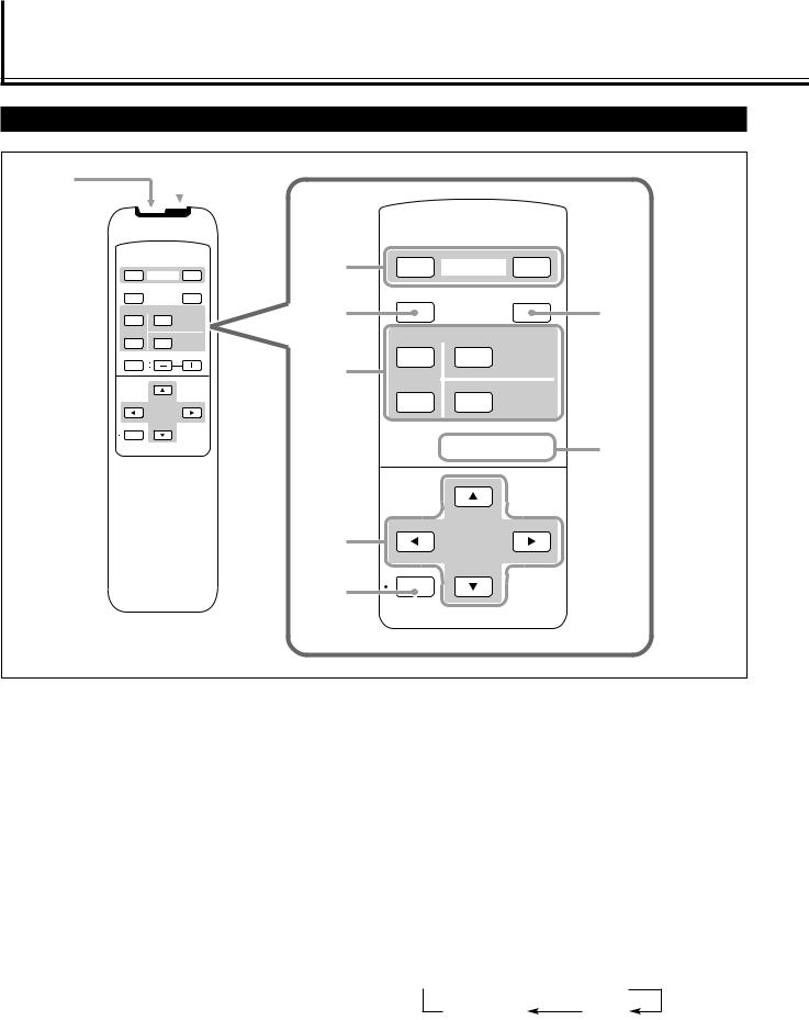
1Remote control cable jack (page 11)
Connect the remote control cable (not supplied) when using this remote control as a wired remote control.
2 Remote signal transmission window
3POWER ON/OFF button (page 14)
Use this button to turn on/off the Monitor.
4DISPLAY button (page 14)
Use this button to display the input terminal, color system (for VIDEO A or VIDEO B input), scan system (for COMPONENT input) and horizontal/vertical frequency (for RGB A and RGB B input).
Pressing the button again will make the display disappear.
5INPUT SELECT (VIDEO A, VIDEO B, COMPO./(RGB B) and RGB A) buttons
(page 14)
Use these buttons to switch between inputs.
To select the COMPONENT or RGB B input, you have to set “RGB/COMPO.” correctly on the menu (see page 22).
•Only for GM-V42PCE, GM-V42PCEG and GM-V42PCEB: Only RGB A input can be used.
To reproduce images through the other inputs, you need to install video input unit (IF-C42P1G), which is separately purchased.
6MUTING button (page 14)
Use this button to turn off the volume immediately. Pressing the button again will resume the previous volume level.
72 / 3 / 5 / ∞ buttons
Use these buttons to select menu items or make adjustments.
8MENU/EXIT button
Use this button to display or erase menus.
While a sub-menu is displayed, pressing this button will move you one screen back to the preceding menu.
9ASPECT button (page 15)
Use this button to switch between aspect ratios. Each time you press the button, the aspect ratio changes as follows:
 REGULAR
  FULL
FULL
PANORAMIC ZOOM
pVOLUME + / – buttons (page 14)
Use these buttons to adjust the volume level.
•The VOLUME – button can be also used to display the Setup Menu (see page 25).
4
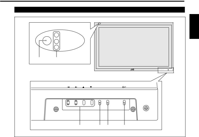
Monitor: Front View
|
|
|
ENGLISH |
1 |
2 |
|
|
|
|
|
MENU INPUT |
|
|
MENU INPUT |
|
Bottom View |
3 |
4 5 |
6 |
1Remote sensor/power lamp
Point the front end of the wireless remote control toward here.
When the Monitor is turned on, the power lamp glows green. It glows orange in standby mode.
2Self-diagnostic lamps (page 39)
These lamps light/flash if something abnormal occurs with the Monitor.
32 / 3 / 5 / ∞ buttons
Use these buttons to select menu items and to make adjustments.
•When no menu is displayed, you can use the 2 / 3 buttons to adjust the volume level.
4MENU button
Use this button to display or erase menus.
While a sub-menu is displayed, pressing this button will move you one screen back to the preceding menu.
5INPUT button (page 14)
Use this button to switch between inputs.
To select the COMPONENT or RGB B input, you have to set “RGB/COMPO.” correctly on the menu (see page 22).
•Only for GM-V42PCE, GM-V42PCEG and GM-V42PCEB: Only RGB A input can be used.
To reproduce images through the other inputs, you need to install video input unit (IF-C42P1G), which is separately purchased.
6 button (page 14)
Use this button to turn on and off the Monitor.
5
Parts Identification (Continued)
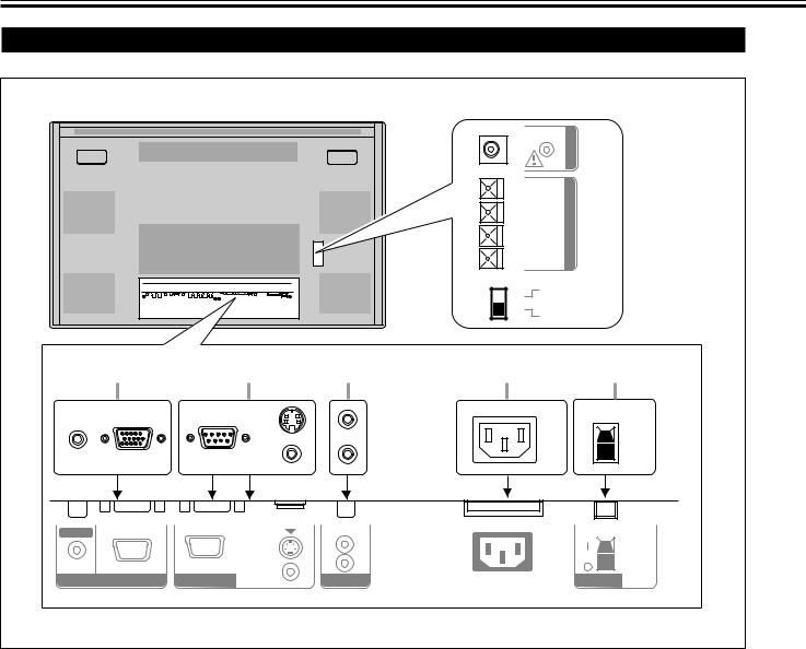
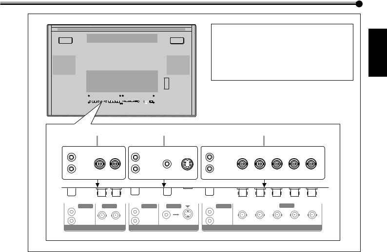
Monitor: Rear Views
|
|
|
|
|
OPTION |
6 |
|
|
|
|
|
|
|
|
|
|
|
9 |
|
7 |
|
|
|
|
L |
OUT |
|
|
|
|
|
( |
SPEAKER |
|
|
|
|
|
( |
|
|
|
|
|
|
R |
|
|
|
|
|
|
9 |
|
|
|
|
|
|
EXTERNAL |
8 |
|
|
|
|
|
INTERNAL |
|
|
1 |
|
2 |
3 |
4 |
|
5 |
AUDIO |
|
|
OUT |
|
|
|
|
|
MAKE |
L |
|
|
|
|
|
|
|
|
|
|
IN |
RS-232C |
WIRED |
R |
|
|
|
RGB A |
REMOTE |
AUDIO |
AC IN |
|
POWER |
|
|
|
|||||
1RGB A input terminals (page 11)
•D-sub, 15 pin
Connect to the video output terminal of a personal computer.
•AUDIO IN (stereo mini jack)
Connect to the audio output terminal of a personal computer.
2REMOTE terminals (pages 11 and 13)
•RS-232C (D-sub, 9 pin)
Connect to the RS-232C terminal of a personal computer. For the control method using this terminal, consult an authorized JVC dealer.
•MAKE terminal (mini DIN 4pin)
Connect an external control unit. (See page 13.)
•WIRED terminal (stereo mini jack)
Connect a wired remote control unit to this terminal.
Note:
•When the above three terminals are used at the same time, transmitted commands through the MAKE terminal have priority over those through the other terminals.
3AUDIO OUT terminals (pin jack) (page 11)
Connect to the audio input terminals of external equipment such as an amplifier.
4AC IN terminal (page 11)
Connect the supplied power cord to this terminal.
5POWER switch (page 14)
Setting this switch to “| (on)” will put the Monitor into standby mode, allowing you to turn on and off the power using the POWER or  button either on the remote control or on the Monitor.
6OPTION terminal (page 13)
Connect the power cord of the Cooling Fan Unit (not supplied) when installing the Monitor vertically.
7SPEAKER OUT L/R terminals (page 11)
Connect external speakers, such as unique JVC speakers (not supplied), etc.
8 INTERNAL/EXTERNAL (built-in speaker/external speaker) selecting switch (page 11)
INTERNAL: |
To use built-in speakers. |
EXTERNAL: |
To use external speakers. |
6
Note:
* GM-V42PCE, GM-V42PCEG and GM-V42PCEB do not have the following input terminals— VIDEO A, VIDEO B, and COMPONENT/RGB B. To input video, S-video, and component signals, you need to install video input unit (IF-C42P1G), which is separately purchased.
|
|
|
|
|
|
|
|
|
|
|
|
|
|
|
|
|
|
|
|
|
|
|
|
|
|
|
|
|
|
|
|
|
|
|
|
|
|
|
|
|
|
|
|
|
|
|
|
|
|
|
|
9 |
|
|
p |
|
q |
||
AUDIO |
VIDEO |
AUDIO |
VIDEO |
|
AUDIO |
|
|
VIDEO |
L/MONO |
|
L/MONO |
|
|
L/MONO |
|
|
|
R IN |
OUT |
R |
IN |
Y/C IN |
R |
Y/G |
Pb/B |
Pr/R HD/Cs VD |
VIDEO A |
|
|
VIDEO B |
|
|
COMPONENT/RGB B |
||
ENGLISH
9 VIDEO A terminals (page 12) |
q COMPONENT/RGB B input terminals (page 12) |
|
• AUDIO (L/MONO, R) input terminals (pin jack) |
• AUDIO (L/MONO, R) input terminals (pin jack) |
|
Connect these terminals to the audio input terminals of a |
Connect these terminals to the audio output terminals of |
|
VCR, etc. |
the other equipment. |
|
• VIDEO IN terminal (BNC) |
• G, B, R, HD/Cs, VD (VIDEO) input terminals (BNC) |
|
Connect this terminal to the video output terminal of a |
Connect these terminals to the following output |
|
VCR, etc. |
terminals of a personal computer or other equipment: |
|
• VIDEO OUT terminal (BNC) |
– Analog RGB signal output terminals |
|
Connect this terminal to the video input terminal of |
– Horizontal sync (HD) signal or composite (Cs) signal |
|
another Monitor. |
output terminal |
|
Note: |
– Vertical sync (VD) signal output terminal |
|
Notes: |
||
• Since the video output terminals on this Monitor are |
||
loop-through terminals, the devices connected to this |
• External sync signals are automatically detected when |
|
video output terminal should be correctly terminated. |
they come in. |
|
Otherwise, pictures become abnormally bright or the |
• When both horizontal (HD)/vertical (VD) sync and |
|
Monitor screen gets affected abnormally. |
composite (Cs) sync are connected, HD/VD sync signals |
|
|
will be used. |
|
p VIDEO B terminals (page 12) |
|
•AUDIO (L/MONO, R) input terminals (pin jack)
Connect these terminals to the audio output terminals of a VCR, etc.
•Y/C (S video) IN terminal (mini DIN 4pin)
Connect this terminal to the S-video output terminal of a VCR, etc.
•VIDEO IN terminal (pin jack)
Connect this terminal to the video output terminal of a VCR, etc.
Note:
•When both the video and S-video terminals are connected, the S-video terminal will have priority.
•Y, Pb, Pr (VIDEO) input terminals (BNC)
Connect these terminals to the component signal output terminals of NTSC or high-vision equipment.
Note:
•When these terminals are used as the component terminals (Y, Pb, Pr)—see “Setting the COMPONENT/ RGB B Input” on page 22, external sync signals (HD/Cs, VD) cannot be used.
7
Preparations
Checking the Accessories
The following accessories are included with the Monitor. Check for them. If any item is missing, please contact the dealer where you purchased the Monitor.
•Remote control (RM-C579) x 1
•Power cord x 2 (3 for Australia) (Use the one matching the wall outlet.)
•Batteries (AA/R6P) x 2
•BNC-RCA convension plug x 3 (For Australia)
•Ferrite core x 1 (Except for GM-V42PCEB)
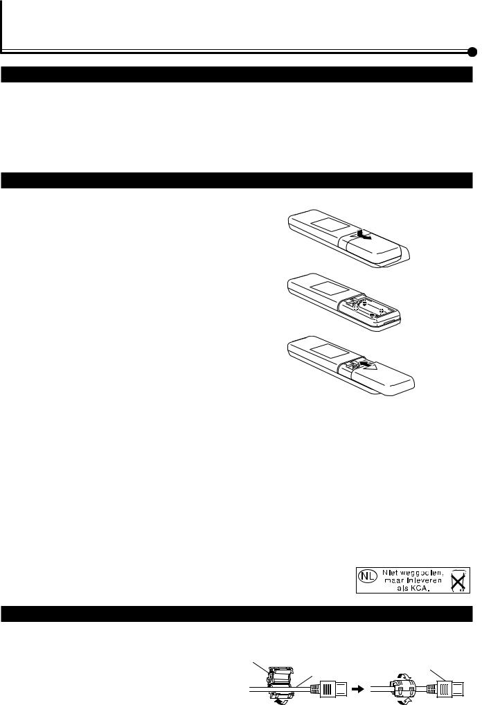
Installing the Batteries
Put the batteries in the remote control as follows. If the remote control has become erratic in operation, change the batteries.
1
2
3
Remove the back cover.
While pushing the release lever on the cover, remove the cover in the direction of the arrow.
Place the batteries.
Put the two supplied batteries (AA/R6P), noting the ª and · markings, as shown.
Replace the back cover as illustrated.
Make sure the release lever on the cover is locked in place correctly.
Precautions for using batteries
If batteries are used improperly, the liquid could leak out, causing a fire, injury, etc. or dirtying the vicinity. Take notice of the following:
•Do not mix old and new batteries.
•Do not mix different types of battery as different types may have different characteristics.
•Place the batteries according to the ª and · markings indicated on the battery compartment.
•When installing the batteries, insert the · end first to avoid a short circuit.
•Use only the specified batteries.
•When you are not using the remote control for a long time, remove the batteries.
•When the batteries have reached the end of their life, replace them with new ones immediately. Otherwise, the liquid may leak out, or malfunction may be caused by
the leaked liquid. If the leaked liquid contacts your skin, wipe off the liquid with a soft cloth. If the affected skin is left as is, you may get a rough skin.
• Do not throw the batteries into fire or try recharging them.
• The service life of batteries is six months to one year for normal use. The supplied batteries are only for checking the operation and their life may be shorter. When the remote control operation becomes erratic, replace with new batteries.
Attaching the Ferrite Core (For GM-V42PCE, GM-V42PCEG, and GM-V42S)
Attach the ferrite core to the power cord. Using the power cord without the ferrite core may lead to noise (interference). Open the ferrite core, insert the power cord and close the ferrite core. Attach the ferrite core to the AC IN end of the power cord.
Ferrite core *
Plug to AC IN
Power cord
* Not supplied to GM-V42PCEB
8
Installation
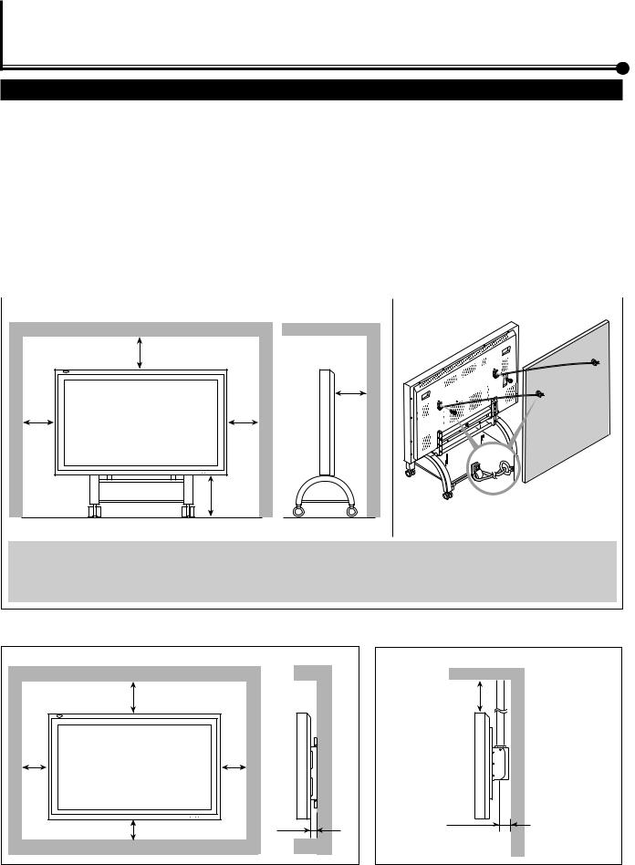
Precautions
• When mounting the Monitor vertically, consult your dealer. (See also page 13.) |
|
||
|
|||
• When installing the Monitor, be sure to use a dedicated Stand Unit, Wall Mounting Unit, or Monitor Hanger Unit, depending |
ENGLISH |
||
on a particular case. Ask your dealer for installation. |
|
|
|
|
|
|
|
• When installing the Monitor, refer also to the user manual for each option to use. Do not tilt the Monitor rightward, leftward, |
|
||
or backward. |
|
|
|
• Route the power cord and connection cables along wall or floor corners to avoid walking on them. |
|
||
• For good heat dissipation, try to leave the following distances of space (minimum) around the Monitor. |
|
||
• The ambient temperature of the installation place should be within the range of 0˚C to 40˚C (slightly variable depending on |
|
||
|
|||
ambient conditions for installation.) |
|
|
|
• When installing the Monitor in a place, such as near the ceiling, the remote control may not work correctly because of possible |
|
||
effects from the surroundings. If this happens, use the remote control as a wired remote control or move the Monitor where it |
|
||
is free from these effects. |
|
|
|
When installing the Monitor on a stand |
|
|
|
|
|
|
|
Front View |
Side View |
|
|
Wall
150
Unit: mm
Take measures against the Monitor from overturning:
To protect against abnormal events such as earthquakes and to prevent unexpected accidents, take appropriate measures for preventing the Monitor from overturning; should it overturn, this could lead to personal injury.
For detailed information, refer to the manual supplied for the stand.
When mounting the Monitor on the wall |
When hanging the Monitor from the ceiling |
Front View |
|
Side View |
100 |
|
100 |
Unit: mm |
100 |
50 |
|
||
Notes: |
|
|
Side View
Unit: mm
•Do not allow the same image (pattern) to be continuously displayed on the screen for a long time; otherwise, the area on the screen corresponding to the image may vary in brightness, leaving an afterimage on the screen. To reduce the afterimage, you can use the Refresh function (see page 31).
•The Monitor is manufactured using very high-precision technology, allowing for more than 99.99% active pixels, however, be aware that only a slight number of pixels may be deficient or lit at all times.
•Do not install the Monitor in such a way that the Monitor and other AV equipment affect each other adversely. (For example, if a disturbed image or noise due to electromagnetic interference occurs, or if the infrared remote control malfunctions, change the installation place.)
9
Connections
Precautions
•Before making connections, turn off all the equipment.
•Plugs should be firmly inserted; poor connection could cause noise.
•To unplug a cord, be sure to grasp its plug and pull it out.
•Connect the power cord after having finished all other connections.
•Refer also to the user manual of each piece of equipment.
Available Signals
Video signals
The following signals can be input to this Monitor:
•VIDEO A and VIDEO B terminals accept — PAL, PAL60, NTSC, NTSC4. 43, and SECAM signals.
•COMPONENT/RGB B terminals accept — 480i, 576i, 480p, 576p, 720/60p, 1080/50i, and 1080/60i (1035/60i) signals. (You
need to set “RGB/COMPO.” to “COMPO.” on the menu (see page 21).
(For GM-V42PCE, GM-V42PCEG and GM-V42PCEB, to input the above signals, you need to install the video input unit (IF-C42P1G), which is separately purchased.)
Computer signals (Preset)
This Monitor has 18 preset video modes for the most popular industrial standard, and the signals of the following image resolutions can be input to the RGB input terminals.
No. |
Signal name |
Screen resolution |
Horizontal |
Vertical |
Scan system |
||
Horizontal |
Vertical |
Frequency (kHz) |
Frequency (Hz) |
||||
|
|
|
|||||
|
|
|
|
|
|
|
|
1 |
PC98 |
640 |
400 |
24.8 |
56.4 |
Non-interlace |
|
|
|
|
|
|
|
|
|
2 |
VGA400-70 |
640 |
400 |
31.5 |
70.1 |
Non-interlace |
|
|
|
|
|
|
|
|
|
3 |
VGA480-60 |
640 |
480 |
31.5 |
59.9 |
Non-interlace |
|
|
|
|
|
|
|
|
|
4 |
VGA480-72 |
640 |
480 |
31.7 |
72.8 |
Non-interlace |
|
|
|
|
|
|
|
|
|
5 |
VGA480-75 |
640 |
480 |
37.5 |
75.0 |
Non-interlace |
|
|
|
|
|
|
|
|
|
6 |
WVGA-60 |
852 |
480 |
31.7 |
60.3 |
Non-interlace |
|
|
|
|
|
|
|
|
|
7 |
MAC13” |
640 |
480 |
35.0 |
66.7 |
Non-interlace |
|
|
|
|
|
|
|
|
|
8 |
SVGA-56 |
800 |
600 |
35.2 |
56.3 |
Non-interlace |
|
|
|
|
|
|
|
|
|
9 |
SVGA-60 |
800 |
600 |
37.9 |
60.3 |
Non-interlace |
|
|
|
|
|
|
|
|
|
10 |
SVGA-72 |
800 |
600 |
48.1 |
72.2 |
Non-interlace |
|
|
|
|
|
|
|
|
|
11 |
SVGA-75 |
800 |
600 |
46.9 |
75.0 |
Non-interlace |
|
|
|
|
|
|
|
|
|
12 |
XGA-60 |
1024 |
768 |
48.4 |
60.0 |
Non-interlace |
|
|
|
|
|
|
|
|
|
13 |
XGA-70 |
1024 |
768 |
56.5 |
70.1 |
Non-interlace |
|
|
|
|
|
|
|
|
|
14 |
XGA-75 |
1024 |
768 |
60.0 |
75.0 |
Non-interlace |
|
|
|
|
|
|
|
|
|
15 |
XGA-85 |
1024 |
768 |
68.7 |
85.0 |
Non-interlace |
|
|
|
|
|
|
|
|
|
16 |
XGA+-75 |
1152 |
864 |
67.5 |
75.0 |
Non-interlace |
|
|
|
|
|
|
|
|
|
17 |
RGB15K-60 |
— |
— |
15.7 |
59.9 |
Interlace |
|
|
|
|
|
|
|
|
|
18 |
RGB15K-50 |
— |
— |
15.6 |
50.0 |
Interlace |
|
|
|
|
|
|
|
|
|
Notes:
•When a signal other than listed above is input, a part of the screen may become void or an unnecessary picture may appear.
•Signals, though they are within the acceptable range of frequencies, may not be displayed normally, depending on the signal type.
•Depending on the connected equipment, the Monitor may not be compatible with composite sync (Cs) or G on sync signals.
•When a preset mode signal is input, the vertical frequency displayed on the screen will have an “*” shown at its right top position.
•When the No. 6 signal is input, change the aspect ratio to “FULL” with the ASPECT button (page 15) on the remote control or from the “FUNCTION SELECT” menu (page 21).
•When No. 8 to No. 16 signals are input, thin lines may become obscure for their signal frequencies are higher than the screen resolution.
10
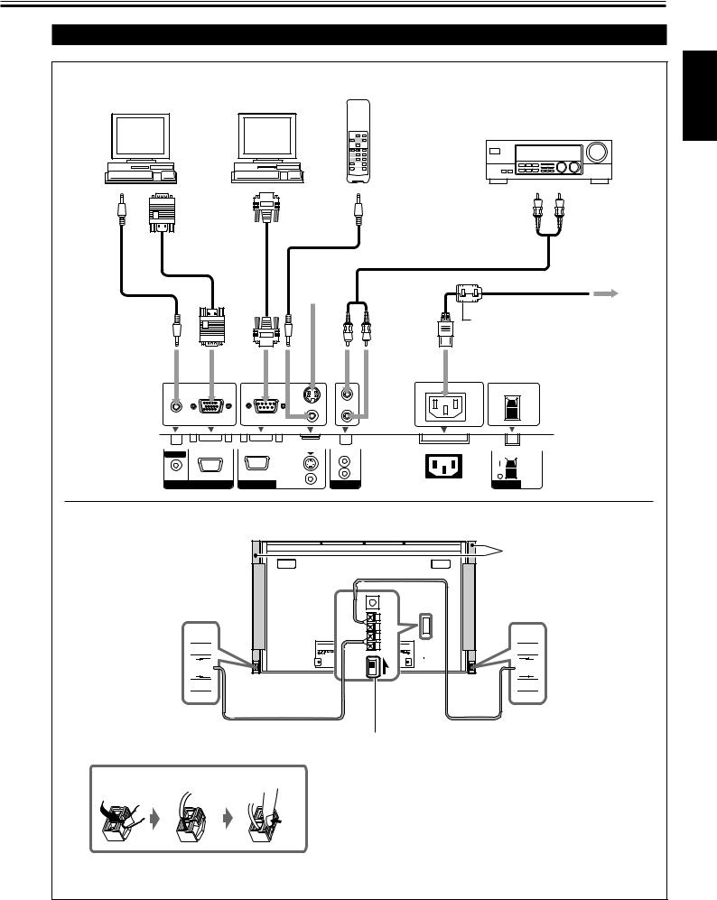
Connection Diagrams
Typical connections
For connection, see page 13.
Personal computer |
|
Personal computer |
|
Remote control |
|
(used as the playback source) |
(used to control the Monitor) |
|
|
||
|
|
|
|
(supplied) |
Amplifier, etc. |
|
|
|
MENU/EXIT |
|
|
|
|
MUTINGVOLUME |
|
|
|
|
|
RGBA |
B |
|
|
|
|
|
VIDEO |
|
|
|
|
.COMPO |
A |
|
|
|
|
INPUTSELECT |
|
|
|
|
|
ASPECT |
DISPLAY |
|
|
|
|
ON |
OFFPOWER |
|
|
To |
To |
To |
|
Cable with stereo |
To |
monitoroutput |
audiooutput |
RS232C- |
|
audioinput |
|
|
mini jacks |
||||
|
|
|
|
|
|
|
|
|
|
(not supplied) |
|
|
|
|
|
|
Power cord (supplied) |
|
|
|
|
|
|
To a wall outlet
Ferrite core (supplied to GM-V42PCE, GM-V42PCEG, and GM-V42S)
• Make sure to attach the ferrite core to the power cord. See also page 8.
AUDIO |
|
|
OUT |
|
|
|
|
|
MAKE |
L |
|
|
|
|
|
|
|
|
||
IN |
RS-232C |
WIRED |
R |
|
|
|
RGB A |
REMOTE |
AUDIO |
AC IN |
POWER |
||
|
External speaker connection
 · ª
· ª


To speaker input terminals
How to connect the cords
External speakers
(Ex. TS-C421SPG)


 · ª
· ª
To speaker input terminals
When using external speakers, set this to EXTERNAL.
Note:
It is recommended to use the speaker unit—TS-C421SPG (not supplied) as the external speakers. You can also connect any speakers of the following specifications:
•Impedance: Between 6 Ω and 8 Ω
•Power handling capacity: More than 3 W
Caution:
•Do not short-circuit the 9 and ( speaker cords each other. (Refer also to the instructions supplied with the speaker unit when connecting speakers.)
ENGLISH
11

Connections (Continued)
AV connections
These terminals are not available for GM-V42PCE, GM-V42PCEG and GM-V42PCEB.
To use them, you need to install video input unit (IF-C42P1G), which is separately purchased.
VCR 1 |
VCR 2 |
DVD player, etc. |
(used as the playback source) |
(used as the playback source) |
(used as the playback source) |
Toaudio output |
Tovideo output |
Toaudio output |
Tovideo output |
ToSvideooutput |
Toaudio output |
Tovideo output |
AUDIO |
VIDEO |
AUDIO |
VIDEO |
|
AUDIO |
|
|
VIDEO |
L/MONO |
|
L/MONO |
|
|
L/MONO |
|
|
|
R IN |
OUT |
R |
IN |
Y/C IN |
R |
Y/G |
Pb/B |
Pr/R HD/Cs VD |
VIDEO A |
|
|
VIDEO B |
|
|
COMPONENT/RGB B |
||
When connecting another PC to the COMPONENT/RGB B terminals, set the “RGB/COMPO.” setting to “RGB” (see page 22).
Personal computer
(used as the playback source)
To audio output |
To G output |
To B output |
To R output |
To HD/Cs output |
To VD output |
Notes:
•You can connect another VCR or Monitor to the VIDEO A OUT terminal. However, when connecting a VCR to the VIDEO A terminals, do not connect both IN and OUT terminals to the same VCR.
•When connecting a VCR to the VIDEO B terminals, you can use either the video or S-video terminals. If the both terminals are used, S-video terminal will have priority.
12
Loading...