

Page 1
Operation and Safety Manual
Original Instructions, Keep this manual with the machine at all times.
ANSI
®
Models
1930ES/2030ES/
2630ES/
2646ES/3246ES
P/N - 3121165
May 1, 2013
Page 2

FOREWORD
3121165 – JLG Lift – a
FOREWORD
IT IS A GOOD PRACTICE TO AVOID PRESSURE-WASHING ELECTRICAL/ELECTRONIC COMPONENTS. SHOULD
PRESSURE-WASHING BE UTILIZED TO WASH AREAS CONTAINING ELECTRICAL/ELECTRONIC COMPONENTS,
JLG INDUSTRIES, INC. RECOMMENDS A MAXIMUM PRESSURE OF 750 PSI (52 BAR) AT A MINIMUM DISTA NC E O F 1 2 IN CH E S ( 3 0. 5 C M ) A WAY F R OM TH E SE COMPONENTS. IF ELECTRICAL/ELECTRONIC COMPONENTS ARE SPRAYED, SPRAYING MUST NOT BE DIRECT AND BE FOR BRIEF TIME PERIODS TO AVOID HEAVY
SATURATION.
This manual is a very important tool! Keep it with the machine at all times.
The purpose of this manual is to provide owners, users, operators, lessors, and lessees with the precautions and
operating procedures essential for the safe and proper machine operation for its intended purpose.
Due to continuous product improvements, JLG Industries, Inc. reserves the right to make specification changes
without prior notification. Contact JLG Industries, Inc. for updated information.
Page 3
FOREWORD
b – JLG Lift – 3121165
SAFETY ALERT SYMBOLS AND SAFETY SIGNAL WORDS
INDICATES AN IMMINENTLY HAZARDOUS SITUATION. IF NOT
AVOIDED, WILL RESULT IN SERIOUS INJURY OR DEATH. THIS DECAL
WILL HAVE A RED BACKGROUND.
INDICATES A POTENTIALITY HAZARDOUS SITUATION. IF NOT
AVOIDED, COULD
RESULT IN SERIOUS INJURY OR DEATH. THIS DECAL
WILL HAVE AN ORANGE BACKGROUND.
INDICATES A POTENTIALITY HAZARDOUS SITUATION. IF NOT
AVOIDED, MAY RESULT IN MINOR OR MODERATE INJURY. IT MAY
ALSO ALERT AGAINST UNSAFE PRACTICES. THIS DECAL WILL HAVE A
YELLOW BACKGROUND.
INDICATES INFORMATION OR A COMPANY POLICY THAT RELATES
DIRECTLY OR INDIRECTLY TO THE SAFETY OF PERSONNEL OR PROTECTION OF PROPERTY.
This is the Safety Alert Symbol. It is used to alert you to the potential personal
injury hazards. Obey all safety messages that follow this symbol to avoid possible injury or death
Page 4
FOREWORD
3121165 – JLG Lift – c
THIS PRODUCT MUST COMPLY WITH ALL SAFETY RELATED BULLETINS. CONTACT JLG INDUSTRIES, INC. OR THE LOCAL AUTHORIZED
JLG REPRESENTATIVE FOR INFORMATION REGARDING SAFETYRELATED BULLETINS WHICH MAY HAVE BEEN ISSUED FOR THIS
PRODUCT.
JLG INDUSTRIES, INC. SENDS SAFETY RELATED BULLETINS TO THE
OWNER OF RECORD OF THIS MACHINE. CONTACT JLG INDUSTRIES,
INC. TO ENSURE THAT THE CURRENT OWNER RECORDS ARE UPDATED
AND ACCURATE.
JLG INDUSTRIES, INC. MUST BE NOTIFIED IMMEDIATELY IN ALL
INSTANCES WHERE JLG PRODUCTS HAVE BEEN INVOLVED IN AN ACCIDENT INVOLVING BODILY INJURY OR DEATH OF PERSONNEL OR
WHEN SUBSTANTIAL DAMAGE HAS OCCURRED TO PERSONAL PROPERTY OR THE JLG PRODUCT.
Contact:
Product Safety and Reliability Department
JLG Industries, Inc.
13224 Fountainhead Plaza
Hagerstown, MD 21742
or Your Local JLG Office
(See addresses on manual rear cover)
In USA:
Toll F re e: 87 7-JL G- SA FE ( 87 7-554 -7 23 3)
Outside USA:
Phone: 240-420-2661
E-mail: ProductSafety@JLG.com
For:
•Accident Reporting
•Product Safety Publications
• Current Owner
Updates
•Questions Regarding
Product Safety
•Standards and Regulations Compliance Information
•Questions Regarding Special Product Applications
•Questions Regarding
Product Modifications
Page 5

FOREWORD
d – JLG Lift – 3121165
REVISION LOG
Original Issue. . . . . . . . . . . . . . . . . . .March 31, 2003
Revised . . . . . . . . . . . . . . . . . . . . . . . .April 30, 2003
Revised . . . . . . . . . . . . . . . . . . . . . . . .May 21, 2003
Revised . . . . . . . . . . . . . . . . . . . . . . . .June 13, 2003
Revised . . . . . . . . . . . . . . . . . . . . . . . .June 25, 2003
Revised . . . . . . . . . . . . . . . . . . . . . . . .August 26, 2003
Revised . . . . . . . . . . . . . . . . . . . . . . . .December 3, 2003
Revised . . . . . . . . . . . . . . . . . . . . . . . .March 3, 2004
Revised . . . . . . . . . . . . . . . . . . . . . . . .September 17, 2004
Revised . . . . . . . . . . . . . . . . . . . . . . . .June 15, 2005
Revised . . . . . . . . . . . . . . . . . . . . . . . .September 12, 2005
Revised . . . . . . . . . . . . . . . . . . . . . . . .October 21, 2005
Revised . . . . . . . . . . . . . . . . . . . . . . . .February 16, 2006
Revised . . . . . . . . . . . . . . . . . . . . . . . .April 11, 2007
Revised . . . . . . . . . . . . . . . . . . . . . . . .February 19, 2010
Revised . . . . . . . . . . . . . . . . . . . . . . . .January 18, 2011
Revised . . . . . . . . . . . . . . . . . . . . . . . .July 13, 2011
Revised . . . . . . . . . . . . . . . . . . . . . . . .September 28, 2012
Revised . . . . . . . . . . . . . . . . . . . . . . . .May 1, 2013
Page 6

TABLE OF CONTENTS
3121165 – JLG Lift – i
SECTION - PARAGRAPH, SUBJECT PAGE SECTION - PARAGRAPH, SUBJECT PAGE
SECTION - 1 - SAFETY PRECAUTIONS
1.1 GENERAL. . . . . . . . . . . . . . . . . . . . . . . . . . . . . . . . . . . . . . . 1-1
1.2 PRE-OPERATION. . . . . . . . . . . . . . . . . . . . . . . . . . . . . . . .1-1
Operator Training and Knowledge . . . . . . . . . . . 1-1
Workplace Inspection . . . . . . . . . . . . . . . . . . . . . . . 1-2
Machine Inspection . . . . . . . . . . . . . . . . . . . . . . . . . 1-3
1.3 OPERATION . . . . . . . . . . . . . . . . . . . . . . . . . . . . . . . . . . . . 1-3
General . . . . . . . . . . . . . . . . . . . . . . . . . . . . . . . . . . . . . 1-3
Trip and Fall Hazards . . . . . . . . . . . . . . . . . . . . . . . . 1-4
Electrocution Hazards . . . . . . . . . . . . . . . . . . . . . . . 1-5
Tipping Hazards. . . . . . . . . . . . . . . . . . . . . . . . . . . . . 1-7
Crushing and Collision Hazards . . . . . . . . . . . . . . 1-8
1.4 TOWING, LIFTING, AND HAULING . . . . . . . . . . . . . . . 1-9
1.5 MAINTENANCE . . . . . . . . . . . . . . . . . . . . . . . . . . . . . . . .1-10
General . . . . . . . . . . . . . . . . . . . . . . . . . . . . . . . . . . . . 1-10
Maintenance Hazards . . . . . . . . . . . . . . . . . . . . . . 1-10
Battery Hazards . . . . . . . . . . . . . . . . . . . . . . . . . . . . 1-11
SECTION - 2 - USER RESPONSIBILITIES, MACHINE PREPARATION & INSPECTION
2.1 PERSONNEL TRAINING. . . . . . . . . . . . . . . . . . . . . . . . . . 2-1
Operator Training . . . . . . . . . . . . . . . . . . . . . . . . . . . 2-1
Training Supervision . . . . . . . . . . . . . . . . . . . . . . . . 2-1
Operator Responsibility . . . . . . . . . . . . . . . . . . . . . 2-1
2.2 PREPARATION, INSPECTION, AND
MAINTENANCE . . . . . . . . . . . . . . . . . . . . . . . . . . . . . . . . .2-2
Pre-Start Inspection. . . . . . . . . . . . . . . . . . . . . . . . . . 2-4
Function Check. . . . . . . . . . . . . . . . . . . . . . . . . . . . . . 2-5
General . . . . . . . . . . . . . . . . . . . . . . . . . . . . . . . . . . . . . 2-8
SECTION - 3 - USER RESPONSIBILITIES AND
MACHINE CONTROLS
3.1 GENERAL . . . . . . . . . . . . . . . . . . . . . . . . . . . . . . . . . . . . . . .3-1
3.2 PERSONNEL TRAINING . . . . . . . . . . . . . . . . . . . . . . . . . .3-1
Operator Training . . . . . . . . . . . . . . . . . . . . . . . . . . . 3-1
Training Supervision. . . . . . . . . . . . . . . . . . . . . . . . . 3-2
Operator Responsibility . . . . . . . . . . . . . . . . . . . . . . 3-2
3.3 OPERATING CHARACTERISTICS AND
LIMITATIONS . . . . . . . . . . . . . . . . . . . . . . . . . . . . . . . . . . .3-2
General . . . . . . . . . . . . . . . . . . . . . . . . . . . . . . . . . . . . . 3-2
Placards . . . . . . . . . . . . . . . . . . . . . . . . . . . . . . . . . . . . . 3-2
Capacities . . . . . . . . . . . . . . . . . . . . . . . . . . . . . . . . . . . 3-2
Stability . . . . . . . . . . . . . . . . . . . . . . . . . . . . . . . . . . . . . 3-3
3.4 CONTROLS AND INDICATORS . . . . . . . . . . . . . . . . . . .3-3
Ground Control Station . . . . . . . . . . . . . . . . . . . . . . 3-3
3.5 PLATFORM CONTROL STATION . . . . . . . . . . . . . . . . .3-5
3.6 MDI (MULTIFUNCTION DIGITAL INDICATOR) . . . . .3-9
MDI Description . . . . . . . . . . . . . . . . . . . . . . . . . . . . 3-10
Page 7

TABLE OF CONTENTS
ii – JLG Lift – 3121165
SECTION - PARAGRAPH, SUBJECT PAGE SECTION - PARAGRAPH, SUBJECT PAGE
SECTION - 4 - MACHINE OPERATION
4.1 DESCRIPTION . . . . . . . . . . . . . . . . . . . . . . . . . . . . . . . . . . .4-1
4.2 OPERATION . . . . . . . . . . . . . . . . . . . . . . . . . . . . . . . . . . . .4-1
Platform/Ground Select Switch . . . . . . . . . . . . . . 4-1
Emergency Stop Switch. . . . . . . . . . . . . . . . . . . . . . 4-1
4.3 RAISING AND LOWERING. . . . . . . . . . . . . . . . . . . . . . . .4-2
Raising . . . . . . . . . . . . . . . . . . . . . . . . . . . . . . . . . . . . . . 4-2
Lowering . . . . . . . . . . . . . . . . . . . . . . . . . . . . . . . . . . . . 4-2
Arm Guards (If equipped) . . . . . . . . . . . . . . . . . . . . 4-3
Platform Extension . . . . . . . . . . . . . . . . . . . . . . . . . . 4-3
Fold-Down Rails . . . . . . . . . . . . . . . . . . . . . . . . . . . . . 4-3
4.4 STEERING. . . . . . . . . . . . . . . . . . . . . . . . . . . . . . . . . . . . . . .4-4
4.5 DRIVING . . . . . . . . . . . . . . . . . . . . . . . . . . . . . . . . . . . . . . . .4-4
Driving Forward . . . . . . . . . . . . . . . . . . . . . . . . . . . . . 4-5
Driving in Reverse . . . . . . . . . . . . . . . . . . . . . . . . . . . 4-5
4.6 PARKING AND STOWING . . . . . . . . . . . . . . . . . . . . . . . .4-7
4.7 BATTERY CHARGING . . . . . . . . . . . . . . . . . . . . . . . . . . . .4-8
Operation . . . . . . . . . . . . . . . . . . . . . . . . . . . . . . . . . . . 4-8
Battery Charger Fault Codes . . . . . . . . . . . . . . . . . 4-9
4.8 PLATFORM LOADING . . . . . . . . . . . . . . . . . . . . . . . . . 4-10
4.9 SAFETY PROP . . . . . . . . . . . . . . . . . . . . . . . . . . . . . . . . . 4-10
4.10 TIE DOWN/LIFT LUGS . . . . . . . . . . . . . . . . . . . . . . . . . 4-11
4.11 LIFTING. . . . . . . . . . . . . . . . . . . . . . . . . . . . . . . . . . . . . . . 4-11
4.12 TOWING. . . . . . . . . . . . . . . . . . . . . . . . . . . . . . . . . . . . . . 4-13
Remote Electric Brake Release. . . . . . . . . . . . . . . 4-13
Push Button Electric Brake Release. . . . . . . . . . 4-13
Mechanical Brake Release . . . . . . . . . . . . . . . . . . 4-14
Mechanical Brake Release . . . . . . . . . . . . . . . . . . 4-15
Mechanical Brake Release . . . . . . . . . . . . . . . . . . 4-16
4.13 DIAGNOSTIC TROUBLE CODES (DTC). . . . . . . . . . . 4-18
Introduction . . . . . . . . . . . . . . . . . . . . . . . . . . . . . . . 4-18
4.14 DTC CHECK TABLES - CONTROL MODULE . . . . . . 4-19
0-0 Help Comments. . . . . . . . . . . . . . . . . . . . . . . . 4-19
2-1 Power-Up . . . . . . . . . . . . . . . . . . . . . . . . . . . . . . 4-21
2-2 Platform Controls . . . . . . . . . . . . . . . . . . . . . . 4-21
2-3 Ground Controls . . . . . . . . . . . . . . . . . . . . . . . 4-23
2-5 Function Prevented . . . . . . . . . . . . . . . . . . . . 4-23
3-1 Line Contactor Open Circuit . . . . . . . . . . . . 4-25
3-2 Line Contactor Short Circuit . . . . . . . . . . . . 4-26
3-3 Ground Output Driver . . . . . . . . . . . . . . . . . . 4-26
4-2 Thermal Limit (SOA) . . . . . . . . . . . . . . . . . . . . 4-29
4-4 Battery Supply . . . . . . . . . . . . . . . . . . . . . . . . . 4-29
6-6 Communication. . . . . . . . . . . . . . . . . . . . . . . . 4-30
6-7 Accessory . . . . . . . . . . . . . . . . . . . . . . . . . . . . . . 4-31
7-7 Electric Motor . . . . . . . . . . . . . . . . . . . . . . . . . . 4-31
8-1 Tilt Sensor . . . . . . . . . . . . . . . . . . . . . . . . . . . . . 4-32
8-2 Platform Load Sense . . . . . . . . . . . . . . . . . . . 4-33
9-9 Hardware . . . . . . . . . . . . . . . . . . . . . . . . . . . . . . 4-33
Page 8

TABLE OF CONTENTS
3121165 – JLG Lift – iii
SECTION - PARAGRAPH, SUBJECT PAGE SECTION - PARAGRAPH, SUBJECT PAGE
SECTION - 5 - EMERGENCY PROCEDURES
5.1 GENERAL. . . . . . . . . . . . . . . . . . . . . . . . . . . . . . . . . . . . . . . 5-1
Emergency Stop Switch . . . . . . . . . . . . . . . . . . . . . 5-1
Manual Descent . . . . . . . . . . . . . . . . . . . . . . . . . . . . . 5-1
5.2 EMERGENCY OPERATION . . . . . . . . . . . . . . . . . . . . . . . 5-2
Operator Unable to Control Machine. . . . . . . . . 5-2
Platform Caught Overhead . . . . . . . . . . . . . . . . . . 5-3
Righting of Tipped Machine . . . . . . . . . . . . . . . . . 5-3
Post-Incident Inspection. . . . . . . . . . . . . . . . . . . . . 5-3
5.3 INCIDENT NOTIFICATION . . . . . . . . . . . . . . . . . . . . . . . 5-3
SECTION - 6 - GENERAL SPECIFICATIONS AND
OPERATOR MAINTENANCE
6.1 INTRODUCTION . . . . . . . . . . . . . . . . . . . . . . . . . . . . . . . .6-1
6.2 OPERATING SPECIFICATIONS . . . . . . . . . . . . . . . . . . . 6-2
Dimensional Data . . . . . . . . . . . . . . . . . . . . . . . . . . . 6-6
Motors . . . . . . . . . . . . . . . . . . . . . . . . . . . . . . . . . . . . . . 6-7
Batteries . . . . . . . . . . . . . . . . . . . . . . . . . . . . . . . . . . . . 6-7
Capacities . . . . . . . . . . . . . . . . . . . . . . . . . . . . . . . . . . 6-8
Tires . . . . . . . . . . . . . . . . . . . . . . . . . . . . . . . . . . . . . . . . 6-8
6.3 CRITICAL STABILITY WEIGHTS . . . . . . . . . . . . . . . . . . .6-9
Lubrication . . . . . . . . . . . . . . . . . . . . . . . . . . . . . . . . 6-10
6.4 OPERATOR MAINTENANCE . . . . . . . . . . . . . . . . . . . .6-11
Oil Check Procedure (1) . . . . . . . . . . . . . . . . . . . . 6-12
Lower (2) & Upper Slide Pads (3) . . . . . . . . . . . . 6-13
6.5 TIRES AND WHEELS . . . . . . . . . . . . . . . . . . . . . . . . . . . 6-15
Tire Wear and Damage. . . . . . . . . . . . . . . . . . . . . . 6-15
Wheel and Tire Replacement . . . . . . . . . . . . . . . . 6-15
Wheel Installation . . . . . . . . . . . . . . . . . . . . . . . . . . 6-15
6.6 SUPPLEMENTAL INFORMATION . . . . . . . . . . . . . . . 6-16
SECTION - 7 - INSPECTION AND REPAIR LOG
Page 9

TABLE OF CONTENTS
iv – JLG Lift – 3121165
SECTION - PARAGRAPH, SUBJECT PAGE SECTION - PARAGRAPH, SUBJECT PAGE
LIST OF FIGURES
2-1. Daily Walk-Around Inspection - Sht. 1 of 3 . . . . . . .2-7
2-2. Daily Walk-Around Inspection - Sht. 2 of 3 . . . . . . .2-8
2-3. Daily Walk-Around Inspection - Sht. 3 of 3 . . . . . . .2-9
2-4. Switch Location - 1 of 2 . . . . . . . . . . . . . . . . . . . . . . . 2-10
2-5. Switch Location - 2 of 2 . . . . . . . . . . . . . . . . . . . . . . . 2-11
3-1. Ground Control Station . . . . . . . . . . . . . . . . . . . . . . . . .3-4
3-2. Battery Charger Status . . . . . . . . . . . . . . . . . . . . . . . . . .3-4
3-3. Platform Control Station . . . . . . . . . . . . . . . . . . . . . . . .3-5
3-4. MDI Indicator - Location and Description . . . . . . . .3-9
3-4. Decal Location - 1930ES- Sht. 1 of 2 . . . . . . . . . . . 3-11
3-5. Decal Location - 1930ES - Sht. 2 of 2 . . . . . . . . . . . 3-12
3-6. Decal Location - 2030ES & 2630ES - Sht. 1 of 2 . 3-13
3-7. Decal Location - 2030ES & 2630ES - Sht. 2 of 2 . 3-14
3-8. Decal Location - 2646ES & 3246ES - Sht. 1 of 2 . 3-15
3-9. Decal Location - 2646ES & 3246ES - Sht. 2 of 2 . 3-16
4-1. Grade and Sideslope. . . . . . . . . . . . . . . . . . . . . . . . . . . .4-6
4-2. Securing Control Station to Platform . . . . . . . . . . . .4-7
4-3. Lifting and Tie Down Diagram . . . . . . . . . . . . . . . . 4-12
4-4. Manual Disengage. . . . . . . . . . . . . . . . . . . . . . . . . . . . 4-14
4-5. Manual Disengage. . . . . . . . . . . . . . . . . . . . . . . . . . . . 4-15
4-6. Manual Disengage. . . . . . . . . . . . . . . . . . . . . . . . . . . . 4-16
4-7. Lifting and Tie Down Chart. . . . . . . . . . . . . . . . . . . . 4-17
6-1. Lubrication Diagram. . . . . . . . . . . . . . . . . . . . . . . . . . 6-11
6-2. Lower Slide Pad Channel. . . . . . . . . . . . . . . . . . . . . . 6-13
6-3. Upper Slide Pad Channel . . . . . . . . . . . . . . . . . . . . . . 6-14
LIST OF TABLES
1-1 Minimum Approach Distances (M.A.D.) . . . . . . . . . 1-6
2-1 Inspection and Maintenance Table . . . . . . . . . . . . . 2-3
2-2 Tilt vs. Height . . . . . . . . . . . . . . . . . . . . . . . . . . . . . . . . . . 2-6
2-3 High Drive Speed Cutout Height. . . . . . . . . . . . . . . . 2-6
3-1 Decal Location Legend . . . . . . . . . . . . . . . . . . . . . . . .3-17
4-1 Battery Charger Flash Codes. . . . . . . . . . . . . . . . . . . . 4-9
6-1 Operating Specifications . . . . . . . . . . . . . . . . . . . . . . . 6-2
6-2 Platform Capacities . . . . . . . . . . . . . . . . . . . . . . . . . . . . 6-5
6-3 Dimensions . . . . . . . . . . . . . . . . . . . . . . . . . . . . . . . . . . . . 6-6
6-4 Battery Specifications . . . . . . . . . . . . . . . . . . . . . . . . . . 6-7
6-5 Capacities. . . . . . . . . . . . . . . . . . . . . . . . . . . . . . . . . . . . . . 6-8
6-6 Tire Specifications. . . . . . . . . . . . . . . . . . . . . . . . . . . . . . 6-8
6-7 Critical Stability Weights. . . . . . . . . . . . . . . . . . . . . . . . 6-9
6-8 Hydraulic Oil Specifications. . . . . . . . . . . . . . . . . . . .6-10
6-9 Wheel Torque Chart . . . . . . . . . . . . . . . . . . . . . . . . . . . 6-16
7-1 Inspection and Repair Log . . . . . . . . . . . . . . . . . . . . . . 7-1
Page 10

SECTION 1 - SAFETY PRECAUTIONS
3121165 – JLG Lift – 1-1
SECTION 1. SAFETY PRECAUTIONS
1.1 GENERAL
This section outlines the necessary precautions for proper and
safe machine usage and maintenance. In order to promote
proper machine usage, it is mandatory that a daily routine is
established based on the content of this manual. A maintenance program, using the information provided in this manual
and the Service and Maintenance Manual, must also be established by a qualified person and must be followed to ensure that
the machine is safe to operate.
The owner/user/operator/lessor/lessee of the machine should
not accept operating responsibility until this manual has been
read, training is accomplished, and operation of the machine
has been completed under the supervision of an experienced
and qualified operator.
These sections contain the responsibilities of the owner, user,
operator, lessor, and lessee concerning safety, training, inspection, maintenance, application, and operation.If there are any
questions with regard to safety, training, inspection, maintenance, application, and operation, please contact JLG Industries,
Inc. (“JLG”).
FAILURE TO COMPLY WIT H T HE SAFE TY PRE CAUTION S LIS TED IN THI S M ANUAL COULD RESULT IN MACHINE DAMAGE, PROPERTY DAMAGE, PERSONAL
INJURY OR DEATH.
Page 11

SECTION 1 - SAFETY PRECAUTIONS
1-2 – JLG Lift – 3121165
1.2 PRE-OPERATION
Operator Training and Knowledge
• The Operators and Safety Manual must be read in its
entirety before operating the machine. For clarification,
questions, or additional information regarding any portions
of this manual, contact JLG Industries, Inc.
• An operator must not accept operating responsibilities
until adequate training has been given by competent and
authorized persons.
• Allow only those authorized and qualified personnel to
operate the machine who have demonstrated that they
understand the safe and proper operation and maintenance of the unit.
• Read, understand, and obey all DANGERS, WARNINGS, CAUTIONS, and operating instructions on the machine and in
this manual.
• Ensure that the machine is to be used in a manner which is
within the scope of its intended application as determined
by JLG.
• All operating personnel must be familiar with the emergency controls and emergency operation of the machine as
specified in this manual.
• Read, understand, and obey all applicable employer, local,
and governmental regulations as they pertain to your utilization and application of the machine.
Workplace Inspection
• Precautions to avoid all hazards in the work area must be
taken by the user before operation of the machine.
• Do not operate or raise the platform from a position on
trucks, trailers, railway cars, floating vessels, scaffolds or
other equipment unless the application is approved in writing by JLG.
• Before operation, check work area for overhead hazards
such as electric lines, bridge cranes, and other potential
overhead obstructions.
• Check floor surfaces for holes, bumps, drop-offs, obstructions, debris, concealed holes, and other potential hazards.
Page 12

SECTION 1 - SAFETY PRECAUTIONS
3121165 – JLG Lift – 1-3
• Check the work area for hazardous locations. Do not oper-
ate the machine in hazardous environments unless
approved for that purpose by JLG.
• Ensure that the ground conditions are adequate to support
the maximum tire load indicated on the tire load decals
located on the chassis adjacent to each wheel.
• Do not operate the machine when wind conditions exceed
28 mph (12.5 m/s).
• This machine can be operated in nominal ambient temperatures of 0
o
F to 104oF (-20oC to 40oC). Consult JLG to opti-
mize operation outside of this temperature range.
Machine Inspection
• Do not operate this machine until the inspections and functional checks have been performed as specified in Section 2
of this manual.
• Do not operate this machine until it has been serviced and
maintained according to the maintenance and inspection
requirements as specified in the machine’s Service and
Maintenance Manual.
• Ensure all safety devices are operating properly. Modification of these devices is a safety violation.
MODIFICATION OR ALTERATION OF AN AERIAL WORK PLATFORM SHALL BE
MADE ONLY WITH PRIOR WRITTEN PERMISSION FROM THE MANUFACTURER.
• Do not operate any machine on which the safety or instruction placards or decals are missing or illegible.
• Check the machine for modifications to original components. Ensure that any modifications have been approved
by JLG.
• Avoid accumulation of debris on platform deck. Keep mud,
oil, grease, and other slippery substances from footwear
and platform deck.
1.3 OPERATION
General
• Do not use the machine for any purpose other than positioning personnel, their tools, and equipment.
• Before operation, the user must be familiar with the
machine capabilities and operating characteristics of all
functions.
• Never operate a malfunctioning machine. If a malfunction
occurs, shut down the machine. Remove the unit from service and notify the proper authorities.
Page 13
SECTION 1 - SAFETY PRECAUTIONS
1-4 – JLG Lift – 3121165
• Do not remove, modify, or disable any safety devices.
• Never slam a control switch or lever through neutral to an
opposite direction. Always return switch to neutral and stop
before moving the switch to the next function. Operate
controls with slow and even pressure.
• Do not allow personnel to tamper with or operate the
machine from the ground with personnel in the platform,
except in an emergency.
• Do not carry materials directly on platform railing unless
approved by JLG.
• When two or more persons are in the platform, the operator
shall be responsible for all machine operations.
• Always ensure that power tools are properly stowed and
never left hanging by their cord from the platform work
area.
• Do not assist a stuck or disabled machine by pushing or
pulling except by pulling at the chassis tie-down lugs.
• Stow scissor arm assembly and shut off all power before
leaving machine.
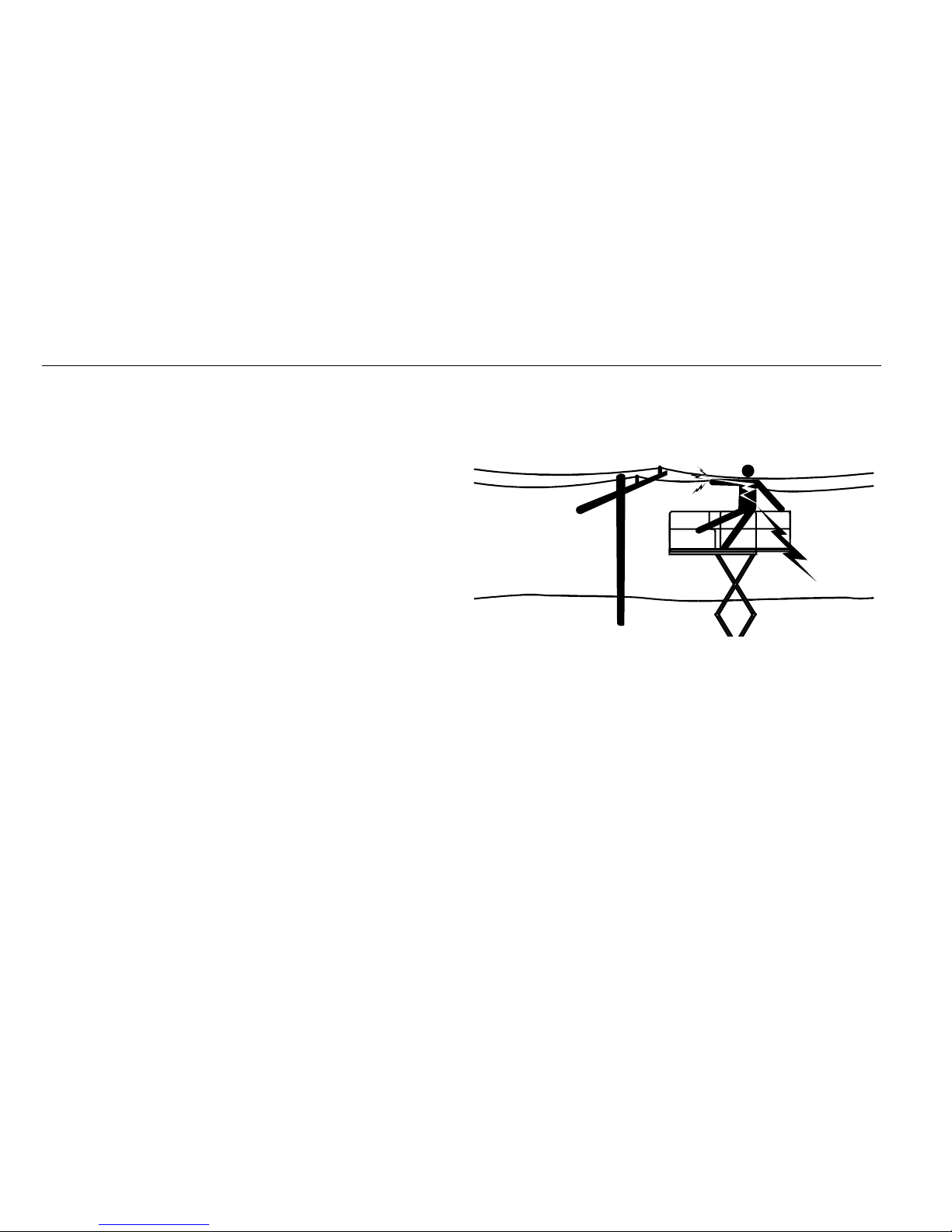
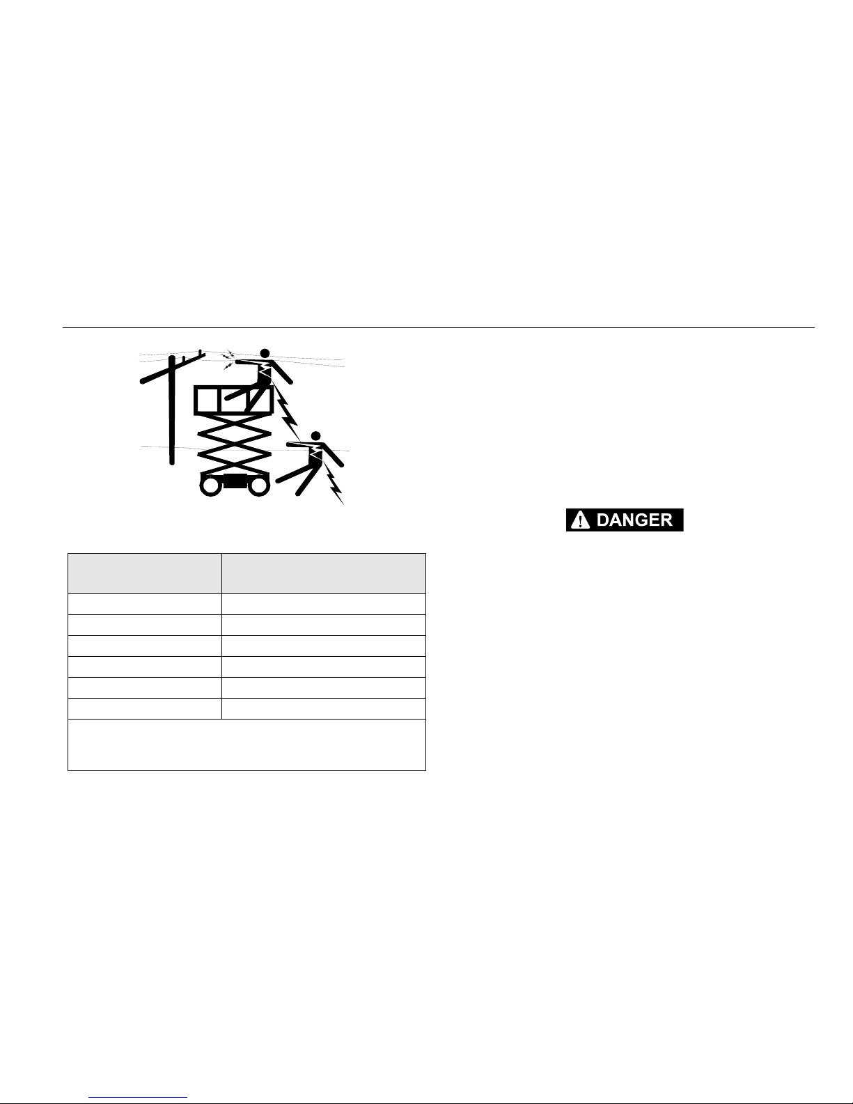
Electrocution Hazards
• This machine is not insulated and does not provide protection from contact or proximity to electrical current.
• Maintain safe clearance from electrical lines, apparatus, or
any energized (exposed or insulated) parts in accordance
with the Minimum Approach Distance (M.A.D.) as specified
in Table 1-1 on page 1-5
• Allow for machine movement and electrical line swaying.
• Maintain a clearance of at least 10 ft (3 m) between any part
of the machine and its occupants, their tools, and their
equipment from any electrical line or apparatus carrying up
to 50,000 volts. One foot additional clearance is required for
every additional 30,000 volts or less.
Page 14
SECTION 1 - SAFETY PRECAUTIONS
3121165 – JLG Lift – 1-5
• The minimum approach distance may be reduced if insulat-
ing barriers are installed to prevent contact, and the barriers are rated for the voltage of the line being guarded.
These barriers shall not be part of (or attached to) the
machine. The minimum approach distance shall be reduced
to a distance within the designed working dimensions of
the insulating barrier. This determination shall be made by
a qualified person in accordance with the employer, local,
or governmental requirements for work practices near
energized equipment.
DO NOT MANEUVER MACHINE OR PERSONNEL INSIDE PROHIBITED ZONE
(M.A.D.). ASSUME ALL ELECTRICAL PA RTS AND WI RIN G A RE EN ERG IZE D
UNLESS KNOWN OTHERWISE.
Tab le 1 -1.M in im um A pp roac h Di sta nc es ( M. A.D. )
Volt age R ange
(Phase to Phase)
MINIMUM APPROACH DISTANCE
in Feet (Meters)
0 to 50KV 10 (3)
Over 50 KV to 200 KV 15 (5)
Over 200 KV to 350 KV 20 (6)
Over 350 KV to 500 KV 25 (8)
Over 500 KV to 750 KV 35 (11)
Over 750 KV to 1000 KV 45 (14)
NOTE: This requirement shall apply except where
employer, local or governmental regulations are
more stringent.
Page 15
SECTION 1 - SAFETY PRECAUTIONS
1-6 – JLG Lift – 3121165
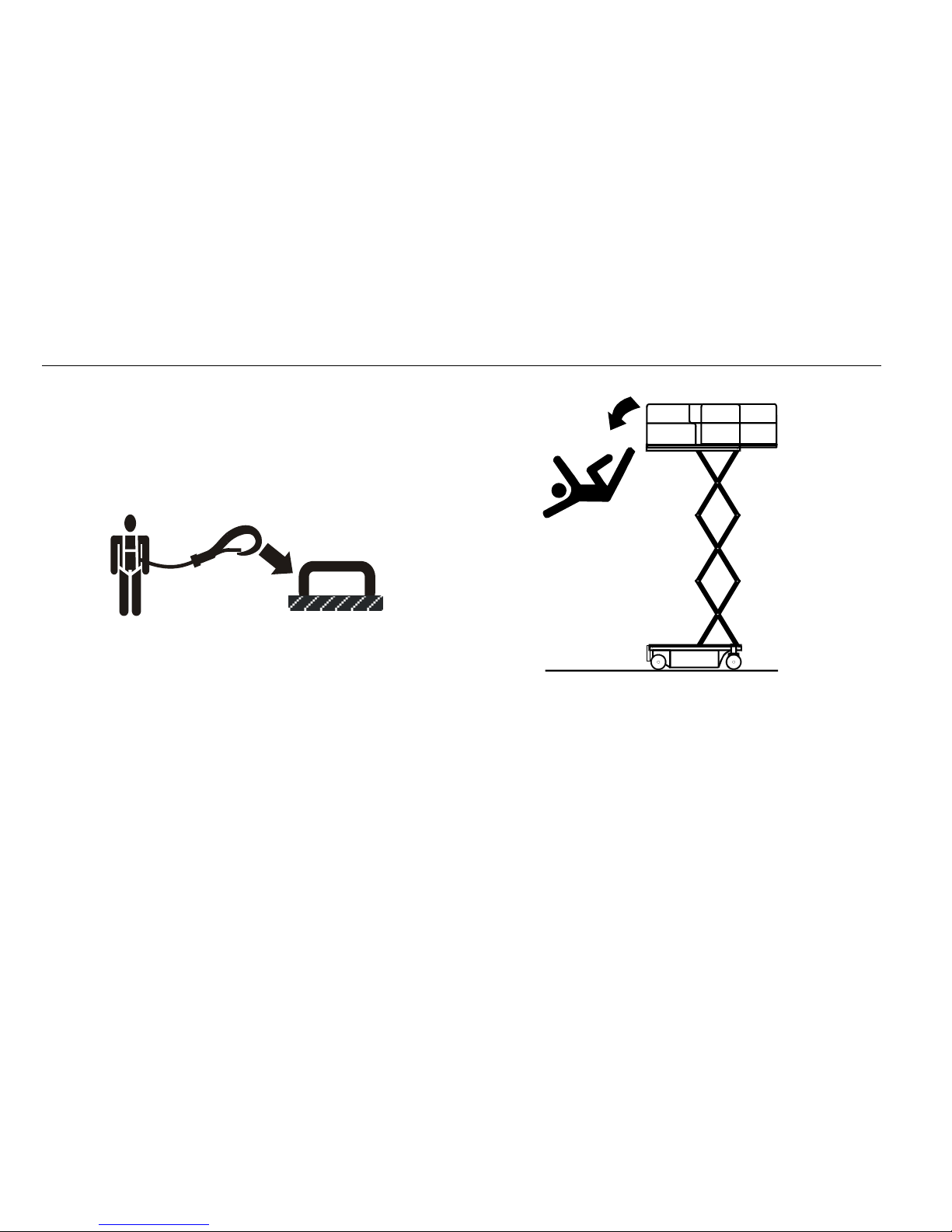
Trip and Fall Hazards
• JLG Industries, Inc. recommends that all persons in the platform wear a full body harness with a lanyard attached to an
authorized lanyard anchorage point while operating this
machine. For further information regarding fall protection
requirements on JLG products, contact JLG Industries, Inc.
• Prior to operation, ensure all gates and rails are fastened
and secured in their proper position. Identify the designated lanyard anchorage point(s) at the platform and
securely attach the lanyard. Attach only one (1) lanyard per
lanyard anchorage point.
• Keep both feet firmly positioned on the platform floor at all
times. Never position ladders, boxes, steps, planks, or similar items on unit to provide additional reach for any purpose.
• Never use the scissor arm assembly to gain access to or
leave the platform.
.
• Use extreme caution when entering or leaving platform.
Ensure that the scissor arm assembly is fully lowered. Face
the machine when entering or leaving the platform. Always
maintain “three point contact” with the machine, using two
hands and one foot or two feet and one hand at all times
during entry and exit.
• Keep oil, mud, and slippery substances cleaned from footwear and the platform floor.
Page 16

SECTION 1 - SAFETY PRECAUTIONS
3121165 – JLG Lift – 1-7
Tipping Hazards
• Ensure that the ground conditions are adequate to support
the maximum tire load indicated on the tire load decals
located on the chassis adjacent to each wheel. Do not travel
on unsupported surfaces.
• The user should be familiar with the driving surface before
driving. Do not exceed the allowable sideslope and grade
while driving.
.
• Do not elevate platform or drive with platform elevated
while on or near a sloping, uneven, or soft surface. Ensure
machine is positioned on a firm, level and smooth surface
before elevating platform or driving with the platform in
the elevated position.
• Before driving on floors, bridges, trucks, and other surfaces,
check allowable capacity of the surfaces.
• Never exceed the maximum work load as specified on the
platform. Keep all loads within the confines of the platform,
unless authorized by JLG.
• Keep the chassis of the machine a minimum of 0.6 m (2 ft)
from holes, bumps, drop-offs, obstructions, debris, concealed holes, and other potential hazards at the ground
level.
• Never attempt to use the machine as a crane. Do not tie-off
machine to any adjacent structure. Never attach wire, cable,
or any similar items to platform.
• Do not cover the platform sides or carry large surface-area
items in the platform when operating outdoors. The addition of such items increases the exposed wind area of the
machine.
• Do not increase the platform size with unauthorized deck
extensions or attachments.
Page 17
SECTION 1 - SAFETY PRECAUTIONS
1-8 – JLG Lift – 3121165
• If scissor arm assembly or platform is caught so that one or
more wheels are off the ground, all persons must be
removed before attempting to free the machine. Use
cranes, forklift trucks, or other appropriate equipment to
stabilize machine and remove personnel.
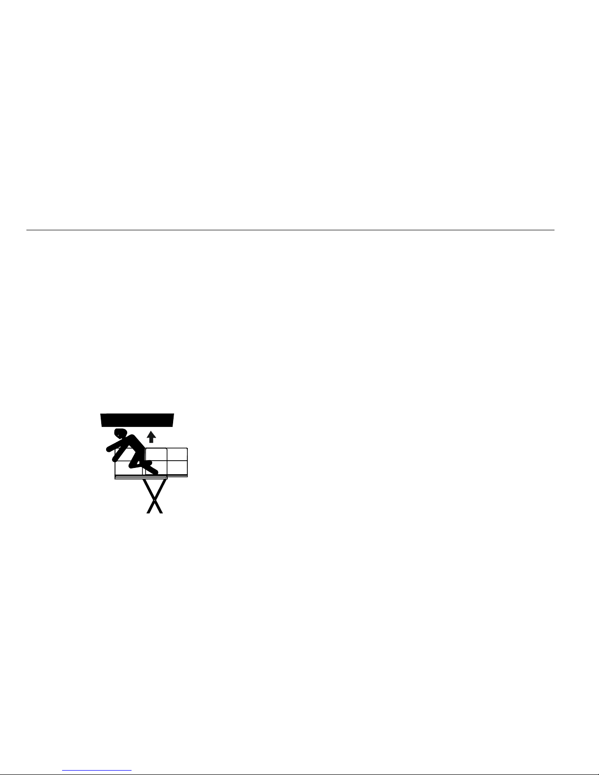
Crushing and Collision Hazards
• Approved head gear must be worn by all operating and
ground personnel.
• Keep hands and limbs out of the scissor arm assembly during operation.
• Watch for obstructions around machine and overhead
when driving. Check clearances above, on sides, and bottom of platform when lifting or lowering platform.
• During operation, keep all body parts inside platform railing.
• Always post a lookout when driving in areas where vision is
obstructed.
• Keep non-operating personnel at least 1.8 m (6 ft) away
from machine during all driving operations.
• Under all travel conditions, the operator must limit travel
speed according to conditions of ground surface, congestion, visibility, slope, location of personnel, and other factors causing hazards of collision or injury to personnel.
• Be aware of stopping distances in all drive speeds. When
driving in high speed, switch to low speed before stopping.
Travel grad es in low spee d only.
• Do not use high speed drive in restricted or close quarters
or when driving in reverse.
• Exercise extreme caution at all times to prevent obstacles
from striking or interfering with operating controls and persons in the platform.
• Ensure that operators of other overhead and floor level
machines are aware of the aerial work platform’s presence.
Disconnect power to overhead cranes. Barricade floor area
if necessary.
• Avoid operating over ground personnel. Warn personnel
not to work, stand, or walk under a raised platform. Position
barricades on floor as necessary.
Page 18

SECTION 1 - SAFETY PRECAUTIONS
3121165 – JLG Lift – 1-9
1.4 TOWING, LIFTING, AND HAULING
• Never allow personnel in platform while towing, lifting, or
hauling.
• This machine should not be towed, except in the event of
emergency, malfunction, power failure, or loading/unloading. Refer to emergency towing procedures.
• Ensure platform is fully retracted and completely empty of
tools prior to towing, lifting or hauling.
• When lifting machine with a forklift, position forks only at
designated areas of the machine. Lift with a forklift of adequate capacity.
• Refer to Section 4 for lifting information.
1.5 MAINTENANCE
General
This section contains general safety precautions which must be
observed during maintenance of this machine. Additional precautions to be observed during machine maintenance are
inserted at the appropriate points in this manual and in the Service and Maintenance Manual. It is of utmost importance that
maintenance personnel pay strict attention to these precautions to avoid possible injury to personnel or damage to the
machine or property. A maintenance program must be established by a qualified person and must be followed to ensure that
the machine is safe.
Maintenance Hazards
• Shut off power to all controls and ensure that all operating
systems are secured from inadvertent motion prior to performing any adjustments or repairs.
• Never work under an elevated platform until it has been
fully lowered to the full down position, if possible, or otherwise supported and restrained from movement with appropriate safety props, blocking, or overhead supports.
• Always relieve hydraulic pressure from all hydraulic circuits
before loosening or removing hydraulic components.
• Always disconnect batteries when servicing electrical components or when performing welding on the machine.
Page 19
SECTION 1 - SAFETY PRECAUTIONS
1-10 – JLG Lift – 3121165
• Shut down the engine (if equipped) while fuel tanks are
being filled.
• Ensure replacement parts or components are identical or
equivalent to original parts or components.
• Never attempt to move heavy parts without the aid of a
mechanical device. Do not allow heavy objects to rest in an
unstable position. Ensure adequate support is provided
when raising components of the machine.
• Remove all rings, watches, and jewelry when performing
any maintenance. Do not wear loose fitting clothing or long
hair unrestrained which may become caught or entangled
in equipment.
• Use only clean approved non-flammable cleaning solvents.
• Never alter, remove, or substitute any items such as coun-
terweights, tires, batteries, platforms or other items that
may reduce or affect the overall weight or stability of the
machine.
• Reference the Service and Maintenance Manual for the
weights of critical stability items.
MODIFICATION OR ALTERATION OF AN AERIAL WORK PLATFORM SHALL BE
MADE ONLY WITH PRIOR WRITTEN PERMISSION FROM THE MANUFACTURER.
Battery Hazards
• Always disconnect batteries when servicing electrical components or when performing welding on the machine.
• Do not allow smoking, open flame, or sparks near battery
during charging or servicing.
• Do not contact tools or other metal objects across the battery terminals.
• Always wear hand, eye, and face protection when servicing
batteries. Ensure that battery acid does not come in contact
with skin or clothing.
BATTERY FLUID IS HIGHLY CORROSIVE. AVOID CONTACT WITH SKIN AND
CLOTHING AT ALL TIMES. IMMEDIATELY RINSE ANY CONTACTED AREA WITH
CLEAN WATER AND SEEK MEDICAL ATTENTION.
• Charge batteries only in a well ventilated area.
• Avoid overfilling the battery fluid level. Add distilled water
to batteries only after the batteries are fully charged.
Page 20

SECTION 2 - USER RESPONSIBILITIES, MACHINE PREPARATION & INSPECTION
3121165 – JLG Lift – 2-1
SECTION 2. USER RESPONSIBILITIES, MACHINE PREPARATION & INSPECTION
2.1 PERSONNEL TRAINING
The aerial platform is a personnel handling device; so it is necessary that it be operated and maintained only by trained personnel.
Persons under the influence of drugs or alcohol or who are
subject to seizures, dizziness or loss of physical control must
not operate this machine.
Operator Training
Operator training must cover:
1. Use and limitations of the controls in the platform and
at the ground, emergency controls and safety systems.
2. Control labels, instructions, and warnings on the
machine.
3. Rules of the employer and government regulations.
4. Use of approved fall protection device.
5. Enough knowledge of the mechanical operation of
the machine to recognize a malfunction or potential
malfunction.
6. The safest means to operate the machine where overhead obstructions, other moving equipment, and
obstacles, depressions, holes, drop-offs.
7. Means to avoid the hazards of unprotected electrical
conductors.
8. Specific job requirements or machine application.
Training Supervision
Train ing mu st be done und er the supervision of a qualified
person in an open area free of obstructions until the trainee
has developed the ability to safely control and operate the
machine.
Operator Responsibility
The operator must be instructed that he/she has the responsibility and authority to shut down the machine in case of a
malfunction or other unsafe condition of either the machine
or the job site.
Page 21
SECTION 2 - USER RESPONSIBILITIES, MACHINE PREPARATION & INSPECTION
2-2 – JLG Lift – 3121165
2.2 PREPARATION, INSPECTION, AND MAINTENANCE
The table below covers the periodic machine inspections and maintenance recommended by JLG Industries, Inc. Consult local regulations for further requirements for aerial work platforms. The frequency of inspections and maintenance must be increased as
necessary when the machine is used in a harsh or hostile environment, if the machine is used with increased frequency, or if the
machine is used in a severe manner.
Tabl e 2- 1. In sp ec ti on a nd M ai nt en an ce Ta bl e
Type Frequency
Primary
Responsibility
Service
Qualification
Reference
Pre-Start Inspection Before using each day; or
whenever there’s an Operator change.
User or Operator User or Operator Operation and Safety Manual
Pre-Delivery Inspection
(see note below)
Before each sale, lease, or rental delivery. Owner, Dealer, or User Qualified JLG
Mechanic
Service and Maintenance Manual and
applicable JLG inspection form
Frequent Inspection In service for 3 months or 150 hours, whichever comes
first; or Out of service for a period of more than 3
months; or Purchased used.
Owner, Dealer, or User Qualified JLG
Mechanic
Service and Maintenance Manual and
applicable JLG inspection form
Annual Machine
Inspection
(see note below)
Annually, no later than 13 months from the date of
prior inspection.
Owner, Dealer, or User Factory Trained
Service Technician
(Recommended)
Service and Maintenance Manual and
applicable JLG inspection form
Preventative Maintenance At intervals as specified in the Service and Mainte-
nance Manual.
Owner, Dealer, or User Qualified JLG
Mechanic
Service and Maintenance Manual
NOTE: Inspection forms are available from JLG. Use the Service and Maintenance Manual to perform inspections.
JLG INDUSTRIES, INC. RECOGNIZES A FACTORY-TRAINED SERVICE TECHNICIAN AS A PERSON WHO HAS SUCCESSFULLY COMPLETED THE JLG SERVICE
TRAI NING SCH OOL FOR THE S PECIFIC JLG PRODU CT MO DEL.
NOTICE
Page 22
SECTION 2 - USER RESPONSIBILITIES, MACHINE PREPARATION & INSPECTION
3121165 – JLG Lift – 2-3
Pre-Start Inspection
The Pre-Start Inspection should include each of the following:
1. Cleanliness – Check all surfaces for leakage (oil, fuel,
or battery fluid) or foreign objects. Report any leakage
to the proper maintenance personnel.
2. Structure - Inspect the machine structure for dents,
damage, weld or parent metal cracks or other discrepancies.
3. Decals and Placards – Check all for cleanliness and
legibility. Make sure none of the decals and placards
are missing. Make sure all illegible decals and placards
are cleaned or replaced.
4. Operation and Safety Manuals – Make sure a copy of
the Operator and Safety Manual, AEM Safety Manual
(ANSI markets only), and ANSI Manual of Responsibili-
ties (ANSI markets only) is enclosed in the weather
resistant storage container.
5. “Walk-Around” Inspection – Refer to Figure 2-1
6. Battery – Charge as required.
7. Fuel (Combustion Engine Powered Machines) – Add
the proper fuel as necessary.
8. Engine Oil Supply (If equipped) - Ensure the engine
oil level is at the full mark on the dipstick and the filler
cap is secure.
9. Fluid Levels – Check the hydraulic oil level. Ensure
hydraulic oil is added as required.
10. Accessories/Attachments - Reference the Operator
and Safety Manual of each attachment or accessory
installed upon the machine for specific inspection,
operation, and maintenance instructions.
11. Function Check – Once the “Walk-Around” Inspection
is complete, perform a functional check of all systems
in an area free of overhead and ground level obstructions. Refer to Section 4 for more specific operating
instructions.
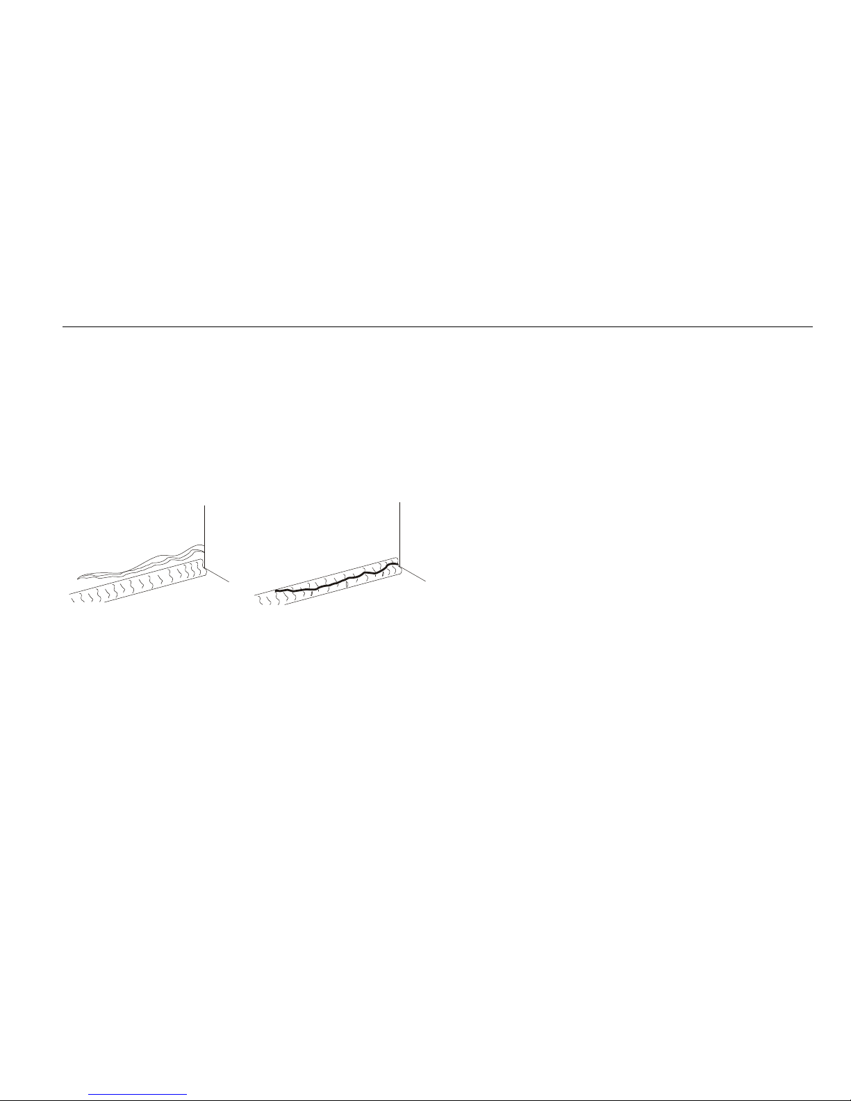
Parent Metal Crack
Wel d Crac k
Page 23

SECTION 2 - USER RESPONSIBILITIES, MACHINE PREPARATION & INSPECTION
2-4 – JLG Lift – 3121165
Function Check
Perform the Function Check as follows:
1. From the ground control console with no load in the
platform:
a. Check that all guards protecting the function con-
trol switches and controllers are in place.
b. Operate all functions and check all limiting and
cutout switches.
c. Check manual descent.
d. Ensure that all machine functions are disabled
when the Emergency Stop Button is depressed.
2. From the platform control console:
a. Ensure that the control console is firmly secured
in the proper location.
b. Check that all guards protecting the function con-
trol switches and controllers are in place.
c. Operate all functions and check all limiting and
cutout switches.
d. Ensure that all machine functions are disabled
when the Emergency Stop Button is depressed.
3. With the platform in the transport (stowed) position:
a. Drive the machine on a grade, not to exceed the
rated gradeability, and stop to ensure the brakes
hold.
b. Check the tilt indicator light to ensure proper
operation. The light should be illuminated when
tilted.
Page 24
SECTION 2 - USER RESPONSIBILITIES, MACHINE PREPARATION & INSPECTION
3121165 – JLG Lift – 2-5
Tabl e 2- 2. Ti lt A ct iv at io n vs. H ei gh t
Model
Tilt Setting
(front to back)
Tilt Setting
(side to side)
Maximum Deck
Elevation
Degrees Feet Meters
1930ES
3
1.5 18.75 (Full) 5.7
2144.3
2.5 11 3.4
3 9 2.7
2030ES
3
1.5 20 (Full) 6
2154.5
2.5 12 3.7
3103
2630ES
3
1.5 25.4 (Full) 7.7
2206
2.5 16 4.9
3134
2646ES
3
226 (Full)7.9
2.5 22 6.7
3206
3246ES
3
231.75 (Full)9.7
2.5 22 6.7
3206
Tabl e 2- 3. Hi gh D ri ve S pe ed C ut ou t He ig ht
Model High Drive Speed Cutout Height
1930ES 54 in. 1.4 m
2030ES 66 in. 1.7 m
2630ES 76 in. 1.9 m
2646ES 76 in. 1.9 m
3246ES 76 in. 1.9 m
Page 25
SECTION 2 - USER RESPONSIBILITIES, MACHINE PREPARATION & INSPECTION
2-6 – JLG Lift – 3121165
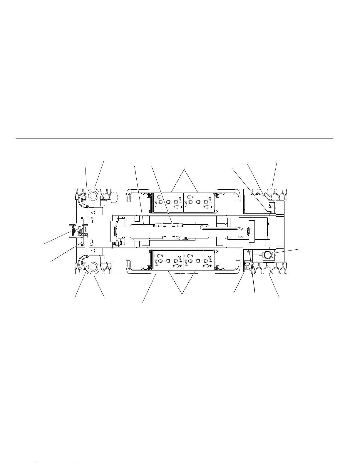
1
9
8
7
6
10
11
12
13
5
14
4
3
4
4
4
6
2
Figure 2-1. Daily Walk-Around Inspection - Sheet 1 of 2
Page 26

SECTION 2 - USER RESPONSIBILITIES, MACHINE PREPARATION & INSPECTION
3121165 – JLG Lift – 2-7
General
Begin the “Walk-Around Inspection” at Item 1, as noted on
the diagram. Continue Left (counterclockwise viewed from
top) checking each item in sequence for the conditions
listed in the following checklist.
TO AVOID POSSIBLE INJURY, BE SURE MACHINE POWER IS “OFF” DURING
“WALK-AROUND INSPECTION”.
NOTICE
DO NOT OVERLOOK VISUAL INSPECTION OF CHASSIS UNDERSIDE. CHECKING THIS AREA OFTEN RESULTS IN DISCOVERY OF CONDITIONS WHICH
COULD CAUSE EXTENSIVE MACHINE DAMAGE.
NOTE: On each item, make sure there are no loose or missing
parts, that they are securely fastened, and that no visible
damage exists in addition to any other criteria mentioned.
1. Platform Control Console - Placard secure and legible,
control lever and switches return to neutral, control lever
lock and emergency stop switch function properly, manual in storage box.
2. Steer Cylinder - See Note
3. Spindle, Tie Rod, Drive Motor and Steer Linkage (left
front) - See Note
4. Wheels and Tires - Properly secured, no missing lug nuts.
Refer to Section 6, Tires and Wheels. Inspect wheels for
damage and corrosion.
5. Pothole Protection System - See Note
6. Battery Compartment - Proper electrolyte level.
7. Proximity Switch - See Note
8. Manual Descent - See Note
9. Beacon - See Note
10. Ground Controls - Placard secure and legible, control
switches return to neutral position, emergency stop
switch functions properly. Control markings legible.
11. Rotary Angle Switch - See Note
12. Hydraulic Pump/Motor, Control Valve Installation - No
unsupported wires or hoses; no damaged or broken
wires - See Note
13. Lift Cylinder - See Note
14. Spindle, Tie Rod, Drive Motor and Steer Linkage (left
front) - See Note
15. Sizzor Arms, Pivot Pins and Sliding Wear Pads (Not
Shown) - See Note
16. Platform/Handrail Installation (Not Shown) - See Note
Figure 2-2. Daily Walk-Around Inspection - Sheet 2 of 2
Page 27
SECTION 2 - USER RESPONSIBILITIES, MACHINE PREPARATION & INSPECTION
2-8 – JLG Lift – 3121165
1
2
SWITCHES THROUGHOUT
MACHINE
NOTE: Item 2 - location for machines prior to S/N’s:
1930ES - USA built - S/N 0200150266
- Belgium built - S/N 1200007882
2030ES/2630ES - USA built - S/N 0200152825
- Belgium built - S/N 1200008481
2646ES/3246ES - USA built - S/N 0200151606
- Belgium built - S/N 1200008265
3
NOTE: Item 1 - location for machines prior to S/N’s:
1930ES - USA built - S/N 0200150266
- Belgium built - S/N 1200007882
2030ES/2630ES - USA built - S/N 0200152825
- Belgium built - S/N 1200008481
2630ES/3246ES - USA built - S/N 0200151610
- Belgium built - S/N 1200008265
1. Pothole Switch - (Typical on
opposite side of machine)
2. Proximity Switch 3. Rotary Angle Switch
Figure 2-3. Switch Location - 1 of 2
Page 28
SECTION 2 - USER RESPONSIBILITIES, MACHINE PREPARATION & INSPECTION
3121165 – JLG Lift – 2-9
1
SWITCHES THROUGHOUT
MACHINE
NOTE: Item 1 - location for machines from S/N’s to present:
1930ES - USA built - S/N 0200151266
- Belgium built - S/N 1200007882
2030ES/2630ES - USA built - S/N 0200152825
- Belgium built - S/N 1200008481
2630ES/3246ES - USA built - S/N 0200151610
- Belgium built - S/N 1200008265
2
Figure 2-5. Switch Location - 2 of 2
1. Pothole Switch (Typical on oppo-
site side of machine)
2. Rotary Angle Switch
Page 29
SECTION 2 - USER RESPONSIBILITIES, MACHINE PREPARATION & INSPECTION
2-10 – JLG Lift – 3121165
NOTES:
Page 30

SECTION 3 - USER RESPONSIBILITIES AND MACHINE CONTROLS
3121165 – JLG Lift – 3-1
SECTION 3. USER RESPONSIBILITIES AND MACHINE CONTROLS
3.1 GENERAL
NOTICE
SINCE THE MANUFACTURER HAS NO DIRECT CONTROL OVER MACHINE APPLICATION AND OPERATION, CONFORMANCE WITH GOOD SAFETY PRACTICES IN
THESE AREAS IS THE RESPONSIBILITY OF THE USER AND HIS OPERATING
PERSONNEL.
This section provides the necessary information needed to
understand control functions. Included in this section are the
operating characteristics and limitations, and functions and purposes of controls and indicators. It is important that the user
read and understand the proper procedures before operating
the machine. These procedures will aid in obtaining optimum
service life and safe operation.
3.2 PERSONNEL TRAINING
The scissor lift is a personnel handling device; therefore, it is
essential that it be operated and maintained only by authorized
personnel who have demonstrated that they understand the
proper use and maintenance of the machine. It is important that
all personnel who are assigned to and responsible for the operation and maintenance of the machine undergo a thorough
training program and check out period in order to become
familiar with the characteristics prior to operating the machine.
Persons under the influence of drugs or alcohol or who are subject to seizures, dizziness or loss of physical control must not be
permitted to operate the machine.
Operator Training
Operator training must include instruction in the following:
1. Use and limitations of the platform controls, ground
controls, emergency controls and safety systems.
2. Knowledge and understanding of this manual and of
the control markings, instructions and warnings on
the machine itself.
3. Knowledge and understanding of all safety work rules
of the employer and of Federal, State and Local Statutes, including training in the recognition and avoidance of potential hazards in the work place; with
particular attention to the work to be performed.
4. Proper use of all required personnel safety equipment.
5. Sufficient knowledge of the mechanical operation of
the machine to recognize a malfunction or potential
malfunction.
Page 31

SECTION 3 - USER RESPONSIBILITIES AND MACHINE CONTROLS
3-2 – JLG Lift – 3121165
6. The safest means to operate near overhead obstruc-
tions, other moving equipment, obstacles, depressions, holes, drop-offs, etc. on the supporting surface.
7. Means to avoid the hazards of unprotected electrical
conductors.
8. Any other requirements of a specific job or machine
application.
Training Supervision
Train ing must be don e under the s upervision o f a qualifi ed
operator or supervisor in an open area free of obstructions until
the trainee has developed the ability to safely control a scissor
lift in congested work locations.
Operator Responsibility
The operator must be instructed that he has the responsibility
and authority to shut down the machine in case of a malfunction or other unsafe condition of either the machine or the job
site and to request further information from his supervisor or
JLG Distributor before proceeding.
NOTE: Manufacturer or Dealer will provide qualified persons for
training assistance with first unit(s) delivered and thereafter as requested by user or his personnel.
3.3 OPERATING CHARACTERISTICS AND LIMITATIONS
General
A thorough knowledge of the operating characteristics and limitations of the machine is always the first requirement for any
user, regardless of user’s experience with similar types of equipment.
Placards
Important points to remember during operation are provided at
the control stations by DANGER, WARNING, CAUTION, IMPORTA NT an d IN STR U CT IO N pl ac a rd s. Th i s i n fo rm at io n i s p la ce d a t
various locations for the express purpose of alerting personnel
of potential hazards constituted by the operating characteristics
and load limitations of the machine. See foreword for definitions of the above placards.
Capacities
Raising platform above horizontal with or without any load in
platform, is based on the following criteria:
1. Machine is positioned on a smooth, firm and level surface.
2. Load is within manufacturer’s rated capacity.
3. All machine systems are functioning properly.
Page 32

SECTION 3 - USER RESPONSIBILITIES AND MACHINE CONTROLS
3121165 – JLG Lift – 3-3
Stability
This machine, as originally manufactured by JLG and operated
within its rated capacity on a smooth, firm and level supporting
surface, provides a stable aerial platform for all platform positions.
3.4 CONTROLS AND INDICATORS
Ground Control Station
DO NOT OPERATE FROM GROUND CONTROL STATION WITH PERSONNEL IN
THE PLATFORM EXCEPT IN AN EMERGENCY.
PERFORM AS MANY PRE-OPERATIONAL CHECKS AND INSPECTIONS FROM
THE GROUND CONTROL STATION AS POSSIBLE.
NOTE: When the machine is shut down for overnight parking or
battery charging, the emergency stop and power select
switches must be positioned to off to prevent draining the
batteries.
1. Platform/Ground Control Switch
A three position, key-operated power select switch
supplies operating power to the platform or ground
controls, as selected. When positioned to platform, the
switch provides power to the emergency stop switch
at the platform controls. When positioned to ground,
the switch provides power to the ground control. The
ground control emergency stop switch provides
power to the key switch. With the power select switch
in the center off position, power is shut off to both
platform and ground controls.
2. Platform Lift/Lower Switch - A three position, momentary contact Lift control switch provides raising and
lowering of the platform when positioned to up or
down.
3. Emergency Stop Switch - A two-position, red, mushroom-shaped emergency stop switch, when positioned to ON with the power selector switch
positioned to ground, furnishes operating power to
the ground control station. In addition, the switch can
be used to turn off power to the function controls in
the event of an emergency. Power is turned on by pulling the switch out (on), and is turned off by depressing
switch.
Page 33

SECTION 3 - USER RESPONSIBILITIES AND MACHINE CONTROLS
3-4 – JLG Lift – 3121165
.
4. Battery Charger Status - This panel, located to the right
of the ground control box, is designed to give the
operator an accurate read on the status of the battery
charger.
a. Green = Charge complete
b. Ye l lo w = C ha r gi ng in p r oc es s
c. Red = Charging abnormal
1
2
3
Figure 3-1. Ground Control Station
GREEN
YELLOW
RED
Figure 3-2. Battery Charger Status
Page 34

SECTION 3 - USER RESPONSIBILITIES AND MACHINE CONTROLS
3121165 – JLG Lift – 3-5
3.5 PLATFORM CONTROL STATION
1
2
4
5
6
7
89
10
11
12
13
NOTE: *There is no light equipped on a single
capacity ANSI machine.
1. Indoor (CE) / Zone A Capacity (ANSI)*
2. Outdoor (CE) / Zone B Capacity (ANSI)
3. System Distress
4. Battery Discharge Indicator
5. Tilt Indicator
6. Overload Indicator
7. Capacity Selec t Switch
8. Lift/Drive Select Switch
9. Horn
10. Steer Switch
11. Contro ller
12. Emergency Stop Switch
13. Tr ig ge r Sw it ch
Figure 3-3. Platform Control Station
Page 35

SECTION 3 - USER RESPONSIBILITIES AND MACHINE CONTROLS
3-6 – JLG Lift – 3121165
NOTE: The platform control indicator panel uses different shaped
symbols to alert the operator to different types of operational situations that could arise. The meaning of those
symbols are explained below.
1. Indoor (CE) / Zone A Capacity (ANSI/AUS) - This indicator light will be illuminated when the Indoor (CE) or
Zone A (ANSI/AUS) capacity is selected.
2. Outdoor (CE) / Zone B Capacity (ANSI/AUS) - This indicator light will be illuminated when the Outdoor (CE)
or Zone B (ANSI/AUS) capacity is selected.
3. System Distress Indicator - This indicator will light up
with a fault flash code that will determine where a
problem, within the system, exists.
4. Battery Discharge Indicator (BDI) - This set of lights is
designed to let the operator know the condition of
the batteries.
5. Tilt Indicator Warning Light - A red warning light on
the control panel that illuminates when the chassis is
on a slope greater than what the machine is programmed for.
6. Overload Indicator (If Equipped) - Indicates the platform has been overloaded. An audible alarm will also
signal when the platform is overloaded.
NOTE: If the Overload Indicator is illuminated, all functions will
be prevented from the platform controls. Using the
ground controls or manual descent, fully lower the
machine and reduce the weight in the platform so as to
not exceed the rated workload indicated on the capacity
decal.
7. Capacity Select Switch - On model 2630ES/3246ES
machines this switch is used to choose allowable
capacity zone. On all CE machines, except the 2630ES,
this switch is used to select either indoor or outdoor
capacity zone.
Indicates a potentially hazardous situation, which if
not corrected, could result in serious injury or death.
This indicator will be red.
Indicates an abnormal operating condition, which if
not corrected, may result in machine interruption or
damage. This indicator will be yellow.
Indicates important information regarding the operating condition, i.e. procedures essential for safe operation. This indicator will be green with the exception of
the capacity indicator which will be green or yellow
depending upon platform position.
Page 36

SECTION 3 - USER RESPONSIBILITIES AND MACHINE CONTROLS
3121165 – JLG Lift – 3-7
8. Lift/Drive Select - This toggle switch is used to select
either drive or lift. After selecting a function, the controller must be moved in the proper direction in order
to activate that function. The function must be
selected with the joystick in the neutral position. Otherwise, the function select will not occur.
9. Horn - This push-button switch, when activated, permits the operator to warn jobsite personnel when the
machine is operating in the area.
10. Steer Switch - The steer switch is a thumb operated
switch located at the top of the control handle.
Depressing the switch to the right will steer the
wheels to the right. Depressing the switch to the left
will steer the wheels to the left.
11. Controller - The control handle controls three functions: drive, lift, and steer. The drive and lift switch
must be selected prior to moving the control handle.
After selecting the drive function, moving the control
handle forward will drive the machine forward and
moving the control handle backwards will drive the
machine backward. After selecting the lift function,
moving the control handle backward will raise the
platform and moving the control handle forward will
lower the platform. The speed on all selected functions is proportionally controlled by the distance of
travel of the hand controller. The thumb-operated
steer switch on top of the hand controller activates the
steer wheels in the direction activated (right or left).
12. Emergency Stop Switch - A two-position, red, mushroom-shaped emergency stop switch functions to
provide power to the platform control station and also
to turn off power to the platform function controls in
the event of an emergency. With the power selector
switch positioned to platform, power is turned on by
pulling the switch out (on), and is turned off by pushing the switch in (off).
13. Trigg er Switch - This switch is loc ated on t he front of
the controller. The trigger switch acts as an enable and
must be depressed when operating the drive, steer
and lift functions. When released, the function being
operated will stop.
IF THE TILT INDICATOR WARNING LIGHT OR HORN IS ON WHEN PLATFORM IS
RAISED, LOWER PLATFORM COMPLETELY, THEN REPOSITION MACHINE SO
THAT IT IS LEVEL BEFORE RAISING PLATFORM.
14. Tilt Alarm Warning Horn - The Tilt Alarm Warning Horn
is activated when the chassis is on a slope greater than
what the machine is programmed for and the platform is elevated.
Page 37

SECTION 3 - USER RESPONSIBILITIES AND MACHINE CONTROLS
3-8 – JLG Lift – 3121165
NOTE: ANSI/CSA/AUS machines are equipped with a tilt interlock
which cuts out drive and lift up functions when chassis is
on a slope greater than what is allowable for the machine
and the platform is elevated.
DO NOT “LOWER” WITHOUT COMPLETELY RETRACTING THE PLATFORM
EXTENSION.
DO NOT OPERATE MACHINE IF HIGH DRIVE SPEED OPERATES WHEN PLATFORM IS RAISED ABOVE THE STOWED POSITION.
Page 38

SECTION 3 - USER RESPONSIBILITIES AND MACHINE CONTROLS
3121165 – JLG Lift – 3-9
3.6 MDI (MULTIFUNCTION DIGITAL INDICATOR)
1
2
4
5
5
5
5
3
1. Battery Compartment
2. Diagnostic Trouble Code LCD
3. Wrench Icon ( Fault)
4. Faul t LE D
5. Battery Discharge Indicator (BDI)
Figure 3-3. MDI Indicator - Location and Description
Page 39

SECTION 3 - USER RESPONSIBILITIES AND MACHINE CONTROLS
3-10 – JLG Lift – 3121165
MDI Description
Located in the battery compartment on the left side of the
machine (See Figure 3-3.) is a Multifunction Digital Indicator
(MDI). The purpose of the MDI is to display Diagnostic Trouble
Codes (DTC) when a functional problem occurs with the
machine. The MDI is plugged into the diagnostic connector in
the battery compartment.
When a problem occurs:
1. A Wrench Icon will display on the Diagnostic Trouble
Code LCD display.
2. A three to five digit DTC will display on the Diagnostic
Trouble Code LC D display, belo w the w rench ico n.
NOTE: When more than one DTC exists, each DTC will be dis-
played on the LCD for 3 seconds before changing to the
next DTC. Once the last active DTC is displayed, the display
will recycle indefinitely until the DTC’s are corrected.
3. The red Fault LED will illuminate (this does not apply
to 00x
DTC’s; the Fault LED will not illuminate for these
DTC’s).
NOTE: For DTC’s and desc ription s, r efer to Sect ion 4.13, Diagnos-
tic Trouble Codes (DTC) Check Tables.
Also located on the MDI are Battery Discharge Indicators (BDI).
These green LEDs indicate the level of charge in the batteries.
NOTE: When the batteries are completely discharged, the LED in
the 0-25% range "red area" will flash.
• The BDI will convey the same information as the BDI on the
platform control station. (see Figure 3-3., Platform Control
Station)
• Under normal driving conditions the BDI’s will be illuminated. When a DTC exists (other than 00x
DTC’s) the BDI
LEDs will not be illuminated.
100%
75%
50%
0-25%
Battery Charge/Discharge Indicator
Page 40

SECTION 3 - USER RESPONSIBILITIES AND MACHINE CONTROLS
3121165 – JLG Lift – 3-11
16
9
35
22
41
15
44
40
21
18
36
7
4
30
19
45
22
36
14
40
21
27
41
22 12
29
32
Both
Sides
Both
Sides
42
46
47
Figure 3-3. Decal Location - 1930ES- Sheet 1 of 2
Page 41

SECTION 3 - USER RESPONSIBILITIES AND MACHINE CONTROLS
3-12 – JLG Lift – 3121165
17
16
17
13
11
14
15
11
22
41
21
40
30
36
14
22
4127
47
21
40
31
45 19
2630
24
46
4
25
23
36
10
Both
Sides
43
38
Figure 3-4. Decal Location - 1930ES - Sheet 2 of 2
Page 42

SECTION 3 - USER RESPONSIBILITIES AND MACHINE CONTROLS
3121165 – JLG Lift – 3-13
14
40
21
27
41 22
12
29
32
36
Both
Sides
Both
Sides
41
22
15
44
21
40
36
15
14
18
35
42
16
Both
Sides
Both
Sides
26
46
24
38
19
25
23
30
4
47
Figure 3-5. Decal Location - 2030ES & 2630ES - Sheet 1 of 2
Page 43

SECTION 3 - USER RESPONSIBILITIES AND MACHINE CONTROLS
3-14 – JLG Lift – 3121165
46
22
19
4
30
30
40
21
27
41 22
14
10
16
134317
17
11
41
11
22
21
40
30
9
7
47
Figure 3-6. Decal Location - 2030ES & 2630ES - Sheet 2 of 2
Page 44

SECTION 3 - USER RESPONSIBILITIES AND MACHINE CONTROLS
3121165 – JLG Lift – 3-15
4
26
30
23
25
19
46
24 24
43
19
25
23
30
46
26
4
16
35
21
40
44
15
41
22
32
29
Both Sides
42
18
36
14
15
12 38
36
14
40
21 41
22
Both Sides
Both Sides
Both
Sides
47
Figure 3-7. Decal Location - 2646ES & 3246ES - Sheet 1 of 2
Page 45

SECTION 3 - USER RESPONSIBILITIES AND MACHINE CONTROLS
3-16 – JLG Lift – 3121165
7
4
22
46
30
19
30
27
Both Sides
10
30
40
21
41
22
11
30
17
13
16
9
47
Figure 3-8. Decal Location - 2646ES & 3246ES - Sheet 2 of 2
Page 46

SECTION 3 - USER RESPONSIBILITIES AND MACHINE CONTROLS
3121165 – JLG Lift – 3-17
Tabl e 3- 1. De ca l Lo ca ti on L eg en d
Item
ANSI
0275220-3
CE
0275221-3
Australian
0275222-3
English/French
0275223-3
English/
Spanish
0275224-3
Portuguese/
Spanish
0275225-3
English/
Chinese
0275226-3
Korean
0275227-3
1 - 3 N/A N/A N/A N/A N/A N/A N/A N/A
417005841700584170058417005841700584170058417005841700584
5 - 6 N/A N/A N/A N/A N/A N/A N/A N/A
717026311702631170263117026311702631170263117026311702631
8N/A N/A N/A N/A N/A N/A N/A N/A
917044121704412170441217044121704412170441217044121704412
10 1705693 1705693 1705693 1705693 1705693 1705693 1705693 1705693
11 1704016 1704016 1704016 1704016 1703817 1703817 1704016 1704016
12 1702155 1702155 1702155 1702155 1702155 1702155 1702155 1702155
13 1701509 1701509 1701509 1701509 1701509 1701509 1701509 1701509
14 1703811 1703811 1703811 1703811 1703811 1703811 1703811 1703811
15 1703814 1703814 1703814 1703814 1703814 1703814 1703814 1703814
16 1704277 1704277 1704277 1704277 1704277 1704277 1704277 1704277
17 1703819 1703819 1703819 1703819 1703819 1703819 1703819 1703819
18 1703822 1703822 1703822 1703822 1703822 1703822 1703822 1703822
Page 47

SECTION 3 - USER RESPONSIBILITIES AND MACHINE CONTROLS
3-18 – JLG Lift – 3121165
19 1705692 1705692 1705692 1705692 1705692 1705692 1705692 1705692
20 N/A N/A N/A N/A N/A N/A N/A N/A
21 1705694 1705673 1705673 1705694 1705694 1705722 1705694 1705694
22 1705695 1705671 1705671 1705695 1705695 1703834 1705695 1705695
23 1705686 N/A N/A 1705723 1705720 17057 26 1705946 1706057
24 1705680 N/A N/A 1705680 1705680 17058 94 1705680 1705680
25 1705679 N/A N/A 1705679 1705679 17057 27 1705679 1705679
26 1705681 N/A N/A 1705681 1705681 17057 21 1705681 1705681
27 1703813 1705670 1705670 1704340 1704339 1704341 1704344 1707022
28 N/A N/A N/A N/A N/A N/A N/A N/A
29
(1930ES)
(2030ES)
(2630ES)
(2646ES)
(3246ES)
1705642
1705643
1705644
1705645
1705646
1705642
1705643
1705644
1705645
1705646
1705642
1705643
1705644
1705645
1705646
1705642
1705643
1705644
1705645
1705646
1705642
1705643
1705644
1705645
1705646
1705642
1705643
1705644
1705645
1705646
1705642
1705643
1705644
1705645
1705646
1705642
1705643
1705644
1705645
1705646
Tabl e 3- 1. De ca l Lo ca ti on L eg en d
Item
ANSI
0275220-3
CE
0275221-3
Australian
0275222-3
English/French
0275223-3
English/
Spanish
0275224-3
Portuguese/
Spanish
0275225-3
English/
Chinese
0275226-3
Korean
0275227-3
Page 48

SECTION 3 - USER RESPONSIBILITIES AND MACHINE CONTROLS
3121165 – JLG Lift – 3-19
30
(1930ES)
(2030ES)
(2630ES)
(2646ES)
(3246ES)
1705638
1705639
1705941
1705640
1705641
1705666
1705667
1705942
1705668
1705704
1705666
1705667
1705887
1705668
1705819
1705638
1705639
1705941
1705640
1705641
1705638
1705639
1705941
1705640
1705641
1705638
1705639
1705941
1705640
1705641
1705638
1705639
1705941
1705640
1705641
1705638
1705639
1705941
1705640
1705641
31 1705699 N/A N/A N/A N/A N/A 1705699 N/A
32 0272870 0272870 0272870 0272870 0272870 0272870 0272870 0272870
33 - 34 N/A N/A N/A N/A N/A N/A N/A N/A
35 0272870 0272870 0272870 0272870 0272870 0272870 0272870 0272870
36
(1930ES)
(2030ES)
(2630ES)
(2646ES)
(3246ES)
1705647
1704134
1706310
1706311
1706311
1705648
1706310
1706310
1706312
1706312
1705648
1706310
1706310
1706312
1706312
1705647
1704134
1706310
1706311
1706311
1705647
1704134
1706310
1706311
1706311
1705647
1704134
1706310
1706311
1706311
1705647
1704134
1706310
1706311
1706311
1705647
1704134
1706310
1706311
1706311
37 N/A N/A N/A N/A N/A N/A N/A N/A
38 N/A N/A N/A 1705303 N/A 1705303 N/A N/A
Tabl e 3- 1. De ca l Lo ca ti on L eg en d
Item
ANSI
0275220-3
CE
0275221-3
Australian
0275222-3
English/French
0275223-3
English/
Spanish
0275224-3
Portuguese/
Spanish
0275225-3
English/
Chinese
0275226-3
Korean
0275227-3
Page 49

SECTION 3 - USER RESPONSIBILITIES AND MACHINE CONTROLS
3-20 – JLG Lift – 3121165
39 N/A N/A N/A N/A N/A N/A N/A 3251243
40 N/A N/A N/A 1705717 1705725 1705725 1705943 1706052
41 N/A N/A N/A 1705718 1705724 1705724 1705944 1706056
42
(1930ES)
(2030ES)
(2630ES)
(2646ES)
(3246ES)
1705850
1705850
1705850
1705851
1705851
1705850
1705850
1705850
1705851
1705851
1705850
1705850
1705850
1705851
1705851
1705850
1705850
1705850
1705851
1705851
1705850
1705850
1705850
1705851
1705851
1705850
1705850
1705850
1705851
1705851
1705850
1705850
1705850
1705851
1705851
1705850
1705850
1705850
1705851
1705851
43 N/A N/A N/A 3252098 1705719 1705719 1705945 1706053
44 1701499 1701499 1701499 1701499 1701499 1701499 1701499 1701499
45
(1930ES) 1001092071 1001092497 1001092071 1001092580 1001092071 1001092071 1001092071 1001092071
46 1001094359 1001094359 1001094359 1001094359 1001094359 1001094359 1001094359 1001094359
47 1001146794 1001146795 1001146795 1001146794 1001146794 1001146794 1001146794 1001146794
Tabl e 3- 1. De ca l Lo ca ti on L eg en d
Item
ANSI
0275220-3
CE
0275221-3
Australian
0275222-3
English/French
0275223-3
English/
Spanish
0275224-3
Portuguese/
Spanish
0275225-3
English/
Chinese
0275226-3
Korean
0275227-3
Page 50

SECTION 4 - MACHINE OPERATION
3121165 – JLG Lift – 4-1
SECTION 4. MACHINE OPERATION
4.1 DESCRIPTION
This machine is a self-propelled aerial work platform on top of
an elevating ‘scissor’ mechanism. The Scissor Lift’s intended purpose is to position personnel with their tools and supplies at
positions above ground level. The machine can be used to reach
work areas located above machinery or equipment positioned
at ground level.
The JLG Scissor Lift has a primary operator Control Station in the
platform. From this Control Station, the operator can drive and
steer the machine in both forward and reverse directions, raise
and lower the platform and, if equipped, operate the powered
deck extension. The machine has a Ground Control Station
which will override the Platform Control Station. Ground Controls operate lift up and down. Ground Controls are to be used
only in an emergency to lower the platform to the ground
should the operator in the platform be unable to do so.
NOTE: All platform extension capacities are 250 lb (120 kg).
4.2 OPERATION
Platform/Ground Select Switch
The power selector switch functions to direct electrical power to
the desired control station. With the switch in the ground position, power is supplied to the emergency stop switch at the
ground control station. When the switch is in the platform position, power is supplied to the emergency stop switch at the
platform control station. The switch should be in the off position
when parking the machine overnight.
Emergency Stop Switch
This switch, when in the on (out) position, provides electrical
power to the ground controls or platform controls, as applicable. In addition, the switch can be used to turn off power (push
the switch IN) to the function controls in the event of an emergency.
Page 51

SECTION 4 - MACHINE OPERATION
4-2 – JLG Lift – 3121165
4.3 PLATFORM OPERATION
ONLY RAISE PLATFORM ON A FIRM, LEVEL AND SMOOTH SURFACE FREE OF
OBSTRUCTIONS AND HOLES.
NOTE: When selecting between the Lift/Drive functions, the con-
troller must be in the neutral position for 3 seconds before
the function change is effective. The machine is inopera-
ble at this point.
Raising
1. If the machine is shut down, place the power selector
switch to the desired position (platform or ground).
2. Position the applicable emergency stop switch to the
"ON" position.
NOTE: If the machine is equipped with a footswitch (Japanese
Specification Only), the footswitch must be depressed in
conjunction with the red trigger switch, located on the
controller. Power is removed from the platform controls
when the footswitch is released.
3. If operating from the ground controls, position the lift
switch to up and hold until desired elevation is
achieved. If operating from the platform controls,
select lift function, squeeze and hold the red trigger
switch, move the controller backward (up) and hold
until desired elevation is reached. The lift switch works
in conjunction with the enable switch. Releasing the
trigger switch will stop the function being operated.
Lowering
ENSURE SCISSOR ARM AREA IS FREE OF PERSONNEL PRIOR TO LOWERING
PLATFORM.
NOTE: The machine is equipped with a descent alarm which will
sound as the platform is being lowered (CE Optional).
If operating from the ground controls, position the lift switch to
down and hold until desired elevation is achieved or until platform is fully lowered.
If operating from the platform controls, select lift function
squeeze the red trigger switch and push the controller forward
(down) and hold until desired elevation is reached or until platform is fully lowered. The lift switch works in conjunction with
the enable switch. Releasing the trigger switch will stop the
function being operated.
Page 52

SECTION 4 - MACHINE OPERATION
3121165 – JLG Lift – 4-3
Arm Guards (If equipped)
If the machine is equipped with arm guards, the platform will
stop lowering and an alarm will sound once it has reached a preset height. At this point, the trigger switch and controller must
be released before the lowering function can begin again.
DO NOT ‘LOWER’ WITHOUT COMPLETELY RETRACTING THE PLATFORM
EXTENSION.
Platform Extension
The machine is equipped with a mechanically extendable deck,
giving the operator better access to worksites. On the 1930ES/
2030ES/2630ES this extension adds 3 ft (0.9 m) and on the
2646ES and 3246ES the extension adds 4 ft (1.2 m) to the front
of the platform. To extend the deck, pull out handles from latch
and swing up, then use the handles and handrail to push the
extendable deck out. To retract the deck, pull out the handles
from latch and swing up, use the handles and handrail to pull
and retract the deck. Be sure the handles are in place after the
deck is retracted. Maximum capacity of the deck extension is
250 lbs (120 kg).
Page 53

SECTION 4 - MACHINE OPERATION
4-4 – JLG Lift – 3121165
Fold-Down Rails
DO NOT RAISE PLATFORM WITH RAILS FOLDED DOWN. THE RAILS MUST BE
IN THE UPRIGHT POSITION AND PROPERLY PINNED WHEN RAISING THE
PLATFORM.
NOTE: The rails must only be folded down when the machine is in
the stowed (fully lowered) position.
NOTE: Ensure that the drywall gate at the rear of the machine is
up and locked in position.
Platform control box should be removed and placed on
the platform with rails folded down.
1. To f ol d do wn t he r ai ls , rem ov e th e fo ur ( 4) b ai l pi ns a t
the two front corners and center of the rails.
2. Tak in g a firm h ol d o n th e to p rail s, car ef ully p ush fo rward and lower until the top rail rests on the middle
rail.
3. To r ai se t he r ai ls b ac k to the upright position, firmly
pull the rails toward the back of the machine and
replace the bail pins into the rails. Return drywall gate
to the lowered position.
AFTER THE RAILS HAVE BEEN FOLDED DOWN, USE EXTREME CAUTION WHEN
EXITING AND ENTERING THE PLATFORM.
BAIL PI NS
Page 54

SECTION 4 - MACHINE OPERATION
3121165 – JLG Lift – 4-5
4.4 STEERING
To st ee r t he ma ch in e, the th um b operated steer control switch
on the controller handle is positioned to the right for traveling
right, or to the left for traveling left. When released, the switch
will return to the center-off position and the wheels will remain
in the previously selected position. To return the wheels to the
straightened position, the switch must be activated in the
opposite direction until the wheels are centered.
4.5 DRIVING
DO NOT DRIVE WITH PLATFORM RAISED EXCEPT ON A SMOOTH, FIRM AND
LEVEL SURFACE FREE OF OBSTRUCTIONS AND HOLES.
TO AVOID LOSS OF TRAVEL CONTROL OR UPSET ON GRADES AND SIDESLOPES,
DO NOT DRIVE MACHINE ON GRADES OR SIDESLOPES EXCEEDING THOSE
SPECIFIED. REFERENCE FIGURE 4-1., GRADE AND SIDESLOPE.
Driving Forward
1. Place power selector switch at ground control station
to "Platform."
2. Position emergency stop switch at platform control
station to "On" position.
3. Select "Drive" on the drive/lift select switch.
4. Squeeze controller (joystick), depressing red trigger
on front of joystick, and move joystick forward for
duration of travel. The drive system is proportional so
for additional drive speed, push the joystick further in
the direction of travel. Releasing the trigger will stop
the function being operated.
Driving in Reverse
1. Position power selector switch at ground control station to "Platform."
2. Position emergency stop switch at platform control
station to "On" position.
3. Squeeze joystick, depressing red trigger on front of
joystick, and move joystick backward (reverse) for
duration of travel. The drive system is proportional so
for additional drive speed, push the joystick further in
the direction of travel. Releasing the trigger will stop
the function being operated.
Page 55

SECTION 4 - MACHINE OPERATION
4-6 – JLG Lift – 3121165
S
I
D
E
S
L
O
P
E
HORIZONTAL
G
R
A
D
E
Figure 4-1. Grade and Sideslope
Page 56

SECTION 4 - MACHINE OPERATION
3121165 – JLG Lift – 4-7
4.6 PARKING AND STOWING
Park and stow the machine as follows:
1. Drive the machine to a reasonably well-protected and
well-ventilated area.
2. Ensure the platform is fully lowered.
3. Position the emergency stop switch to the "Off " posi-
tion.
4. If necessary, cover the instruction placards, caution
and warning decals so that they will be protected from
hostile environment.
5. Chock at least two wheels when parking the machine
for an extended period of time.
6. Turn the p ower selector switch to "Off " and remove
the key to disable the machine and prevent unauthorized use. The platform control station can also be
secured to it’s mounting plate, see Figure 4-2.
7. If equipped with the optional anti-vandal package, the
platform and ground control box assemblies may be
covered and locked to prevent access.
NOTICE
DO NOT OPERATE MACHINE FROM THE PLATFORM OR GROUND CONTROLS
WITH THE ANTI-VANDAL COVERS CLOSED AND LOCKED IN PLACE.
NOTE: If machine is not equipped with the anti-vandal covers
option to prevent unauthorized removal, the platform
control station can be secured to it’s mount by placing a
lock through one or more of the holes located on it’s upper
mounting tabs.
Figure 4-2. Securing Control Station to Platform
Page 57

SECTION 4 - MACHINE OPERATION
4-8 – JLG Lift – 3121165
4.7 BATTERY CHARGING
Operation
NOTE: Be sure that machine is parked in a well ventilated area
before charging begins.
ONLY PLUG THE CHARGER INTO A PROPERLY INSTALLED AND GROUNDED
OUTLET. DO NOT USE GROUND ADAPTORS OR MODIFY PLUG. DO NOT TOUCH
NON-INSULATED PORTION OF OUTPUT CONNECTOR OR NON-INSULATED BATTERY TERMINAL.
ALWAYS DISCONNECT THE AC SUPPLY BEFORE MAKING OR BREAKING THE
CONNECTIONS TO THE BATTERY BEFORE CHARGING.
DO NOT OPEN OR DISASSEMBLE CHARGER.
DO NOT OPERATE CHARGER IF THE AC SUPPLY CORD IS DAMAGED OR IF THE
CHARGER HAS RECEIVED A SHARP BLOW, BEEN DROPPED, OR OTHERWISE
DAMAGED IN ANY WAY.
The battery charger receptacle is located at the right rear of the
machine near the ground control panel.
1. Connect the charger to a grounded outlet.
2. On the Battery Charger, the charger will automatically
turn on and go through a short LED indicator self-test.
All LED’s will flash in an up and down sequence for two
seconds.
3. The batteries are fully charged when green light on
the battery charger status panel is illuminated.
Page 58

SECTION 4 - MACHINE OPERATION
3121165 – JLG Lift – 4-9
NOTE: If the charger is left plugged in, the charger will automati-
cally restart a complete charge cycle if the batteries voltage drops below a minimum voltage or 30 days has
elapsed.
Battery Charger Fault Codes
If a fault occurred during charging, the red "Fault" LED will flash
with a code. The number of flashes corresponds to the error.
Refer to Table 4-1, Battery Charger Flash Codes.
Tabl e 4- 1. Ba tt er y Ch ar ge r Fl as h Co de s
Flash(s) Fault Faul t Remo val
1Battery voltage highAuto-recover - Indicates a high battery pack voltage
2Battery voltage lowAuto-recover - Indicates either a battery pack failure, battery pack not connected to charger or battery volts per cell is less than 0.5 VDC.
Check the battery pack and connections
3Charge time-out Indicates the batteries did not charge in the allowed time. This could occur if the batteries are a larger capacity than the algorithm is
intended for or if the batteries are damaged old or in poor condition.
4Check battery Indicates the batteries could not be trickle charged up to the minimum voltage per cell level required for the charge to be started.
5Over-temperatureAuto-recover - Indicates charger has shut down due to high internal temperature
6QuiQ fault Indicates that the battery will not accept charge current, or an internal fault has been detected in the charger. This fault will nearly always
be set within the first 30 seconds of operation. Once it has been determined that the batteries and connections are not faulty and fault 6 is
again displayed after interrupting AC power for at least 10 seconds, the charger must be brought to a qualified service depot.
Page 59

SECTION 4 - MACHINE OPERATION
4-10 – JLG Lift – 3121165
4.8 PLATFORM LOADING
The platform maximum rated load capacity is shown on a placard located on the platform and is based upon the following criteria:
1. The machine is positioned on a firm, uniform surface.
2. All braking devices are engaged.
3. Refer to Section 6 for the maximum platform capacity.
NOTE: It is important to remember that the load should be
evenly distributed on the platform. The load should be
placed near the center of the platform when possible.
4.9 SAFETY PROP
THE SAFETY PROP MUST BE USED WHENEVER MAINTENANCE PERFORMED
ON THE MACHINE REQUIRES THE SCISSOR ARMS TO BE RAISED AND ONLY
WITH NO LOAD IN THE PLATFORM.
To en ga ge th e s af et y p ro p, rais e t he pl at fo rm , s wi ng th e s af et y
prop from it’s stowed position located on the right side of the
machine. Lower the platform until the safety prop rests on the
designated safety prop rest.
To s to re t he s af et y pro p, r ai se t he p la tform , sw in g th e sa fety
prop around and restore it back to its stowed position.
Page 60

SECTION 4 - MACHINE OPERATION
3121165 – JLG Lift – 4-11
4.10 TIE DOWN/LIFT LUGS
When transporting the machine, the platform extension must
be fully retracted and the platform fully lowered in the stowed
mode with the machine securely tied down to the truck or
trailer deck. There are two tie-down/lift lugs located at the rear
of the machine for lifting and tieing down. There is a single tiedown lug at the front of the machine. This lug is designed for
tieing down only. Do not attempt to lift machine from the front
lug.
LIFTING THE MACHINE FROM THE SIDES USING A FORK TRUCK IS NOT RECOMMENDED BY JLG. IN THE EVENT THAT THE MACHINE NEEDS TO BE LIFTED
FROM THE SIDES CAUTION MUST BE USED TO AVOID JAMMING THE POT HOLE
PROTECTION BARS UP AGAINST THE FRAME.
EVERY TIME THE MACHINE IS LIFTED FORM THE SIDE, BE SURE AND TEST THE
POT HOLE PROTECTION SYSTEM BEFORE THE MACHINE IS PUT BACK INTO
OPERATION.
4.11 LIFTING
In the event that the machine must be lifted, there is a forktruck
pocket located at the rear of the machine. The machine can also
be lifted using a proper spreader bar and straps/chains. Reference Figure 4-3., Lifting and Tie Down Diagram.
Page 61

SECTION 4 - MACHINE OPERATION
4-12 – JLG Lift – 3121165
R
R
FRONT
(JAPAN - AUS)
(ANSI - CSA - CE)
FRONT
REAR
Figure 4-3. Lifting and Tie Down Diagram
Page 62

SECTION 4 - MACHINE OPERATION
3121165 – JLG Lift – 4-13
4.12 TOWING
It is not recommended that this machine be towed, except in
the event of an emergency such as a machine malfunction or a
total machine power failure.
NOTE: The machine may be equipped with a remote electric
brake release, a push button electric brake release, or both
styles of electric brake release.
RUNAWAY VEHICLE/MACHINE HAZARD. MACHINE HAS NO TOWING BRAKES,
TOWING VEHICLE MUST BE ABLE TO CONTROL MACHINE AT ALL TIMES. ONHIGHWAY TOWING NOT PERMITTED. FAILURE TO FOLLOW INSTRUCTIONS
COULD CAUSE SERIOUS INJURY OR DEATH.
MAXIMUM TOWING SPEED 5 MPH (8 KPH) FOR NO FURTHER THAN 60 FEET
(18 M).
MAXIMUM TOWING GRADE 25%.
Remote Electric Brake Release
1. Chock wheels or secure machine with tow vehicle.
2. Pull the emergency stop switch out and position the
keyswitch to ground mode.
3. The brake release cable hangs on a hook in the battery
compartment on the opposite side of the ground control panel.
4. Locate brake release plug near the analyzer plug at the
left front corner of the machine and plug the release
cable into the plug.
5. Depress switch to release brakes.
6. When finished towing; release switch, unplug release
switch and return brake switch to the proper storage
area in the battery compartment.
Push Button Electric Brake Release
NOTE: The push button electric brake release is located on the
right side of the machine just forward of the ground control box.
1. Chock wheels or secure machine with tow vehicle.
2. Pull the emergency stop switch out and position the
keyswitch to ground mode.
3. Push the button once to release the brakes.
4. To re se t th e br ak es , pu sh t he button again, or push in
the emergency stop switch, or take the ground control
keyswitch out of the ground mode position.
Page 63

SECTION 4 - MACHINE OPERATION
4-14 – JLG Lift – 3121165
Mechanical Brake Release
Machines, USA built prior to s/n 0200118041:
Machines, Belgium built prior to s/n 1200001487:
1. Chock wheels or secure machine with tow vehicle.
2. Power machine in ground mode.
3. Remove the three cover bolts (1), from the back of drive
motor unit.
4. Remove brake cover (2).
5. Locate the 2 disengage bolts (3) that are stored in the
motor end cap. Remove bolts and insert them into the two
disengage holes (4) in the brake housing, see Item 4 in
Figure 4-4., Manual Disengage.
6. Tighten down the bolts and the brake on that drive motor
will disengage.
7. Repeat this procedure on opposite wheel drive. With both
drive motor brakes now disengaged, the machine can be
moved manually.
8. After towing is complete, chock wheels and remove 2 disengage bolts (3) from disengage holes (4). Insert bolts
back into original holes in motor end cap.
9. Reinstall cover (2).
AFTER THE MACHINE IS TOWED, THE DISENGAGE BOLTS MUST BE REMOVED
FROM THE BRAKE DISENGAGE HOLES. THE BRAKES CANNOT BE ENGAGED
WITH THE DISENGAGE BOLTS IN THE BRAKE DISENGAGE HOLES. THIS WILL
CAUSE THE MACHINE TO ROLL WHEN PARKED ON AN INCLINE.
Figure 4-4. Manual Disengage
Page 64

SECTION 4 - MACHINE OPERATION
3121165 – JLG Lift – 4-15
Mechanical Brake Release
Machines, USA built s/n 0200152825 to s/n 0200170585:
Machines, Belgium built s/n 1200008481 to s/n 1200015159:
1. Chock wheels or secure machine with tow vehicle.
2. Power machine in ground mode.
3. Remove the two cover bolts (1), cover (2), and cover o-
ring seal (3) from the back of drive motor unit.
4. Insert the cover bolts (1) into the two disengage holes in
the brake housing (4), see Item 4 in Figure 4-5., Manual
Disengage.
5. Tighten down the bolts and the brake on that drive motor
will disengage.
6. Repeat this procedure on opposite wheel drive. With both
drive motor brakes now disengaged, the machine can be
moved manually.
7. After towing is complete, chock wheels and remove cover
bolts (1) from disengage holes (4).
8. Reinstall cover (2). Before installation, check the cover oring seal (3) for damage, replace if necessary.
AFTER THE MACHINE IS TOWED, THE DISENGAGE BOLTS MUST BE REMOVED
FROM THE BRAKE DISENGAGE HOLES. THE BRAKES CANNOT BE ENGAGED
WITH THE DISENGAGE BOLTS IN THE BRAKE DISENGAGE HOLES. THIS WILL
CAUSE THE MACHINE TO ROLL WHEN PARKED ON AN INCLINE.
Mechanical Brake Release
Machines, USA built s/n 0200170585 to Present:
Machines, Belgium built s/n 1200015159 to Present:
Figure 4-5. Manual Disengage
Page 65

SECTION 4 - MACHINE OPERATION
4-16 – JLG Lift – 3121165
1. Chock wheels or secure machine with tow vehicle.
2. Ensure E-stop button is pushed in to the "OFF" posi-
tion.
3. Remove the two cover bolts (2) and brake cover (1).
4. Insert the cover bolts (2) into the two disengage
holes (3) in the brake housing, see item 3 in Figure 4-
6., Manual Disengage.
5. Tighten down the cover bolts (2) and the brake on
that drive motor will disengage.
6. Repeat this procedure on opposite wheel drive. With
both drive motor brakes now disengaged, the
machine can be moved manually.
7. After towing is complete, chock wheels and remove
cover bolts (2) from disengage holes (3).
8. Reinstall brake cover (1).
AFTER THE MACHINE IS TOWED, THE DISENGAGE BOLTS MUST BE REMOVED
FROM THE BRAKE DISENGAGE HOLES. THE BRAKES CANNOT BE ENGAGED
WITH THE DISENGAGE BOLTS IN THE BRAKE DISENGAGE HOLES. THIS WILL
CAUSE THE MACHINE TO ROLL WHEN PARKED ON AN INCLINE.
Figure 4-6. Manual Disengage
Page 66

SECTION 4 - MACHINE OPERATION
3121165 – JLG Lift – 4-17
X
Z
MODEL
1930ES
2030ES
2630ES
2646ES
3246ES
WHEELBASE
(in.)X(in.)Z(in.)
MODEL
2030ES
2630ES
2646ES
3246ES
WHEELBASE
(cm.)X(cm.)Z(cm.)
1930ES
33
83.7
160
52
52
33
33
108.6
108.4
209.1
209.1
187.7
187.7
98.9
38.5
13
33.5 63
20.5
43.8
82.32
20.5
43.8
13
13
82.32
73.9
73.9
38.5
97.8
Figure 4-7. Lifting and Tie Down Chart
Page 67

SECTION 4 - MACHINE OPERATION
4-18 – JLG Lift – 3121165
4.13 DIAGNOSTIC TROUBLE CODES (DTC)
Introduction
This sub-section provides a reference for Diagnostic Trouble Codes (DTC) read from the Multifunction Digital Indicator (MDI). For
more information on the MDI, refer to Section 3. For information on the locations of any limit switches/sensors, refer to Section 2.
DTCs are sorted in groups by the first two digits, which is also the system distress lamp flash code. To troubleshoot multiple DTCs,
start with the DTC with the higher first two digits. If a correction is made during a check, conclude the check by cycling the
machine power, using the emergency stop switch.
Page 68

SECTION 4 - MACHINE OPERATION
3121165 – JLG Lift – 4-19
4.14 DIAGNOSTIC TROUBLE CODES (DTC) CHECK TABLES
0-0 Help Comments
DTC FAULT ME SSAG E DESCRIPTION CHECK
Error (Displayed on MDI) The MDI is powered, but cannot communi-
cate with the control system.
• Check the MDI connector.
• Check the diagnostic connector.
Refer problem to a qualified JLG mechanic.
001 EVERYTHING OK The normal help message in platform
mode. Displays on the analyzer only.
002 GROUND MODE OK The normal help message in ground mode.
Displays on the analyzer only.
003 ALARM SOUNDING - TILTED & ABOVE
ELEVATION
Control sys tem sens es that the platform is
elevated and the vehicle is tilted, and the
machine not configured to cutout.
• Check that the machine is tilted. If so, lower the platform and reposition
the machine to a level surface.
• Fully stow the platform.
• The tilt sensor is par t of the ground control box. Check that the ground
control box is secured to the machine.
• Check that the pothole protection switches are securely mounted.
• Check that the elevation angle sensor is securely mounted.
Refer problem to a qualified JLG mechanic.
Page 69

SECTION 4 - MACHINE OPERATION
4-20 – JLG Lift – 3121165
004 DRIVING AT CUTBACK - ABOVE ELEVA-
TION
The platform is elevated and the machine
is driving.
• Fully stow the platform.
• Check that the elevation angle sensor is securely mounted.
• Check that the pothole protection switches are securely mounted.
Refer problem to a qualified JLG mechanic.
005 DRIVE & LIFT UP PREVENTED - TILTED
& ELEVATED
Driving is not possible since the platform is
elevated and the chassis is not level.
• Check that the machine is tilted. If so, lower the platform and reposition
the machine to a level surface.
• Fully stow the platform.
• The tilt sensor is part of the ground control box. Check that the ground
control box is secured to the machine.
• Check that the pothole protection switches are securely mounted.
• Check that the elevation angle sensor is securely mounted.
Refer problem to a qualified JLG mechanic.
006 LIFT UP PREVENTED - MAX HEIGHT
ZONE A
The vehicle has reached the maximum
height and further lift up motion is not
possible. Applicable to 2630ES or 3246ES.
• Check that the zone is set appropriately for the platform load.
• Check that the platform height is at the rated maximum height specifica-
tion (20’ for 2630 or 26’ for the 3246).
• Check that the elevation angle sensor is securely mounted.
• If there are any elevation sensor faults (DTC 251, 252, 2511, or 2512),
troubleshoot those first.
Refer problem to a qualified JLG mechanic.
0-0 Help Comments
DTC FAULT ME SSAG E DESCRIPTION CHECK
Page 70

SECTION 4 - MACHINE OPERATION
3121165 – JLG Lift – 4-21
007 DRIVING AT CUTBACK - POTHOLE STILL
ENGAGED
While stowed, drive speed is reduced since
the control system detected that the pothole protection mechanism failed to
retract.
• Check for obstructions around the pot-hole protection mechanisms.
• Check that the PHP switches are securely mounted.
Refer problem to a qualified JLG mechanic.
008 FUNCTIONS LOCKED OUT - SYSTEM
POWERED DOWN
After 2 hours with out activity, the control
system enters a low-power state to preserve battery charge.
• Normal operation should resume after power is cycled off then back on.
• Check batteries charge, condition, etc.
Refer problem to a qualified JLG mechanic.
009 DRIVE PREVENTED - ELEVATED ABOVE
DRIVE CUTOUT HEIGHT
The platform is elevated above the calibrated cutout height.
• Check that the elevation angle sensor is securely mounted.
Refer problem to a qualified JLG mechanic.
2-1 Power-Up
DTC FAULT ME SSAG E DESCRIPTION CHECK
211 POWER CYCLE This help message is issued at each power
cycle. Displays on the analyzer only.
Normal operation. No check necessary.
212 KEYSWITCH FAULTY Both platform and ground modes are
selected simultaneously. Defaults to
ground mode.
Refer problem to a qualified JLG mechanic.
0-0 Help Comments
DTC FAULT ME SSAG E DESCRIPTION CHECK
Page 71

SECTION 4 - MACHINE OPERATION
4-22 – JLG Lift – 3121165
2-2 Platform Controls
DTC FAULT ME SSAG E DESCRIPTION CHECK
221 FUNCTION PROBLEM - HORN PERMA-
NENTLY SELECTED
The horn switch was closed during power up in platform mode.
• Check if the horn switch is damaged, obstructed or jammed.
Refer problem to a qualified JLG mechanic.
222 FUNCTION PROBLEM - INDOOR / OUT-
DOOR PERMANENTLY SELECTED
The indoor / outdoor (zone A / zone B)
switch was closed during power-up in platform mode.
• Check if the indoor/outdoor (zone A / zone B) capacity switch is damaged,
obstructed or jammed.
Refer problem to a qualified JLG mechanic.
223 FUNCTION PROBLEM - DRIVE & LIFT
ACTI VE TOGETHER
The drive and lift inputs are closed simultaneously in platform mode.
• Check drive/lift switch for visible damage.
Refer problem to a qualified JLG mechanic.
224 FUNCTION PROBLEM - STEER LEFT
PERMANENTLY SELECTED
The steer left switch was closed during
power-up in platform mode.
• Check if the steer left switch is obstructed or jammed.
Refer problem to a qualified JLG mechanic.
225 FUNCTION PROBLEM - STEER RIGHT
PERMANENTLY SELECTED
The steer right switch was closed during
power-up in platform mode.
• Check if the steer right switch is obstructed or jammed.
Refer problem to a qualified JLG mechanic.
226 ACCELERATOR FAULTY - WIPER OUT OF
RANGE
There is a problem with the joystick. • Cent er joyst ick and check to see if a power cycle will c lear DTC.
Refer problem to a qualified JLG mechanic.
227 STEER SWITCHES FAULTY The steer left and steer right inputs were
closed simultaneously.
• Check if the steer switches are damaged, obstructed or jammed.
Refer problem to a qualified JLG mechanic.
228 FUNCTION LOCKED OUT - ACCELERA-
TOR NOT C ENTE RED
The joystick was not centered at power-up. • Release joystick and allow to center.
• Check if the joystick is obstructed or jammed.
Refer problem to a qualified JLG mechanic.
229 FUNCTION PROBLEM - TRIGGER PER-
MANENTLY CLOSED
The trigger switch was closed during
power-up in platform mode.
• Check if the trigger switch is obstructed or jammed.
Refer problem to a qualified JLG mechanic.
Page 72

SECTION 4 - MACHINE OPERATION
3121165 – JLG Lift – 4-23
2210 TRIGGER CLOSED TOO LONG WHILE IN
NEUTRAL
The trigger switch was closed for more
than five seconds while the joystick was
centered.
• Check if the trigger switch is obstructed or jammed.
Refer problem to a qualified JLG mechanic.
2232 FUNCTION PROBLEM - DRIVE & LIFT
BOTH OPEN
The drive and li ft inputs are both de-energized in platform mode.
• Check if either function is active, if Yes;
Refer problem to a qualified JLG mechanic.
2-3 Ground Controls
DTC FAULT ME SSAG E DESCRIPTION CHECK
231 FUNCTION PROBLEM - LIFT PERMA-
NENTLY SELECTED
The ground control box lift switch was
closed up or down, during power-up in
ground mode.
• Check if the lift switch is obstructed or jammed.
Refer problem to a qualified JLG mechanic.
232 GROUND LIFT UP / DOWN ACTIVE
TOGE THER
The lift up / down inputs are closed simultaneously.
• Check if the lift switch is obstructed or jammed.
Refer problem to a qualified JLG mechanic.
233 FUNCTION PROBLEM - BRAKE RELEASE
PERMANENTLY SELECTED
The manual brake release switch was
closed during power-up.
• Check if the brake release switch is obstructed or jammed.
Refer problem to a qualified JLG mechanic.
2-2 Platform Controls
DTC FAULT ME SSAG E DESCRIPTION CHECK
Page 73

SECTION 4 - MACHINE OPERATION
4-24 – JLG Lift – 3121165
2-5 Function Prevented
DTC FAULT ME SSAG E DESCRIPTION CHECK
251 ELEV ANGLE SENSOR FAULTY - VOLT-
AGE O UT OF RANG E
There is a problem with the elevation
angle sensor input.
• Check that the platform elevation sensor is securely mounted and
undamaged.
Refer problem to a qualified JLG mechanic.
252 ELEV ANGLE SENSOR HAS NOT BEEN
CALIBRATED
The elevation angle sensor has not been
calibrated.
Refer problem to a qualified JLG mechanic.
253 DRIVE PREVENTED - CHARGER CON-
NECTED
Driving is not possible while the vehicle is
charging.
• Check if the charger is connected to off board power source and disconnect if desired.
Refer problem to a qualified JLG mechanic.
254 DRIVE & LIFT UP PREVENTED - CHAR-
GER CONNECTED
Drive or lift is not possible while the vehicle
is charging AND is configured to prevent all
motion.
• Check if the charger is connected to off board power source and disconnect if desired.
Refer problem to a qualified JLG mechanic.
255 PLATFORM OVERLOADED The load sensing system measured plat-
form load is excessive.
• Remove excess weight from the platform.
• Check that the platform is not caught on something, preventing up or
down movement.
Refer problem to a qualified JLG mechanic.
256 DRIVE PREVENTED - POTHOLE NOT
ENGAGED
Driving is not possible while elevated since
the pot-hole protection system failed to
deploy.
• Check for obstructions or mechanical problems around the pot-hole protection mechanisms.
• Check that the PHP switches are securely mounted.
Refer problem to a qualified JLG mechanic.
Page 74

SECTION 4 - MACHINE OPERATION
3121165 – JLG Lift – 4-25
257 ELEV PROX PERMANENTLY CLOSED -
CHECK PROX AND ANGLE ADJUSTMENT
The elevation proximity switch shows the
platform to be stowed, while the elevation
angle sensor shows the platform to be
raised. The elevation proximity switch is
only found on certain older lifts. This
switch is not used on current machines so
this DTC should not occur.
Refer problem to a qualified JLG mechanic.
258 DRIVE & LIFT PREVENTED - BRAKES
ELECTRICALLY RELEASED FOR TOWING
Manual brake release mode is activated
with the switch in the battery box near the
ground control box. Drive or lift is not possible.
• Push manual brake release switch again or cycle power to clear manual
brake release mode.
• Check if the brake release switch is obstructed or jammed.
Refer problem to a qualified JLG mechanic.
259 MODEL CHANGED - HYDRAULICS SUS-
PENDED - CYCLE EMS
The model selection has been changed. Refer problem to a qualified JLG mechanic.
2510 DRIVE PREVENTED - BRAKES NOT
RELEASING
There is a problem with the drive or brake
system.
• Ensure vehicle is not stuck on something preventing movement.
Refer problem to a qualified JLG mechanic.
2511 ELEV ANGLE SENSOR FAULTY - NOT
MOUNTED
The input voltage from the elevation angle
sensor indicates the elevation angle sensor
is not mounted.
• Check that the elevation angle sensor is securely mounted.
Refer problem to a qualified JLG mechanic.
2512 ELEV ANGLE SENSOR NOT DETECTING
CHANGE
The input voltage from the elevation angle
sensor did not change while vehicle was
lifting up.
• Check that the elevation angle sensor is securely mounted.
Refer problem to a qualified JLG mechanic.
2-5 Function Prevented
DTC FAULT ME SSAG E DESCRIPTION CHECK
Page 75

SECTION 4 - MACHINE OPERATION
4-26 – JLG Lift – 3121165
3-1 Line Contactor Open Circuit
DTC FAULT ME SSAG E DESCRIPTION CHECK
311 OPEN CIRCUIT LINE CONTACTOR There is a problem with the line contactor. Refer problem to a qualified JLG mechanic.
312 CONTACTOR DRIVER PERMANENTLY
OFF
There is a problem with the power module
line contactor control.
Refer problem to a qualified JLG mechanic.
3-2 Line Contactor Short Circuit
DTC FAULT ME SSAG E DESCRIPTION CHECK
321 LINE CONTACTOR MISWIRED ON OR
WELDED
There is a problem with the line contac tor. Refer problem to a qualified JLG mechanic.
322 CONTACTOR DRIVER PERMANENTLY ONThere is a problem with the power module
line contactor control.
Refer problem to a qualified JLG mechanic.
326 AUXILIARY RELAY - SHORT TO BAT-
TERY
There is a problem with the auxiliar y relay
contacts or wiring.
Refer problem to a qualified JLG mechanic.
Page 76

SECTION 4 - MACHINE OPERATION
3121165 – JLG Lift – 4-27
3-3 Ground Output Driver
DTC FAULT ME SSAG E DESCRIPTION CHECK
331 BRAKE SHORT TO BATTERY A problem has been detected in this func-
tion.
Refer problem to a qualified JLG mechanic.
332 BRAKE OPEN CIRCUIT A problem has been detected in this func-
tion.
Refer problem to a qualified JLG mechanic.
333 LIFT UP SHORT TO BATTERY A problem has been detected in this func-
tion.
Refer problem to a qualified JLG mechanic.
334 LIFT UP OPEN CIRCUIT A problem has been detected in this func-
tion.
Refer problem to a qualified JLG mechanic.
335 LIFT DN SHORT TO BATTERY A problem has been detected in this func-
tion.
Refer problem to a qualified JLG mechanic.
336 LIFT DN OPEN CIRCUIT A problem has been detected in this func-
tion.
Refer problem to a qualified JLG mechanic.
337 STEER LEFT SHORT TO BATTERY A problem has been detected in this func-
tion.
Refer problem to a qualified JLG mechanic.
338 STEER LEFT OPEN CIRCUIT A problem has been detected in this func-
tion.
Refer problem to a qualified JLG mechanic.
339 STEER RIGHT SHORT TO BATTERY A problem has been detected in this func-
tion.
Refer problem to a qualified JLG mechanic.
Page 77

SECTION 4 - MACHINE OPERATION
4-28 – JLG Lift – 3121165
3310 STEER RIGHT OPEN CIRCUIT A problem has been detected in this func-
tion.
Refer problem to a qualified JLG mechanic.
3311 GROUND ALARM SHORT TO BATTERY A problem has been detected in this func-
tion.
Refer problem to a qualified JLG mechanic.
3312 LEFT BRAKE SHORT TO BATTERY A problem has been detected in this func-
tion.
Refer problem to a qualified JLG mechanic.
3313 RIGHT BRAKE SHORT TO BATTERY A problem has been detected in this func-
tion.
Refer problem to a qualified JLG mechanic.
3314 LEFT BRAKE OPEN CIRCUIT A problem has been detected in this func-
tion.
Refer problem to a qualified JLG mechanic.
3315 RIGHT BRAKE OPEN CIRCUIT A problem has been detected in this func-
tion.
Refer problem to a qualified JLG mechanic.
33297 LEFT BRAKE - SHORT TO GROUND A problem has been detected in this func-
tion.
Refer problem to a qualified JLG mechanic.
33298 STEER LEFT VALVE - SHORT TO
GROUND
A problem has been detected in this function.
Refer problem to a qualified JLG mechanic.
33299 LINE CONTACTOR COIL - SHORT TO
BATTERY
A problem has been detected in this function.
Refer problem to a qualified JLG mechanic.
33302 NEGATIVE SUPPLY - SHORT TO BAT-
TERY
A problem has been detected in this function.
Refer problem to a qualified JLG mechanic.
3-3 Ground Output Driver
DTC FAULT ME SSAG E DESCRIPTION CHECK
Page 78

SECTION 4 - MACHINE OPERATION
3121165 – JLG Lift – 4-29
33303 NEGATIVE SUPPLY - SHORT TO
GROUND
A problem has been detected in this function.
Refer problem to a qualified JLG mechanic.
33304 RIGHT BRAKE - SHORT TO GROUND A problem has been detected in this func-
tion.
Refer problem to a qualified JLG mechanic.
33305 STEER RIGHT VALVE - SHORT TO
GROUND
A problem has been detected in this function.
Refer problem to a qualified JLG mechanic.
33406 LIFT UP VALVE - SHORT TO GROUND A problem has been detected in this func-
tion.
Refer problem to a qualified JLG mechanic.
33407 LIFT DN VALVE - SHORT TO GROUND A problem has been detected in this func-
tion.
Refer problem to a qualified JLG mechanic.
4-2 Thermal Limit (SOA)
DTC FAULT ME SSAG E DESCRIPTION CHECK
421 POWER MODULE TOO HOT - PLEASE
WAI T
The power module has reached thermal
cutout.
• Power down and allow to cool.
• Do not operate in ambients over 140° F (60° C).
Refer problem to a qualified JLG mechanic.
422 DRIVING AT CUTBACK - POWER MOD-
ULE CURRENT LIMIT
The drive portion of the power module has
reached thermal li mit.
Refer problem to a qualified JLG mechanic.
3-3 Ground Output Driver
DTC FAULT ME SSAG E DESCRIPTION CHECK
Page 79

SECTION 4 - MACHINE OPERATION
4-30 – JLG Lift – 3121165
423 LIFT UP AT CUTBACK - POWER MOD-
ULE CURRENT LIMIT
The lift up portion of the power module
has reached thermal limit.
Refer problem to a qualified JLG mechanic.
4-4 Battery Supply
DTC FAULT ME SSAG E DESCRIPTION CHECK
441 BATTERY VOLTAGE TOO LOW - SYSTEM
SHUTDOWN
A problem has been detected with the batteries or power module.
• Recharge batteries or check for damaged batteries.
• Check battery charger function.
Refer problem to a qualified JLG mechanic.
442 BATTERY VOLTAGE TOO HIGH - SYSTEM
SHUTDOWN
A problem has been detected with the batteries or power module.
• May be due to improper battery charging or incorrect voltage batteries
being used.
Refer problem to a qualified JLG mechanic.
443 LSS BATTERY VOLTAGE TOO HIGH A problem has been detected with the load
sense system.
• May be due to improper battery charging or incorrect voltage batteries
being used.
Refer problem to a qualified JLG mechanic.
444 LSS BATTERY VOLTAGE TOO LOW A problem has been detected with the load
sense system.
• Recharge batteries or check for damaged batteries.
Refer problem to a qualified JLG mechanic.
446
4421
4422
LOG IC SU PPLY VO LTAG E O UT OF RA NGE The Sy ste m Mod ule l ogi c sup pl y v olt ag e
was measured to be out of normal operating range.
• Check for severely discharged battery, l oos e c ab les or fo r da ma ged ba ttery; otherwise;
• Refer problem to a qualified JLG mechanic.
4-2 Thermal Limit (SOA)
DTC FAULT ME SSAG E DESCRIPTION CHECK
Page 80

SECTION 4 - MACHINE OPERATION
3121165 – JLG Lift – 4-31
6-6 Communication
DTC FAULT ME SSAG E DESCRIPTION CHECK
661 CANBUS FAILURE - POWER MODULE The control system failed to receive mes-
sages from the power module.
Refer problem to a qualified JLG mechanic.
662 CANBUS FAILURE - PLATFORM MOD-
ULE
In platform mode, the control system
failed to receive messages from the platform board.
Refer problem to a qualified JLG mechanic.
663 CANBUS FAILURE - LOAD SENSING
SYSTEM MODULE
With load s ensing syste m enab led, the
control system failed to receive messages
from the load sensing system module.
Refer problem to a qualified JLG mechanic.
664 CANBUS FAILURE - ACCESSORY MOD-
ULE
An accessory module has stopped communication.
• See accessory module documentation for troubleshooting.
Refer problem to a qualified JLG mechanic.
6635 CANBUS FAILURE - CHASSIS TILT SEN-
SOR
Machine control system lost communication with the machines’ tilt sensor.
Refer problem to a qualified JLG mechanic.
6-7 Accessory
DTC FAULT ME SSAG E DESCRIPTION CHECK
671 ACCESSORY FAULT An accessory module is reporting a fault. • See accessory module documentation for troubleshooting.
Refer problem to a qualified JLG mechanic.
Page 81

SECTION 4 - MACHINE OPERATION
4-32 – JLG Lift – 3121165
7-7 Electric Motor
DTC FAULT ME SSAG E DESCRIPTION CHECK
771 OPEN CIRCUIT DRIVE MOTOR WIRING The power module detected a problem in
the drive motors' power circuit wiring.
Refer problem to a qualified JLG mechanic.
772 STALLED TRACTION MOTOR OR POWER
WIRING ERROR
The power module detected a problem in
the drive motors' power circuit wiring.
Refer problem to a qualified JLG mechanic.
773 CAPACITOR BANK FAULT - CHECK
POWER CIRCUITS
The power module detected a problem in
the pump or drive motors' power circuit
wiring.
Refer problem to a qualified JLG mechanic.
774 SHORT CIRCUIT FIELD WIRING The power module detected a problem in
the drive motors' power circuit wiring.
Refer problem to a qualified JLG mechanic.
775 OPEN CIRCUIT FIELD WIRING The power module detected a problem in
the drive motors' power circuit wiring.
Refer problem to a qualified JLG mechanic.
776 STALLED PUMP MOTOR OR POWER
WIRING ERROR
The power module detected a problem in
the drive motors' power circuit wiring.
Refer problem to a qualified JLG mechanic.
777 OPEN CIRCUIT PUMP MOTOR WIRING The power module detected a problem in
the drive motors' power circuit wiring.
Refer problem to a qualified JLG mechanic.
778 TRACTION T HIGH - CHECK POWER CIR-
CUITS
The power module detected a problem in
the drive motors' power circuit wiring.
Refer problem to a qualified JLG mechanic.
779 TRACTION T LOW - CHECK POWER CIR-
CUITS
The power module detected a problem in
the drive motors' power circuit wiring.
Refer problem to a qualified JLG mechanic.
Page 82

SECTION 4 - MACHINE OPERATION
3121165 – JLG Lift – 4-33
7710 PUMP P HIGH - CHECK POWER CIR-
CUITS
The power module detected a problem in
the drive motors' power circuit wiring.
Refer problem to a qualified JLG mechanic.
7711 PUMP P LOW - CHECK POWER CIR-
CUITS
The power module detected a problem in
the drive motors' power circuit wiring.
Refer problem to a qualified JLG mechanic.
7741 ARMATURE BRAKING CURRENT TOO
HIGH
The power module has detected excessive
braking current .
This can be caused by transpor ting an excessive load on a steep grade.
7742 FIELD VOLTAGE IMPROPER The power module detected a problem in
the drive motors' power circuit wiring.
Recycle power on/off, if problem persists;
Refer problem to a qualified JLG mechanic.
7-7 Electric Motor
DTC FAULT ME SSAG E DESCRIPTION CHECK
8-1 Tilt Sensor
DTC FAULT ME SSAG E DESCRIPTION CHECK
811 TILT SENSOR NOT CALIBRATED The tilt sensor calibration has not been
performed.
Refer problem to a qualified JLG mechanic.
812 NO DATA FROM TILT SENSOR - NOT
CONNE CTED OR FAULTY
No signal from tilt sensor. Refer problem to a qualified JLG mechanic.
Page 83

SECTION 4 - MACHINE OPERATION
4-34 – JLG Lift – 3121165
8-2 Platform Load Sense
DTC FAULT ME SSAG E DESCRIPTION CHECK
821 LSS CELL #1 ERROR A problem has been detected with the load
sense system.
Refer problem to a qualified JLG mechanic.
822 LSS CELL #2 ERROR A problem has been detected with the load
sense system.
Refer problem to a qualified JLG mechanic.
823 LSS CELL #3 ERROR A problem has been detected with the load
sense system.
Refer problem to a qualified JLG mechanic.
824 LSS CELL #4 ERROR A problem has been detected with the load
sense system.
Refer problem to a qualified JLG mechanic.
825 LSS HAS NOT BEEN CALIBRATED The load sensing system module has not
been calibrated
Refer problem to a qualified JLG mechanic.
9-9 Hardware
DTC FAULT ME SSAG E DESCRIPTION CHECK
991 LSS WATCHDOG RESET A problem has been detected with the load
sense system.
Refer problem to a qualified JLG mechanic.
992 LSS EEPROM ERROR A problem has been detected with the load
sense system.
Refer problem to a qualified JLG mechanic.
993 LSS INTERNAL ERROR - PIN EXCITA-
TION
A problem has been detected with the load
sense system.
Refer problem to a qualified JLG mechanic.
Page 84

SECTION 4 - MACHINE OPERATION
3121165 – JLG Lift – 4-35
994 LSS INTERNAL ERROR - DRDY MISSING
FROM A/D
A problem has been detected with the load
sense system.
Refer problem to a qualified JLG mechanic.
995 POWER MODULE FAILURE - PERSON-
ALITY RANGE ERROR
A problem has been detected with the
power module.
Refer problem to a qualified JLG mechanic.
996 POWER MODULE FAILURE - INTERNAL
ERROR
A problem has been detected with the
power module.
Refer problem to a qualified JLG mechanic.
997 POWER MODULE FAILURE - CHECK
POWER CIRCUITS OR MOSFET SHORT
CIRCUIT
A problem has been detected with the
power module.
Refer problem to a qualified JLG mechanic.
998 EEPROM FAILURE - CHECK ALL SET-
TINGS
A problem has been detected with the
ground board.
Refer problem to a qualified JLG mechanic.
999 FUNCTION LOCKED OUT - POWER
MODULE SOFTWARE VERSION
IMPROPER
The power module software version is not
compatible with the rest of the system.
Refer problem to a qualified JLG mechanic.
9910 FUNCTION LOCKED OUT - PLATFORM
MODULE SOFTWARE VERSION
IMPROPER
The platform board software version is not
compatible with the rest of the system.
Refer problem to a qualified JLG mechanic.
9911 FUNCTION LOCKED OUT - LSS MODULE
SOFTWARE VERSION IMPROPER
The load sensing system module software
version is not compat ible with the rest of
the system.
Refer problem to a qualified JLG mechanic.
9912 POWER MODULE FAILURE - SYSTEM
MONITOR
A problem has been detected with the
power module.
Refer problem to a qualified JLG mechanic.
9-9 Hardware
DTC FAULT ME SSAG E DESCRIPTION CHECK
Page 85

SECTION 4 - MACHINE OPERATION
4-36 – JLG Lift – 3121165
9924 FUNCTIONS LOCKED OUT - MACHINE
NOT CONFIGURED
A new ground board was installed but not
configured.
Refer problem to a qualified JLG mechanic.
9-9 Hardware
DTC FAULT ME SSAG E DESCRIPTION CHECK
Page 86

SECTION 4 - MACHINE OPERATION
3121165 – JLG Lift – 4-37
9950
9951
9952
9953
9954
9955
9956
9957
9958
9960
9962
9963
9964
9969
9971
9970
99143
99144
99145
99146
99147
99148
99149
POWER MODULE FAILURE - INTERNAL
ERROR
A problem has been detected with the
power module.
Cycl e m ach ine powe r o n / off a f ew tim es if t his doe sn’t cl ear the DTC,
refer problem to a qualif ied JLG mecha nic.
9-9 Hardware
DTC FAULT ME SSAG E DESCRIPTION CHECK
Page 87

SECTION 4 - MACHINE OPERATION
4-38 – JLG Lift – 3121165
NOTES:
Page 88

SECTION 5 - EMERGENCY PROCEDURES
3121165 – JLG Lift – 5-1
SECTION 5. EMERGENCY PROCEDURES
5.1 GENERAL
This section provides information on the procedures to be followed and on the systems and controls to be used in the event
an emergency situation is encountered during machine operation. Prior to operation of the machine and periodically thereafter, the entire operating manual, including this section, should
be reviewed by all personnel whose responsibilities include any
work or contact with the machine.
Emergency Stop Switch
These large red buttons, one located at the Ground Control Station and one at the Platform Control Station, will immediately
stop the machine when depressed.
CHECK MACHINE DAILY TO MAKE SURE EMERGENCY STOP BUTTON IS IN
PLACE AND THAT GROUND CONTROL INSTRUCTIONS ARE IN PLACE AND LEGIBLE.GROUND CONTROL STATION
The Ground Control Station is located on the left side of the
machine frame. The controls on this panel provide the means
for overriding the platform controls and for controlling the platform lift up and down functions from the ground. Place the
power select switch in the ground position and operate the lift
switch to lift up or down.
Manual Descent
The manual descent valve is used, in the event of total power
failure, to lower the platform using gravity. The manual descent
handle is located at the rear of the machine, above the left rear
wheel. The handle is connected, by a cable, to the manual
descent valve on the lift cylinder. Pulling the manual descent
handle opens the valve spool, lowering the platform.
Page 89

SECTION 5 - EMERGENCY PROCEDURES
5-2 – JLG Lift – 3121165
5.2 EMERGENCY OPERATION
Use of Ground Controls
NOTICE
KNOW HOW TO USE THE GROUND CONTROLS IN AN EMERGENCY SITUATION.
Ground personnel must be thoroughly familiar with the
machine operating characteristics and the ground control functions. Training should include operation of the machine, review
and understanding of this section and hands-on operation of
the controls in simulated emergencies.
Operator Unable to Control Machine
1. Operate the machine from ground controls ONLY with
the assistance of other personnel and equipment
(cranes, overhead hoists, etc.) as may be required to
safely remove the danger or emergency condition.
2. Other qualified personnel on the platform may use the
platform controls. DO NOT CONTINUE OPERATION IF
CONTROLS DO NOT FUNCTION NORMALLY.
3. Cranes, forklift trucks or other equipment which may
be available are to be used to remove platform occupants and stabilize motion of the machine in case
machine controls are inadequate or malfunction when
used.
Page 90

SECTION 5 - EMERGENCY PROCEDURES
3121165 – JLG Lift – 5-3
Platform Caught Overhead
If the platform becomes jammed or snagged in overhead structures or equipment, do not continue operation of the machine
from either the platform or the ground until the operator and all
personnel are safely moved to a secure location. Only then
should an attempt be made to free the platform using any necessary equipment and personnel. Do not operate controls to
cause one or more wheels to leave the ground.
Righting of Tipped Machine
A forktruck of suitable capacity or equivalent equipment should
be placed under the elevated side of the chassis, with a crane or
other suitable lifting equipment used to lift the platform while
the chassis is lowered by the forklift or other equipment.
Post-Incident Inspection
Following any incident, thoroughly inspect the machine and
test all functions first from the ground controls, then from the
platform controls. Do not lift above 10 feet (3 meters) until you
are secure that all damage has been repaired, if required, and
that all controls are operating correctly.
5.3 INCIDENT NOTIFICATION
It is imperative that JLG Industries, Inc. be notified immediately
of any incident involving a JLG product. Even if no injury or
property damage is evident, the Product Safety and Reliability
Department at the factory should be contacted by telephone
and provided with all necessary details.
Contact at 1-877-JLG-SAFE (554-7233) between the hours of
8:00 AM - 4:45 PM Eastern Standard time.
It should be noted that failure to notify the Manufacturer of an
incident involving a JLG Industries product within 48 hours of
such an occurrence may void any warranty consideration on
that particular machine.
Page 91

SECTION 5 - EMERGENCY PROCEDURES
5-4 – JLG Lift – 3121165
NOTES:
Page 92

SECTION 6 - GENERAL SPECIFICATIONS AND OPERATOR MAINTENANCE
3121165 – JLG Lift – 6-1
SECTION 6. GENERAL SPECIFICATIONS AND OPERATOR MAINTENANCE
6.1 INTRODUCTION
This section of the manual provides additional necessary information to the operator for proper operation and maintenance
of this machine.
The maintenance portion of this section is intended as information to assist the machine operator to perform daily maintenance tasks only, and does not replace the more thorough
Preventive Maintenance and Inspection Schedule included in
the Service and Maintenance Manual.
Other Publications Available Specific to this Machine:
Service and Maintenance Manual................ 3121166
Illustrated Parts Manual ................................... 3121167
Page 93

SECTION 6 - GENERAL SPECIFICATIONS AND OPERATOR MAINTENANCE
6-2 – JLG Lift – 3121165
6.1 OPERATING SPECIFICATIONS
Tabl e 6- 1. Op er at in g Sp ec if ic at io ns
Model 1930ES 2030ES 2630ES 2646ES 3246ES
Maximum Stowed Travel Grade (Gradeability)
- Re f e r t o Fi g u re 4- 1. o n pa g e 4 - 6
25% 25% 25% 25% 25%
Maximum Stowed Travel Grade (Sideslope)
- Refer to Figure 4-1. on page 4-6
5° 5° 5° 5° 5°
Maximum Platform Height 18.75 ft
5.7 m
20 ft
6 m
25.5 ft
7.75 m
26 ft
7.9 m
32 ft
9.8 m
Maximum Tire Load:
A NS I
C E
1365 lb (620 kg)
1540 lb (699 kg)
1660 (755)
1835 lb (832 kg)
1885 lb (832 kg)
1835 lb (832 kg)
2070 lb (939 kg)
2320 lb (1052 kg)
2070 lb (939 kg)
2320 lb (1052 kg)
Ground Bearing Pressure (ANSI) 109 psi
(7.7 kg/cm
2
)
81 psi
(5.7 kg/cm2 )
90 psi
(6.3 kg/cm2 )
87 psi
(6.1 kg/cm2 )
87 psi
(6.1 kg/cm2 )
Ground Bearing Pressure (CE) 8.7 kg/cm
2
(123 psi)
6.3 kg/cm
2
(90 psi)
6.3 kg/cm
2
(90 psi)
6.9 kg/cm
2
(98 psi)
6.9 kg/cm
2
(98 psi)
Maximum Drive Speed 3 mph
(4.8 kmh)
3 mph
(4.8 kmh)
2.75 mph
(4.4 kmh)
2.5 mph
(4 kmh)
2.5 mph
(4 kmh)
Maximum Wind Speed 28 mph (12.5 m/s)
(Depending on model, market, and indoor/outdoor selection, see Table 6-2, Platform Capacities on page 6-5)
Page 94

SECTION 6 - GENERAL SPECIFICATIONS AND OPERATOR MAINTENANCE
3121165 – JLG Lift – 6-3
Maximum Horizontal Manual Side Force:
A NS I / CS A
A NS I / CS A ( In d o or )
A NS I / CS A (O u t do o r )
A NS I / CS A ( Zo n e A)
A NS I / CS A ( Zo n e B)
CE (Indoor)
C E ( O u td o or )
AU S ( I nd o or )
AU S ( In d o or Z o ne A )
AU S ( I nd o or Z o ne B )
AU S ( Ou t d oo r )
AU S ( Ou t d oo r Zo n e A)
AU S ( Ou t d oo r Zo n e B)
100 lb force (445 N)
N/A
N/A
N/A
N/A
90 lb force (400 N)
45 lb force (200 N)
90 lb force (400 N)
N/A
N/A
45 lb force (200 N)
N/A
N/A
120 lb force (533 N)
N/A
N/A
N/A
N/A
90 lb force (400 N)
45 lb force (200 N)
90 lb force (400 N)
N/A
N/A
45 lb force (200 N)
N/A
N/A
N/A
N/A
N/A
120 lb force (533 N)
100 lb force (445 N)
90 lb force (400 N)
N/A
N/A
90 lb force (400 N)
90 lb force (400 N)
N/A
N/A
N/A
150 lb force (667 N)
N/A
N/A
N/A
N/A
90 lb force (400 N)
90 lb force (400 N)
90 lb force (400 N)
N/A
N/A
90 lb force (400 N)
N/A
N/A
N/A
N/A
N/A
150 lb force (667 N)
105 lb force (467 N)
90 lb force (400 N)
45 lb force (200 N)
N/A
90 lb force (400 N)
90 lb force (400 N)
N/A
N/A
45 lb force (200 N)
Maximum Hydraulic Pressure 1800 psi 1800 psi
1700 psi (single)
1950 psi (dual)
2000 psi 2000 psi
Inside Steer Angle 90° 90° 90° 90° 90°
Outside Steer Angle 69° 73° 73° 67° 67°
Electrical System Voltage (DC) 24V 24V 24V 24V 24V
Approximate Gross Machine Weight ANSI/CSA
2685 lbs 3830 lbs
4815 lbs (single)
4750 lbs (dual)
4945 lbs 4945 lbs
Tabl e 6- 1. Op er at in g Sp ec if ic at io ns
Model 1930ES 2030ES 2630ES 2646ES 3246ES
Page 95

SECTION 6 - GENERAL SPECIFICATIONS AND OPERATOR MAINTENANCE
6-4 – JLG Lift – 3121165
Approximate Gross Machine Weight CE/Australia
1495 kg 2064 kg
2198 kg (single)
2155 kg (dual)
2706 kg 2871 kg
Approximate Gross Machine Weight - Japan 1297 kg 1755 kg
2198 kg (single)
2155 kg (dual)
2257 kg 2257 kg
Ground Clearance with pot hole protection system up 3.5 in (8.9 cm)
Ground Clearance with pot hole protection system down 1 in (2.5 cm) .75 in (1.9 cm)
Tabl e 6- 1. Op er at in g Sp ec if ic at io ns
Model 1930ES 2030ES 2630ES 2646ES 3246ES
Page 96

SECTION 6 - GENERAL SPECIFICATIONS AND OPERATOR MAINTENANCE
3121165 – JLG Lift – 6-5
Tab le 6 -2. P lat fo rm C ap acit ie s
MODEL
ANSI/CSA/JPN
CE AUSTR ALIAN
INDOOR OUTDOOR INDOOR OUTDOOR
Max
Capacity
Max
Persons
Max
Capacity
Max
Pers ons
Max
Capacity
Max
Persons
Max
Capacity
Max
Persons
Max
Capacity
Max
Persons
1930ES
500 lb
(227 kg)
2230 kg2120 kg1230 kg2120 kg1
2030ES
800 lb
( 36 3 kg )
2360 kg2160 kg1360 kg2160 kg1
2630ES
single cap
500 lb
( 22 7 kg )
2230 kg2
N/A N/A 230 kg 2 N/A N/A
2630ES
dual cap.to 20 ft
800 lb
( 36 3 kg )
2360 kg2
N/A N/A 360 kg 2 N/A N/A
2630ES
dual cap.to 26 ft
500 lb
( 22 7 kg )
2230 kg2
N/A N/A 230 kg 2 N/A N/A
2646ES
1000 lb
(454 kg)
2450 kg2230 kg2450 kg2230 kg2
3246ES to 26 ft.
Zone A
1000 lb
(454 kg)
2 450kg2320 kg1450 kg2320 kg1
3246ES to 32 ft.
Zone B
700 lb
(317 kg)
2 320kg2320 kg1320 kg2320 kg1
Page 97

SECTION 6 - GENERAL SPECIFICATIONS AND OPERATOR MAINTENANCE
6-6 – JLG Lift – 3121165
Dimensional Data
Tabl e 6- 3. D im en si on s
Model 1930ES 2030ES 2630ES 2646ES 3246ES
Unit of Measure feet meter feet meter feet meter feet meter feet meter
Platform Height - Elevated 18.75 5.7 20 6 25.5 7.77 26 7.9 31.8 9.7
Platform Height - Stowed 2.9 0.9 3.6 1.1 4 1.2 4 1.2 4 1.2
Wor kin g Hei ght 25 7 .6 26 7.9 3 2 9.8 3 2 9.8 38 11 .6
Overall Stowed Machine Height - Rails Up 6.5 2 7.2 2.2 7.7 2.3 7.7 2.3 7.7 2.3
Overall Stowed Machine Height - Rails Collapsed N/A N/A 6 1.8 6.4 1.9 6.4 1.9 6.4 1.9
Rail Height (From platform floor) 3.6 1.1 3.6 1.1 3.6 1.1 3.6 1.1 3.6 1.1
Overall Machine Width 2.5 0.8 2.5 0.8 2.5 0.8 3.7 1.2 3.7 1.2
Overall Machine Length - Deck Retracted 6 1.9 7.5 2.3 7.5 2.3 8.2 2.5 8.2 2.5
Overall Machine Length - Deck Extended 9 2.8 10.5 3.2 10.5 3.2 12.4 3.8 12.4 3.8
Platform Size - Length 6.1 1.9 7.5 2.3 7.5 2.3 8.2 2.5 8.2 2.5
Platform Size - Width 2.5 0.8 2.5 0.8 2.5 0.76 3.7 1.1 3.7 1.1
Platform Extension Length 3 0.9 3 0.9 3 0.9 4.2 1.3 4.2 1.3
Wheelbase 63 1.6 73.9 1.9 73.9 1.9 82.3 2 82.3 2
Page 98

SECTION 6 - GENERAL SPECIFICATIONS AND OPERATOR MAINTENANCE
3121165 – JLG Lift – 6-7
Motors
Drive Motor
Type: Shunt Wound, Sepex 24V DC
Power: 0.65 Horsepower @ 3750 rpm
Hydraulic Pump/Electric Motor Assembly (All Models)
Type: Series Wound Permanent Magnet 24V DC
Power: 3kW
Batteries
Tabl e 6- 4. Ba tt er y Sp ec if ic at io ns
Vol tage 6V per batt ery
Amp Hour (Standard Battery) 220 Amp
Amp Hour (Optional High Output Battery) 245 Amp
Page 99

SECTION 6 - GENERAL SPECIFICATIONS AND OPERATOR MAINTENANCE
6-8 – JLG Lift – 3121165
Capacities
Tires
Tabl e 6- 5. Fl ui d Ca pa ci ti es
Model 1930ES/ 2030ES/2630ES 2646ES/3246ES
Hydraulic Tank
2 Gal.
(7.6 L)
2 Gal.
(7.6 L)
3 Gal.
(11.3 L)
Hydraulic System
(Including Tank)
2.2 Gal
(8 . 3 L )
2.8 Gal
(10.6 L)
5.3 Gal
(19.9 L)
Tabl e 6- 6. T ir e Sp ec if ic at io ns
Model
1930ES 2030ES 2630ES 2646ES 3246ES
Size
323mm x 100mm 406 mm x 125 mm
Max Tire Load 2500 lbs (1134 kg) 4000 lbs (1814 kg)
Wheel Bolt Torque 105 - 120 ft lb (142-163 Nm)
Page 100

SECTION 6 - GENERAL SPECIFICATIONS AND OPERATOR MAINTENANCE
3121165 – JLG Lift – 6-9
6.1 CRITICAL STABILITY WEIGHTS
DO NOT REPLACE ITEMS CRITICAL TO STABILITY, SUCH AS BATTERIES OR
SOLID TIRES, WITH ITEMS OF DIFFERENT WEIGHT OR SPECIFICATION. DO
NOT MODIFY UNIT IN ANY WAY TO AFFECT STABILITY.
Tabl e 6- 7. C ri ti ca l St ab il it y Wei gh ts
Component 1930 ES 2030ES 2630ES 2646ES 3246ES
Wheel and Tire Assembly (each) 22 lbs (9.8 kg) 42 lbs (19 kg)
Wheel/Tire and Drive Assembly (each) 117 lbs (53 kg) 162 lbs (73.4 kg)
Lift Cylinder 176 lbs(80 kg) 205 lbs (93 kg) 263 lbs (119 kg) 283 lbs (128 kg)
Batteries: (each)
22 0 Am p
22 0 Am p (u s ed w it h I n ve r te r/ C ha rg e r)
24 5 Am p
60 lbs (27 kg)
66 lbs (30 kg)
N/A
60 lbs (27 kg)
66 lbs (30 kg)
70 lbs (32 kg)
 Loading...