

Page 1
Operation and Safety Manual
Keep this manual with the machine at all times.
Model(s)
15BD
19BD
Vertical Lift
ANSI
P/N - 3121153
May 3, 2011
Page 2
NOTES:
Page 3

SECTION - FOREWORD
FOREWORD
This manual is a very important tool! Keep it with the machine at all times.
The purpose of this manual is to provide owners, users, operators, lessors, and lessees with the precautions and
operating procedures essential for the safe and proper machine operation for its intended purpose.
Due to continuous product improvements, JLG Industries, Inc. reserves the right to make specification changes
without prior notification. Contact JLG Industries, Inc. for updated information.
3121153 – JLG Lift – a
Page 4
SECTION - SAFETY ALERT SYMBOLS AND SAFETY SIGNAL WORDS
DANGER
CAUTION
NOTICE
SAFETY ALERT SYMBOLS AND SAFETY SIGNAL WORDS
This is the Safety Alert Symbol. It is used to alert you to the potential personal
injury hazards. Obey all safety messages that follow this symbol to avoid possible
injury or death
INDICATES AN IMMINENTLY HAZARDOUS SITUATION. IF NOT
AVOIDED, WILL RESULT IN SERIOUS INJURY OR DEATH. THIS DECAL
WILL HAVE A RED BACKGROUND.
INDICATES A POTENTIALITY HAZARDOUS SITUATION. IF NOT
AVOIDED, COULD
DECAL WILL HAVE AN ORANGE BACKGROUND.
RESULT IN SERIOUS INJURY OR DEATH. THIS
INDICATES A POTENTIALITY HAZARDOUS SITUATION. IF NOT
AVOIDED, MAY RESULT IN MINOR OR MODERATE INJURY. IT MAY
ALSO ALERT AGAINST UNSAFE PRACTICES. THIS DECAL WILL HAVE
A YELLOW BACKGROUND.
INDICATES INFORMATION OR A COMPANY POLICY THAT RELATES
DIRECTLY OR INDIRECTLY TO THE SAFETY OF PERSONNEL OR PROTECTION OF PROPERTY.
b – JLG Lift – 3121153
Page 5

SECTION - SAFETY ALERT SYMBOLS AND SAFETY SIGNAL WORDS
NOTICE
NOTICE
THIS PRODUCT MUST COMPLY WITH ALL SAFETY RELATED BULLETINS. CONTACT JLG INDUSTRIES, INC. OR THE LOCAL AUTHORIZED
JLG REPRESENTATIVE FOR INFORMATION REGARDING SAFETY
RELATED BULLETINS WHICH MAY HAVE BEEN ISSUED FOR THIS
PRODUCT.
For:
• Accident Reporting
• Product Safety Publications
• Current Owner Updates
• Questions Regarding
Product Safety
• Standards and Regulations
Compliance Information
• Questions Regarding Special Product Applications
• Questions Regarding Product Modifications
JLG INDUSTRIES, INC. SENDS SAFETY RELATED BULLETINS TO THE
OWNER OF RECORD OF THIS MACHINE. CONTACT JLG INDUSTRIES,
INC. TO ENSURE THAT THE CURRENT OWNER RECORDS ARE
UPDATED AND ACCURATE.
JLG INDUSTRIES, INC. MUST BE NOTIFIED IMMEDIATELY IN ALL
INSTANCES WHERE JLG PRODUCTS HAVE BEEN INVOLVED IN AN
ACCIDENT INVOLVING BODILY INJURY OR DEATH OF PERSONNEL OR
WHEN SUBSTANTIAL DAMAGE HAS OCCURRED TO PERSONAL
PROPERTY OR THE JLG PRODUCT.
Contact:
Product Safety and Reliability Department
JLG Industries, Inc.
13224 Fountainhead Plaza
Hagerstown, MD 21742
or Your Local JLG Office
(See addresses on manual rear cover)
In USA:
Toll Free: 877-JLG-SAFE (877-554-7233)
Outside USA:
3121153 – JLG Lift – c
Phone: 240-420-2661
E-mail: ProductSafety@JLG.com
Page 6

SECTION - REVISION LOG
REVISION LOG
Original Issue of Manual . . . . . . . . . . . . . . . . . February 5, 2009
Manual Revised . . . . . . . . . . . . . . . . . . . . . . . . . . . .May 3, 2011
d – JLG Lift – 3121153
Page 7

TABLE OF CONTENTS
SECTION - PARAGRAPH, SUBJECT PAGE SECTION - PARAGRAPH, SUBJECT PAGE
FOREWORD. . . . . . . . . . . . . . . . . . . . . . . . . . . . . . . . . . . A
SAFETY ALERT SYMBOLS AND SAFETY SIGNAL
WORDS . . . . . . . . . . . . . . . . . . . . . . . . . . . . . . . . . . . . . .B
Contact:. . . . . . . . . . . . . . . . . . . . . . . . . . . . . . . . . . . . . C
In USA: . . . . . . . . . . . . . . . . . . . . . . . . . . . . . . . . . . . . .C
Outside USA: . . . . . . . . . . . . . . . . . . . . . . . . . . . . . . . .C
REVISION LOG . . . . . . . . . . . . . . . . . . . . . . . . . . . . . . . .D
SECTION - 1 - SAFETY PRECAUTIONS
1.1 GENERAL. . . . . . . . . . . . . . . . . . . . . . . . . . . . . . . . . . . 1-1
1.2 PRE-OPERATION. . . . . . . . . . . . . . . . . . . . . . . . . . . . . 1-1
Operator Training And Knowledge. . . . . . . . . . . . . . 1-1
Workplace Inspection . . . . . . . . . . . . . . . . . . . . . . . . 1-2
Machine Inspection. . . . . . . . . . . . . . . . . . . . . . . . . . 1-2
1.3 OPERATION. . . . . . . . . . . . . . . . . . . . . . . . . . . . . . . . . 1-3
General . . . . . . . . . . . . . . . . . . . . . . . . . . . . . . . . . . . 1-3
Trip and Fall Hazards . . . . . . . . . . . . . . . . . . . . . . . . 1-3
Electrocution Hazards. . . . . . . . . . . . . . . . . . . . . . . . 1-5
Crushing And Collision Hazards. . . . . . . . . . . . . . . . 1-6
1.4 LIFTING MACHINE . . . . . . . . . . . . . . . . . . . . . . . . . . . 1-7
SECTION - 2 - USER RESPONSIBILITIES, MACHINE
PREPARATION, AND INSPECTION
2.1 PERSONNEL TRAINING. . . . . . . . . . . . . . . . . . . . . . . . 2-1
Operator Training . . . . . . . . . . . . . . . . . . . . . . . . . . . 2-1
Training Supervision . . . . . . . . . . . . . . . . . . . . . . . . . 2-1
Operator Responsibility . . . . . . . . . . . . . . . . . . . . . . . 2-1
2.2 PREPARATION, INSPECTION, AND MAINTENANCE . 2-2
Pre-Start Inspection . . . . . . . . . . . . . . . . . . . . . . . . . . 2-4
2.3 WALK-AROUND INSPECTION . . . . . . . . . . . . . . . . . . . 2-5
General . . . . . . . . . . . . . . . . . . . . . . . . . . . . . . . . . . . 2-5
2.4 FUNCTION CHECK . . . . . . . . . . . . . . . . . . . . . . . . . . . 2-7
SECTION - 3 - MACHINE CONTROLS AND INDICATORS
3.1 GENERAL . . . . . . . . . . . . . . . . . . . . . . . . . . . . . . . . . . . 3-1
3.2 CONTROLS AND INDICATORS . . . . . . . . . . . . . . . . . . 3-1
Ground Control Station . . . . . . . . . . . . . . . . . . . . . . . 3-1
Manual Descent Valve Location . . . . . . . . . . . . . . . . 3-2
Platform Control Station . . . . . . . . . . . . . . . . . . . . . . 3-3
18 Ft. Height Limiter - (19BD ONLY - OPTION) . . . . 3-4
Platform Gate Interlock - (OPTION). . . . . . . . . . . . . . 3-4
Platform Gate Lock - (OPTION) -
S/N-0130016195 to Present . . . . . . . . . . . . . . . . . . . 3-4
Platform Foot Control Switches - (OPTION) . . . . . . . 3-5
3121153 – JLG Lift – i
Page 8

TABLE OF CONTENTS
SECTION - PARAGRAPH, SUBJECT PAGE SECTION - PARAGRAPH, SUBJECT PAGE
SECTION - 4 - MACHINE OPERATION
4.1 DESCRIPTION . . . . . . . . . . . . . . . . . . . . . . . . . . . . . . . 4-1
4.2 OPERATING CHARACTERISTICS AND
LIMITATIONS . . . . . . . . . . . . . . . . . . . . . . . . . . . . . . . . 4-1
Capacities . . . . . . . . . . . . . . . . . . . . . . . . . . . . . . . . . 4-1
4.3 SET-UP AND OPERATION . . . . . . . . . . . . . . . . . . . . . . 4-2
Platform Loading . . . . . . . . . . . . . . . . . . . . . . . . . . . . 4-2
Platform Operation . . . . . . . . . . . . . . . . . . . . . . . . . . 4-2
4.4 PLATFORM CONFIGURATIONS . . . . . . . . . . . . . . . . . 4-3
4.5 MACHINE SHUT DOWN. . . . . . . . . . . . . . . . . . . . . . . . 4-4
SECTION - 5 - OPTIONAL EQUIPMENT
5.1 OPTIONAL EQUIPMENT . . . . . . . . . . . . . . . . . . . . . . . 5-1
28" x 26" Front Entry Gullwing Platform . . . . . . . . . . 5-1
Tool/Bottle Tray . . . . . . . . . . . . . . . . . . . . . . . . . . . . . 5-1
Platform Foot Control Switch . . . . . . . . . . . . . . . . . . 5-1
Tube Carrier (PVC) . . . . . . . . . . . . . . . . . . . . . . . . . . 5-1
18 Ft. Height Limiter - (19BD ONLY - OPTION) . . . . 5-1
Platform Gate Interlock - (OPTION). . . . . . . . . . . . . . 5-1
Platform Gate Lock - (OPTION) -
S/N-0130016195 to Present . . . . . . . . . . . . . . . . . . . 5-2
SECTION - 6 - EMERGENCY PROCEDURES
6.1 GENERAL INFORMATION . . . . . . . . . . . . . . . . . . . . . .6-1
6.2 EMERGENCY OPERATION . . . . . . . . . . . . . . . . . . . . .6-1
Operator Unable to Control Machine. . . . . . . . . . . . . 6-1
Platform Caught Overhead . . . . . . . . . . . . . . . . . . . .6-1
6.3 INCIDENT NOTIFICATION . . . . . . . . . . . . . . . . . . . . . . 6-1
SECTION - 7 - GENERAL SPECIFICATIONS AND OPERATOR
MAINTENANCE
7.1 INTRODUCTION . . . . . . . . . . . . . . . . . . . . . . . . . . . . . . 7-1
7.2 GENERAL SPECIFICATIONS. . . . . . . . . . . . . . . . . . . . 7-2
Machine Specifications . . . . . . . . . . . . . . . . . . . . . . . 7-2
Serial Number Locations . . . . . . . . . . . . . . . . . . . . . . 7-2
7.3 OPERATOR MAINTENANCE . . . . . . . . . . . . . . . . . . . .7-3
Lubrication . . . . . . . . . . . . . . . . . . . . . . . . . . . . . . . . . 7-3
SECTION - 8 - INSPECTION AND REPAIR LOG
ii – JLG Lift – 3121153
Page 9

TABLE OF CONTENTS
SECTION - PARAGRAPH, SUBJECT PAGE SECTION - PARAGRAPH, SUBJECT PAGE
LIST OF FIGURES
2-1. Daily Walk-Around inspection . . . . . . . . . . . . . . . . 2-6
3-1. Ground Control Station. . . . . . . . . . . . . . . . . . . . . . 3-2
3-2. Manual Descent Valve Location. . . . . . . . . . . . . . . 3-2
3-3. Platform Control Station. . . . . . . . . . . . . . . . . . . . . 3-3
3-4. Platform Control Footswitch. . . . . . . . . . . . . . . . . . 3-5
3-5. 15BD/19BD - Decal Installation . . . . . . . . . . . . . . . 3-6
1-1 Minimum Approach Distances (M.A.D.) . . . . . . . . . 1-5
2-1 Inspection and Maintenance Table. . . . . . . . . . . . . 2-3
3-1 15BD - Decal Installation . . . . . . . . . . . . . . . . . . . . . 3-7
7-1 Lubrication Specifications . . . . . . . . . . . . . . . . . . . . 7-3
7-1 15BD Lubrication Points . . . . . . . . . . . . . . . . . . . . . 7-4
7-2 Lubrication Intervals for Various Components . . . . 7-5
8-1 Inspection and Repair Log . . . . . . . . . . . . . . . . . . . 8-1
LIST OF TABLES
3121153 – JLG Lift – iii
Page 10

TABLE OF CONTENTS
This page intentionally left blank.
iv – JLG Lift – 3121153
Page 11
SECTION 1 - SAFETY PRECAUTIONS
SECTION 1. SAFETY PRECAUTIONS
1.1 GENERAL
This section outlines the necessary precautions for proper and
safe machine usage and maintenance. For proper machine use, it
is mandatory that a daily routine is established based on the content of this manual. A maintenance program, using the information provided in this manual and the Service and Maintenance
Manual, must also be established by a qualified person and must
be followed to ensure that the machine is safe to operate.
The owner/user/operator/lessor/lessee of the machine should not
accept operating responsibility until this manual has been read,
training is accomplished, and operation of the machine has been
completed under the supervision of an experienced and qualified
operator.
If there are any questions with regard to safety, training, inspection, maintenance, application, and operation, please contact JLG
Industries, Inc. (“JLG”).
FAILURE TO COMPLY WITH THE SAFETY PRECAUTIONS LISTED IN
THIS MANUAL COULD RESULT IN MACHINE DAMAGE, PROPERTY
DAMAGE, PERSONAL INJURY OR DEATH.
1.2 PRE-OPERATION
Operator Training And Knowledge
• Read and understand this manual before operating the
machine.
• Do not operate this machine until complete training is performed by authorized persons.
• Only authorized and qualified personnel can operate the
machine.
• Read, understand, and obey all DANGERS, WARNINGS,
CAUTIONS, and operating instructions on the machine
and in this manual.
• Use the machine in a manner which is within the scope of
its intended application set by JLG.
3121153 – JLG Lift – 1-1
Page 12

SECTION 1 - SAFETY PRECAUTIONS
• All operating personnel must be familiar with the emergency controls and emergency operation of the machine
as specified in this manual.
• Read, understand, and obey all applicable employer,
local, and governmental regulations as they pertain to
operation of the machine.
Workplace Inspection
• The operator is to take safety measures to avoid all hazards in the work area prior to machine operation.
• Do not operate or raise the platform unless the machine is
properly secured to a suitable floor surface.
• This machine can be operated in temperatures of 0° F to
104° F (-20° C to 40° C). Consult JLG for operation outside this range.
• Do not operate the machine in hazardous environments
unless approved for the purpose by JLG.
Machine Inspection
• Before machine operation, perform inspections and functional checks. Refer to Section 2 of this manual for
detailed instructions.
• Do not operate this machine until it has been serviced and
maintained according to requirements specified in the
Service and Maintenance Manual.
• Ensure all safety devices are operating properly. Modification of these devices is a safety violation.
MODIFICATION OR ALTERATION OF AN AERIAL WORK PLATFORM
SHALL BE MADE ONLY WITH PRIOR WRITTEN PERMISSION FROM THE
MANUFACTURER
• Do not operate any machine on which the safety or
instruction placards or decals are missing or illegible.
• Avoid any build up of debris on platform floor. Keep mud,
oil, grease, and other slippery substances from footwear
and platform floor.
1-2 – JLG Lift – 3121153
Page 13

SECTION 1 - SAFETY PRECAUTIONS
1.3 OPERATION
General
• Always ensure the machine is properly attached to a solid,
firm and level floor surface.
• Do not use the machine for any purpose other than positioning personnel, their tools and equipment.
• Never operate a machine that is not working properly. If a
malfunction occurs, shut down the machine.
• Do not allow personnel to tamper with or operate the
machine from the ground with personnel in the platform,
except in an emergency.
• Do not carry materials directly on platform railing unless
approved by JLG.
• Always ensure that power tools are properly stowed and
never left hanging by their cord from the platform work
area.
• Fully lower mast assembly and shut off all power before
leaving machine.
• When performing welding operations at elevation, precautions must be taken to protect all machine components
from contact with weld splatter or molten metal.
• Never exceed the maximum platform capacity. Distribute
loads evenly in the platform.
• Never attempt to use the machine as a crane.
• Do not increase the platform size with unauthorized deck
extensions or attachments.
• If mast assembly or platform is caught while elevated, the
operator must be removed before attempting to free the
machine. Use cranes, forklift trucks, or other appropriate
equipment to stabilize machine prior to removing personnel.
Trip and Fall Hazards
• JLG Industries, Inc. recommends that the operator in the
platform use an approved fall restraint device with a lanyard attached to the authorized lanyard anchorage point.
For further information regarding fall protection requirements on JLG products, contact JLG Industries, Inc.
3121153 – JLG Lift – 1-3
Page 14

SECTION 1 - SAFETY PRECAUTIONS
• Before operating the machine, make sure all railing and
gates are fastened in their proper position.
• Keep both feet firmly positioned on the platform floor at all
times. Never use ladders, boxes, steps, planks, or similar
items on platform to provide additional reach.
• Never use the mast assembly to enter or leave the platform.
• Use extreme caution when entering or leaving platform.
Ensure that the mast assembly is fully lowered. Face the
machine when entering or leaving the platform. Always
maintain “three point contact” with the machine, using two
hands and one foot or two feet and one hand at all times
during entry and exit.
1-4 – JLG Lift – 3121153
Page 15
SECTION 1 - SAFETY PRECAUTIONS
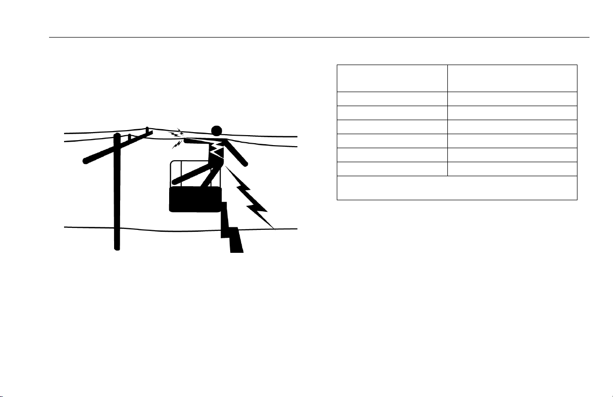
Electrocution Hazards
• This machine is not insulated and does not provide protection from contact or proximity to electrical current.
• Maintain distance from electrical lines, apparatus, or any
energized (exposed or insulated) parts according to the
Minimum Approach Distance (MAD) as shown in Table 1-
1.
• Allow for machine movement and electrical line swaying.
Table 1-1. Minimum Approach Distances (M.A.D.)
Voltage Range
(Phase to Phase)
0 to 50 KV 10 (3)
Over 50KV to 200 KV 15 (5)
Over 200 KV to 350 KV 20 (6)
Over 350 KV to 500 KV 25 (8)
Over 500 KV to 750 KV 35 (11)
Over 750 KV to 1000 KV 45 (14)
NOTE: This requirement shall apply except where employer,
local or governmental regulations are more stringent.
• Maintain a clearance of at least 10 ft. (3m) between any
part of the machine and its occupants, their tools, and
their equipment from any electrical line or apparatus carrying up to 50,000 volts. One foot additional clearance is
required for every additional 30,000 volts or less.
• The minimum approach distance may be reduced if insulating barriers are installed to prevent contact, and the
barriers are rated for the voltage of the line being guarded.
These barriers shall not be part of (or attached to) the
machine. The minimum approach distance shall be
reduced to a distance within the designed working dimensions of the insulating barrier. This determination shall be
MINIMUM APPROACH DISTANCE
in Feet (Meters)
3121153 – JLG Lift – 1-5
Page 16
SECTION 1 - SAFETY PRECAUTIONS
DANGER
made by a qualified person in accordance with the
employer, local, or governmental requirements for work
practices near energized equipment
DO NOT MANEUVER MACHINE OR PERSONNEL INSIDE PROHIBITED
ZONE (MAD). ASSUME ALL ELECTRICAL PARTS AND WIRING ARE
ENERGIZED UNLESS KNOWN OTHERWISE.
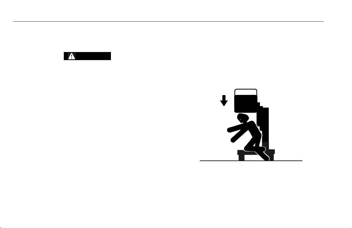
Crushing And Collision Hazards
• Personal protection equipment must be worn by all operating and ground personnel.
• Check work area clearances above, on sides, and bottom
while lifting or lowering the platform.
• During platform operation, keep all body parts inside platform railing.
• Keep non-operating personnel at least 6 ft. (1.8m) away
while operating machine.
1-6 – JLG Lift – 3121153
Page 17

SECTION 1 - SAFETY PRECAUTIONS
• Exercise extreme caution at all times to prevent obstacles
from striking or interfering with operating controls and person in the platform.
• Ensure that operators of other overhead and floor level
machines are aware of the aerial work platform’s presence. Disconnect power to overhead cranes.
• Warn personnel not to work, stand, or walk under a raised
platform. Position barricades on floor as necessary.
1.4 LIFTING MACHINE
• When lifting machine with a forklift, position forks only at
designated areas of the machine. Lift with a forklift of adequate capacity.
• Ensure machine is secure on the forks before transporting. Keep machine as low to the ground as possible.
• Refer to the Machine Operation section of this manual for
lifting information.
3121153 – JLG Lift – 1-7
Page 18

SECTION 1 - SAFETY PRECAUTIONS
NOTES:
1-8 – JLG Lift – 3121153
Page 19

SECTION 2 - USER RESPONSIBILITIES, MACHINE PREPARATION, AND INSPECTION
SECTION 2. USER RESPONSIBILITIES, MACHINE PREPARATION, AND INSPECTION
2.1 Personnel Training
The aerial platform is a personnel handling device; so it is necessary that it be operated and maintained only by trained personnel.
Persons under the influence of drugs or alcohol or who are subject
to seizures, dizziness or loss of physical control must not operate
this machine.
Operator Training
Operator training must cover:
1. Use and limitations of the controls in the platform and at
the ground, emergency controls and safety systems.
2. Control labels, instructions, and warnings on the
machine.
3. Rules of the employer and government regulations.
4. Use of approved fall protection device.
5. Enough knowledge of the mechanical operation of the
machine to recognize a malfunction or potential malfunction.
6. The safest means to operate the machine around overhead obstructions and other moving equipment.
7. Means to avoid the hazards of unprotected electrical
conductors.
8. Specific job requirements or machine application.
Training Supervision
Training must be done under the supervision of a qualified person
in an open area free of obstructions until the trainee has developed the ability to safely control and operate the machine.
Operator Responsibility
The operator must be instructed that he/she has the responsibility
and authority to shut down the machine in case of a malfunction or
other unsafe condition of either the machine or the job site.
3121153 – JLG Lift – 2-1
Page 20

SECTION 2 - USER RESPONSIBILITIES, MACHINE PREPARATION, AND INSPECTION
NOTICE
2.2 Preparation, Inspection, and Maintenance
The following table covers the periodic machine inspections and
maintenance recommended by JLG Industries, Inc. Consult local
regulations for further requirements for aerial work platforms. The
frequency of inspections and maintenance must be increased as
necessary when the machine is used in a harsh or hostile environment; if the machine is used with increased frequency; or if the
machine is used in a severe manner.
JLG INDUSTRIES, INC. RECOGNIZES A FACTORY TRAINED SERVICE
TECHNICIAN AS A PERSON WHO HAS SUCCESSFULLY COMPLETED
THE JLG SERVICE TRAINING SCHOOL FOR THE SPECIFIC JLG PRODUCT MODEL.
2-2 – JLG Lift – 3121153
Page 21

SECTION 2 - USER RESPONSIBILITIES, MACHINE PREPARATION, AND INSPECTION
Table 2-1. Inspection and Maintenance Table
TYPE FREQUENCY
Pre-Start Inspection Before using each day; or
whenever there’s an Operator change.
Pre-Delivery Inspection
(See Note)
Frequent Inspection In service for 3 months, whichever comes first;
Annual Machine Inspection Annually, no later than 13 months from the date of
Preventative Maintenance At intervals as specified in the Service and Main-
NOTE: Inspection forms are available from JLG. Use the Service and Maintenance Manual to perform inspections.
Before each sale, lease, or rental delivery. Owner, Dealer, or User Qualified JLG
or;
Out of service for a period of more than 3 months;
or
Purchased used.
prior inspection.
tenance Manual.
PRIMARY
RESPONSIBILITY
User or Operator User or Operator Operator and Safety Manual
Owner, Dealer, or User Qualified JLG
Owner, Dealer, or User Factor y Trained
Owner, Dealer, or User Qualified JLG
SERVICE
QUALIFICATION
Mechanic
Mechanic
Service Technician
(Recommended)
Mechanic
Service and Maintenance
Manual and applicable JLG
inspection form
Service and Maintenance
Manual and applicable JLG
inspection form
Service and Maintenance
Manual and applicable JLG
inspection form
Service and Maintenance
Manual
REFERENCE
3121153 – JLG Lift – 2-3
Page 22

SECTION 2 - USER RESPONSIBILITIES, MACHINE PREPARATION, AND INSPECTION
Pre-Start Inspection
The Pre-Start Inspection should include each of the following:
1. Cleanliness – Check all surfaces for oil leakage or foreign objects. Report any leakage to the proper maintenance personnel.
2. Decals and Placards – Check all for cleanliness and
legibility. Make sure none of the decals and placards are
missing. Make sure all illegible decals and placards are
cleaned or replaced.
3. Operators and Safety Manuals – Make sure a copy of
the Operator and Safety Manual, EMI Safety Manual
(Domestic only), and ANSI Manual of Responsibilities
(Domestic only) is enclosed in the weather resistant
storage container.
4. “Walk-Around” Inspection – Refer to Figure 2-1. and
Section 2.3.
5. Hydraulic Oil – Check the hydraulic oil level. Ensure
hydraulic oil is added as required.
6. Function Check – Once the “Walk-Around” Inspection
is complete, perform a function check of all systems in
an area free of overhead and ground level obstructions.
Refer to Machine Operation section for more specific
instructions on the operation of each function.
IF THE MACHINE DOES NOT OPERATE PROPERLY, TURN OFF THE
MACHINE IMMEDIATELY! REPORT THE PROBLEM TO THE PROPER MAINTENANCE PERSONNEL. DO NOT OPERATE THE MACHINE UNTIL IT IS
DECLARED SAFE FOR OPERATION.
2-4 – JLG Lift – 3121153
Page 23

SECTION 2 - USER RESPONSIBILITIES, MACHINE PREPARATION, AND INSPECTION
CAUTION
2.3 WALK-AROUND INSPECTION
(See Figure 2-1.)
General
Begin the Walk-Around Inspection at item 1 below. Continue
around machine checking each item in this check list.
TO AVOID POSSIBLE INJURY, BE SURE MACHINE POWER IS OFF DURING WALK-AROUND INSPECTION.
INSPECTION NOTE: On each item, make sure there are no loose
or missing parts, that they are securely fastened and that
no visible damage exists in addition to any other criteria
mentioned.
1. Base Frame - Properly secured to work surface. See
Inspection Note.
2. Manual Descent Control Valve - No evidence of
hydraulic leaks.
3. Motor/Pump/Reservoir Power Unit - No evidence of
hydraulic leaks. Check that hydraulic reservoir fluid level
is filled to the "Fill to Line" mark on the side of the reservoir.
4. Ground Controls - Key switch operable; emergency
stop switch properly set for operation.
5. Mast Assembly - Inspect mast chains and sequence
cables as per inspection note. Control and power cables
properly tensioned and seated in control cable sheaves;
control cable sheaves rotate freely.
6. AC Voltage Junction Box - Secure to support, access
door secure and closed.
7. Platform Controls - Inspect UP/DOWN and Function
Enable buttons as per inspection note. Emergency Stop
switch functions properly. Operation & Safety Manual in
manual storage box.
8. Platform Control Foot Switches (optional) - Inspect
UP and DOWN foot pedals. Ensure foot switch enclosure is properly secured to the platform floor.
9. Platform Assembly - Secure to mast; Properly secured
to mounting brackets; entry gate(s) closing properly.
10. Hourmeter - Hourmeter secure and legible.
3121153 – JLG Lift – 2-5
Page 24

SECTION 2 - USER RESPONSIBILITIES, MACHINE PREPARATION, AND INSPECTION
1
2
3
4
5
6
7
8
9
10
8
1. Base Frame
2. Manual Descent Control Valve
3. Motor/Pump/Reservoir Power Unit
4. Ground Controls
5. Mast Assembly
6. AC Junction Box Assembly
7. Platform Controls
8. Platform Control Foot Switches (option)
9. Platform Assembly
10. Hourmeter
Figure 2-1. Daily Walk-Around inspection.
(Shown with Standard Platform)
2-6 – JLG Lift – 3121153
Page 25

SECTION 2 - USER RESPONSIBILITIES, MACHINE PREPARATION, AND INSPECTION
2.4 FUNCTION CHECK
The function check of all systems should be performed in an area
free of overhead and ground level obstructions. Perform a function
check as follows:
1. Set-up machine for operation, according to operating
instructions in Section 4.
2. Enter platform, raise and lower platform 2 ft. to 3 ft.
(.61m to .92 m) several times. Check for smooth elevation and lowering of platform.
3. With the aid of an assistant in the platform, test the manual decent valve. Elevate the platform approximately 12
inches, then activate the manual decent function, pull
and hold the red knob until the platform is completely
lowered.
4. Ensure that all machine functions are disabled when the
Emergency Stop Switch is pressed.
5. With platform completely lowered, check hydraulic oil
level in reservoir at ground control station. Maintain an
oil level to the "Fill to Line" indicator on the side of the
reservoir. NEVER USE HYDRAULIC BRAKE FLUID.
6. If equipped with the optional platform gate interlocks,
verify the lift function does not operate with either gate
open.
NOTE: To verify if the machine is equipped with the optional gate
interlocks, look for a wire harness to exit the platform midrail through a small hole in the midrail near the mast
header.
7. Machines equipped with the optional platform foot
switch controls, check proper operation for elevating
and lowering of the platform.
3121153 – JLG Lift – 2-7
Page 26

SECTION 2 - USER RESPONSIBILITIES, MACHINE PREPARATION, AND INSPECTION
NOTES:
2-8 – JLG Lift – 3121153
Page 27

SECTION 3 - MACHINE CONTROLS AND INDICATORS
NOTICE
SECTION 3. MACHINE CONTROLS AND INDICATORS
3.1 GENERAL
THE MANUFACTURER HAS NO DIRECT CONTROL OVER MACHINE
APPLICATION AND OPERATION. THE USER AND OPERATOR ARE
RESPONSIBLE FOR CONFORMING WITH GOOD SAFETY PRACTICES.
This section provides the necessary information needed to understand control functions.
3.2 CONTROLS AND INDICATORS
Ground Control Station (See Figure 3-1.)
1. POWER ON/OFF Key Switch
A key switch located on the ground control station controls power to all functions on the machine. The machine
will not operate without the key inserted and turned to the
ON position. When left unattended, removing the key will
prevent unauthorized operaton.
2. EMERGENCY STOP SWITCH
A two position mushroom shaped switch furnishes power
to the platform and ground controls when RESET (ON).
When pushed in (OFF), power is shut off to the platform
and ground controls.
3. HYDRAULIC RESERVOIR/CIRCUIT BREAKER/FUSE
(located inside the ground control station housing)
The hydraulic oil level can be checked through an access
hole in the side of the cover.
NOTE: Check hydraulic oil only when platform is completely low-
ered and after cycling platform up/down a few times.
NOTE: A replaceable 5 Amp fuse for the DC Voltage circuit and a
reset type circuit breaker for the AC Voltage circuit is
located in the AC Junction Box on BD Models.
4. HOURMETER
The machine hourmeter registers pump operation time
during the platform LIFT UP cycle only. The hourmeter is
located on the back of the Ground Control Station on the
pump mounting bracket.
3121153 – JLG Lift – 3-1
Page 28

SECTION 3 - MACHINE CONTROLS AND INDICATORS
2
3
1
4
2
1
Manual Descent Valve Location
(See Figure 3-2.)
Located at the rear and bottom of the base frame. This
PULL TO RELEASE - spring loaded return valve (RED
Knob), allows for lowering of the platform in an emergency
or power failure.
Figure 3-1. Ground Control Station.
1. Power ON/OFF Key Switch
2. Emergency Stop Switch
3. Hydraulic Reservoir/Circuit
Breaker/Fuse
4. Hourmeter
Figure 3-2. Manual Descent Valve Location.
1. Manual Descent Valve 2. Rear of Base Frame Assembly
3-2 – JLG Lift – 3121153
Page 29

SECTION 3 - MACHINE CONTROLS AND INDICATORS
Platform Control Station
(See Figure 3-3.)
1. EMERGENCY STOP SWITCH
A two position mushroom shaped switch furnishes power
to the platform controls when pulled out (ON). When
pushed in (OFF), power is shut off to the platform.
2. PLATFORM UP Button (WHITE)
When depressed simultaneously with ENABLE (GREEN)
button raises the platform.
3. FUNCTION ENABLE Button.
This (GREEN) button must be depressed simultaneously
with either the UP or DOWN platform function buttons in
order to raise or lower the platform.
4. PLATFORM DOWN Button (WHITE).
When depressed simultaneously with ENABLE (GREEN)
button lowers the platform.
Figure 3-3. Platform Control Station.
1. Emergency Stop Switch (RED)
2. Platform UP - (WHITE)
3. Function Enable - (GREEN)
4. Platform DOWN - (WHITE)
3121153 – JLG Lift – 3-3
Page 30

SECTION 3 - MACHINE CONTROLS AND INDICATORS
18 Ft. Height Limiter - (19BD ONLY - OPTION)
19BD machines may be equipped with an 18 ft. height limiter option. This option prevents the platform from elevating beyond a height of 18 ft. Otherwise the platform will
operate normally.
Platform Gate Interlock - (OPTION)
If equipped, the optional platform gate interlock will prevent the platform lift function from operating when either
gate is open.
NOTE: To verify if the machine is equipped with the optional gate
interlocks, look for a wire harness to exit the platform midrail through a small hole in the midrail near the mast
header.
Platform Gate Lock - (OPTION) - S/N-0130016195 to Present
If equipped, the optional platform gate lock will prevent the
platform lift function from operating if the platform gates
are not closed and the lock slide bar is not engaged.
Once the slide bar is engaged and gates locked, the slide
bar will only disengage when the platform is fully lowered.
3-4 – JLG Lift – 3121153
Page 31

SECTION 3 - MACHINE CONTROLS AND INDICATORS
2
1
3
(See Figure 3-4.)
Platform Foot Control Switches - (OPTION)
1. FOOTSWITCH Operation Decal.
Shows which pedal controls platform lift up and lift down.
2. PLATFORM DOWN Pedal.
When depressed simultaneously with FUNCTION
ENABLE button located on the platform control station,
LOWERS the platform.
3. PLATFORM UP Pedal.
When depressed simultaneously with FUNCTION
ENABLE button located on the platform control station,
RAISES the platform.
Figure 3-4. Platform Control Footswitch
1. Footswitch Operation Decal 2. Platform DOWN Pedal
3. Platform UP Pedal
3121153 – JLG Lift – 3-5
Page 32

SECTION 3 - MACHINE CONTROLS AND INDICATORS
1
3
3
3
3
2
4
5
6
15
7
7
8
9
10
10
11
12
13
14
3-6 – JLG Lift – 3121153
Figure 3-5. 15BD/19BD - Decal Installation
Page 33

SECTION 3 - MACHINE CONTROLS AND INDICATORS
Table 3-1. 15BD/19BD - Decal Installation
ITEM # PART NUMBER DESCRIPTION
0272159 DECAL INSTALLATION
1 1700584 Decal - Patent
2 1702631 Decal - Bar Code
3 1703073 Decal - Fork Pockets
4 1705633 Decal - Function Controls
5 1703781 Decal - Electrical Hazard
6 1705635 Decal - Maximum Capacity
7 1705634 Decal - Crushing Hazard
8 1703788 Decal - Manual
9 1705220 Decal - Warning
10 1703072 Decal - No Fork-Lifting Here
11 1705636 Decal - Manual Descent
12 1001111596 Nameplate - Serial Number
13 1702120 Decal - Extension Cord Wire Size
14 1702569 Decal - Electrical Voltage
15 1703166 Decal - Footswitch Operation (optional)
3121153 – JLG Lift – 3-7
Page 34

SECTION 3 - MACHINE CONTROLS AND INDICATORS
NOTES:
3-8 – JLG Lift – 3121153
Page 35

SECTION 4 - MACHINE OPERATION
SECTION 4. MACHINE OPERATION
4.1 DESCRIPTION
This machine is a stationary base frame - bolt down version of
JLG’s manually propelled AM-AC model vertical lift. It features a
work platform mounted to an elevating aluminum mast mechanism. The personnel lift’s intended purpose is to provide personnel (with their tools and supplies) access to areas above ground
level.
The main power is turned on/off at the ground control station, an
emergency stop switch is located directly next to the main power
key switch.
The primary operator control station is located in the platform.
From this control station, the operator can raise and lower the platform. An emergency stop switch is located here also.
A platform manual descent valve is located inside the base frame
at the rear of the machine. This valve will lower the platform to the
ground in an emergency or if a power failure should occur and the
operator in the platform is unable to do so.
4.2 OPERATING CHARACTERISTICS AND LIMITATIONS
Capacities
MACHINE BASE FRAME MUST BE PROPERLY SECURED TO IT’S WORK
AREA MOUNTING SURFACE USING A MINIMUM OF 1/2" (19MM) DIAMETER GRADE 5 FASTENERS (OR EQUIVALENT) AND WIDE FLATWASHERS
BEFORE ATTEMPTING TO OPERATE LIFT.
NOTE: Refer to Service and Maintenance Manual for bolt down
specifications.
The platform can be raised above the stowed position if:
• The machine is properly and securely mounted to a firm
and level surface.
• Load is within manufacturer’s maximum rated capacity.
• All machine functions are operating properly.
3121153 – JLG Lift – 4-1
Page 36

SECTION 4 - MACHINE OPERATION
4.3 SET-UP AND OPERATION
DO NOT ATTEMPT TO RAISE THE PLATFORM UNTIL THE MACHINE IS
PROPERLY SECURED TO THE WORK AREA MOUNTING SURFACE.
To set-up the machine for operation the operator must:
1. Turn key switch to the ON position at the ground control
station.
2. Ensure both emergency stop switches, (one at platform
controls and one at ground controls), are in the RESET
(pulled out) position for operation.
3. Ensure manual decent control valve (red knob) located
on the rear base frame is closed (spring loaded - default
position).
Platform Loading
JLG INDUSTRIES, INC. RECOMMENDS THE OPERATOR IN THE PLATFORM
USE AN APPROVED FALL RESTRAINT DEVICE WITH A LANYARD
ATTACHED TO AN AUTHORIZED LANYARD ANCHORAGE POINT.
The platform maximum rated load capacity is shown on a placard
located on the platform control panel.
Platform Operation
1. Enter platform and close the entry gate(s).
NOTE: Machines equipped with optional entry gate interlocks,
the platform controls will not lift or lower without both
gates completely closed. To verify if the machine is
equipped with the optional gate interlocks, look for a wire
harness to exit the platform midrail through a small hole in
the midrail near the mast header.
2. To raise the platform, depress the FUNCTION ENABLE
button and platform UP button simultaneously. Upon
reaching desired elevation level, release the UP and
FUNCTION ENABLE buttons.
NOTE: Machines equipped with the optional platform foot control
switches, the footswitch is equipped with two pedals, one
labeled UP and one labeled DOWN. These pedals work
the same as the UP/DOWN buttons on the platform control station. The FUNCTION ENABLE button must be
depressed before either foot pedal will raise or lower the
platform.
4-2 – JLG Lift – 3121153
Page 37

ENSURE AREA BENEATH PLATFORM IS FREE OF PERSONNEL AND
1
2
3
OBSTRUCTIONS PRIOR TO LOWERING PLATFORM.
3. To lower platform, depress FUNCTION ENABLE button
and platform DOWN button on control panel simultaneously.
SECTION 4 - MACHINE OPERATION
4.4 Platform Configurations
STANDARD PLATFORM
Model Max. Capacity
15BD and 19BD 350 lb. (160kg)
1. Side Swinging Entry Gate 3. Lanyard Attach Point -
2. Platform Control Station (round bar in corner of mid rail)
3121153 – JLG Lift – 4-3
Page 38

SECTION 4 - MACHINE OPERATION
1
3
2
GULL-WING - FRONT ENTRY PLATFORM - OPTION
Model Max. Capacity
15BD and 19BD 350 lb. (160kg)
1. Front Gull-Wing Entry Gate 3. Lanyard Attach Point - (mounted
2. Entry Gate Latch on side of mast assembly)
4.5 Machine Shut down
1. Ensure that platform is fully lowered, push in the emergency stop at the platform controls. Exit the platform
and push in the emergency stop at the ground control
station. Turn the key switch to the OFF position.
2. If necessary, remove the key from the key switch at the
ground control station to disable the machine from
unauthorized use.
4-4 – JLG Lift – 3121153
Page 39

SECTION 5 - OPTIONAL EQUIPMENT
SECTION 5. OPTIONAL EQUIPMENT
5.1 OPTIONAL EQUIPMENT
The following optional equipment is available for 15BD model
machines:
28" x 26" Front Entry Gullwing Platform
The 28" (71cm) long by 26" (66cm) wide platform features a gull
wing gate opening.
Tool/Bottle Tray
Platform attachment to hold hand tools or other small items
placed in the tray.
Platform Foot Control Switch
This is a dual footswitch operated control that is mounted on the
floor of the platform. These switches in conjunction with the
function enable switch (GREEN) on the platform control panel,
allows control of the UP (raising) and Down (lowering) of the
platform.
Tube Carrier (PVC)
These carriers are mounted to the right side of the mast assembly, just behind the platform rail. They are approximately 3.5 in
in diameter and are approx. 45 inches in length and allow for
storage of materials that may be required while working in the
platform.
18 Ft. Height Limiter - (19BD ONLY - OPTION)
The platform limiter switch when installed on the 19BD model
lift, limits the platform to a maximum height of 18 ft. This can be
useful when platform height must be limited due to ceiling
height, or a specific work height is required.
Platform Gate Interlock - (OPTION)
If equipped, the optional platform gate interlock will prevent the platform lift function from operating with either
gate open.
NOTE: To verify if the machine is equipped with the optional gate
interlocks, look for a wire harness to exit the platform midrail through a small hole in the midrail near the mast
header.
3121153 – JLG Lift – 5-1
Page 40

SECTION 5 - OPTIONAL EQUIPMENT
Platform Gate Lock - (OPTION) - S/N-0130016195 to Present
If equipped, the optional platform gate lock will prevent the
platform lift function from operating if the platform gates
are not closed and the lock slide bar is not engaged.
Once the slide bar is engaged and gates locked, the slide
bar will only disengage when the platform is fully lowered.
5-2 – JLG Lift – 3121153
Page 41

SECTION 6 - EMERGENCY PROCEDURES
NOTICE
SECTION 6. EMERGENCY PROCEDURES
6.1 GENERAL INFORMATION
This section explains the steps to be taken in case of an emergency situation while operating the machine.
6.2 EMERGENCY OPERATION
Operator Unable to Control Machine
IF THE PLATFORM OPERATOR IS PINNED, TRAPPED OR
UNABLE TO OPERATE OR CONTROL THE MACHINE, USE THE
FOLLOWING INSTRUCTIONS AS A GUIDELINE. DO NOT CONTINUE OPERATION IF CONTROLS DO NOT FUNCTION PROPERLY
1. If the operator is unable to lower the platform from the
platform controls, other personnel should operate the
emergency descent control valve located at the rear of
the machines base frame, “Manual Descent Valve Location” on page 3-2, to lower the platform.
2. If necessary, rescue equipment can be used to remove
the platform occupant and stabilize motion of the
machine.
Platform Caught Overhead
If the platform becomes jammed or snagged in overhead structures or equipment, rescue the platform occupant prior to freeing
the machine.
6.3 INCIDENT NOTIFICATION
JLG Industries, Inc. must be notified immediately of any incident
involving a JLG product. Even if no injury or property damage is
evident, the factory should be contacted by telephone and provided with all necessary details.
JLG Phone: USA: 877-JLG-SAFE (554-7233)
(8am till 4:45pm EST)
Email (USA): productsafety@jlg.com
Failure to notify the Manufacturer of an incident involving a JLG
Industries product within 48 hours of such an occurrence may
void any warranty consideration on that particular machine.
FOLLOWING ANY INCIDENT, THOROUGHLY INSPECT THE MACHINE
AND TEST ALL FUNCTIONS. DO NOT ELEVATE PLATFORM UNTIL YOU
ARE SURE THAT ALL DAMAGE HAS BEEN REPAIRED, IF REQUIRED,
AND THAT ALL CONTROLS ARE OPERATING CORRECTLY.
3121153 – JLG Lift – 6-1
Page 42

SECTION 6 - EMERGENCY PROCEDURES
NOTES:
6-2 – JLG Lift – 3121153
Page 43

SECTION 7 - GENERAL SPECIFICATIONS AND OPERATOR MAINTENANCE
SECTION 7. GENERAL SPECIFICATIONS AND OPERATOR MAINTENANCE
7.1 Introduction
This section of the manual provides additional necessary information to the operator for proper operation and maintenance of this
machine.
The maintenance portion of this section is intended as information
to assist the machine operator to perform daily maintenance tasks
only, and does not replace the more thorough Preventive Maintenance and Inspection Schedule included in the Service and Maintenance Manual.
Other Publications Available Specific to this Machine:
Service and Maintenance Manual
ANSI. . . .. . . . . . . .. . . . . .. . . . . .. . . . . .. . . . . 3121154
Illustrated Parts Manual
ANSI. . . .. . . . . . . .. . . . . .. . . . . .. . . . . .. . . . . 3121155
3121153 – JLG Lift – 7-1
Page 44

SECTION 7 - GENERAL SPECIFICATIONS AND OPERATOR MAINTENANCE
7.2 General Specifications
Machine Specifications
SPECIFICATION
Maximum Occupants: (Persons) 1
Maximum Work Load
(Platform Capacity):
Machine Stowed Height: 77.22 in. (1.96 m) 77.81 in. (1.97 m)
Machine Stowed Width: 29.75 in. (75.5 cm)
Maximum Vertical Platform Height
(Ground to Platform Floor - Platform
Fully Extended):
Maximum Step-in Platform Height
(Ground to Platform Floor - Platform
Fully Lowered):
Working Height: 21 ft. (6.4 m) 24.75 ft. (7.54 m)
Standard Platform Size: 27 in. x 23 in.
Platform Speed (seconds) Lift Up: 20 22
( w/ m a x . r a t ed l o a d) L i f t D o w n: 32 - 40 18 - 25
Machine Weight (Platform Empty ): 725 lb. (329 kg) 830 lb. (376 kg)
15BD 19BD
350 lb. (160 kg)
15.25 ft. (4.65 m) 18.75 ft. (5.72 m)
12.75 in. ( cm) 13.37 in. ( cm)
(68.5 cm x 58.5 cm)
SPECIFICATION
System Voltage: 12V DC/120 Volts-60Hz AC
Machine Base Mounting Footprint: 18 in. x 33 in.
15BD 19BD
(45.72 cm x 83.82 cm)
0.75 Dia. Holes
20 in. x 24 in.
(50.8 cm x 60.96 cm)
0.75 Dia. Holes
Serial Number Locations
For machine identification, a serial number plate is affixed to the
machine. The plate is located on the back of the mast, just above
the mast support bracket.
7-2 – JLG Lift – 3121153
Page 45

7.3 Operator Maintenance
Lubrication
Hydraulic Oil (HO)
SECTION 7 - GENERAL SPECIFICATIONS AND OPERATOR MAINTENANCE
Table 7-1. - Lubrication Specifications
HYDRAULIC SYSTEM OPERATING
TEMPERATURE RANGE
+0° F to +180° F (-18° C to -83° C) 10W
+0° F to +210° F (-18° C to +99° C) 10W-20, 10W-30
+50° F to +210° F (+10° C to +99° C) 20W-20
Hydraulic oils must have anti-wear qualities at least to API Service
Classification GL-3, and sufficient chemical stability for mobile
hydraulic system service. JLG Industries, recommends Mobilfluid
424 hydraulic oil, which has an SAE viscosity of 10W-30 and a viscosity index of 152.
For cold weather applications, i.e. when temperatures remain consistently below +20°F (–7°C) JLG recommends using Mobil DTE
13 hydraulic oil.
Aside from JLG recommendations, it is not advisable to mix oils of
different brands or types, as they may not contain the same
required additives or be of comparable viscosities. If use of
hydraulic oil other than Mobilfluid 424 is desired, contact JLG
Industries for proper recommendations.
SAE VISCOSITYGRADE
KEY SPECIFICATIONS
MPG - Multipurpose Grease having a minimum dripping point of 350° F.
Excellent water resistance and adhesive qualities, and being of
extreme pressure type. (Timken OK 40 pounds minimum.)
EPGL - Extreme Pressure Gear Lube (oil) meeting API service classification
G L-5 or MI L-S pe c M IL- L-21 05.
HO - Hydraulic Oil. ISO-Vg grade 32, 46.
CL - Chain Lube. Use a good quality chain lubricant
NOTE: Refer to Lubrication Chart, Table 7-2. for specific lubrica-
tion locations on machine.
3121153 – JLG Lift – 7-3
Page 46

SECTION 7 - GENERAL SPECIFICATIONS AND OPERATOR MAINTENANCE
1
2
Table 1-1. 15BD Lubrication Points (See Table 7-2. on page 7-5)
7-4 – JLG Lift – 3121153
Page 47

SECTION 7 - GENERAL SPECIFICATIONS AND OPERATOR MAINTENANCE
Table 7-2. Lubrication Intervals for Various Components
ITEM COMPONENT
Hydraulic Oil Fill To Line
1
NO/TYPE
LUBE POINTS
(a)
LUBE/METHOD
HO- Check Hyd.
on Reservoir
5 Qt. (4.3 L)
Reservoir
Mast Chains 2 - Per Section Chain Lube - Br ush or
2
HO-Change
H y d. O il
Spray
Oil Level
3
MONTHS
or
5 Hm.Hrs.
INTERVAL HOURS
6
MONTHS
or
10 Hm.Hrs.
1
YEAR
or
20 Hm.Hrs.
(b)
2
YEARS
or
40 Hm.Hrs.
Check hydraulic oil level
(c)
daily.
Change oil after every 40
Hourmeter Hrs. of operation.
Key to Lubricants: MPG - Multipurpose Grease
(See Table 7-1) HO - Hydraulic Oil
Notes: a. Be certain to lubricate like items on each side of the machine.
b. Recommended lubricating intervals are calculated on hourmeter hours (Hm.Hrs.= pump run cycle - lift up - only).
Recommended lubricating intervals are based on normal use. If machine is subjected to severe operating conditions, such as a high
number of cycles, location, corrosive/dirty environment, etc., user must adjust lubricating requirements accordingly.
c. Prior to checking hydraulic oil level, operate machine through one complete cycle of lift function (full up and down). Ensure platform is
fully lowered, failure to do so will result in incorrect oil level reading on the hydraulic reser voir.
COMMENTS
3121153 – JLG Lift – 7-5
Page 48

SECTION 7 - GENERAL SPECIFICATIONS AND OPERATOR MAINTENANCE
NOTES:
7-6 – JLG Lift – 3121153
Page 49

SECTION 8 - INSPECTION AND REPAIR LOG
SECTION 8. INSPECTION AND REPAIR LOG
Table 8-1. Inspection and Repair Log
Date Comments
Machine Serial Number: _________________________
3121153 – JLG Lift – 8-1
Page 50

SECTION 8 - INSPECTION AND REPAIR LOG
Table 8-1. Inspection and Repair Log
Date Comments
Machine Serial Number: _________________________
8-2 – JLG Lift – 3121153
Page 51

TRANSFER OF OWNERSHIP
To Product Owner:
If you now own but ARE NOT the original purchaser of the product covered by this
manual, we would like to know who you are. For the purpose of receiving safety-related
bulletins, it is very important to keep JLG Industries, Inc. updated with the current
ownership of all JLG products. JLG maintains owner information for each JLG product
and uses this information in cases where owner notification is necessary.
Please use this form to provide JLG with updated information with regard to the
current ownership of JLG products. Please return completed form to the JLG Product
Safety & Reliability Department via facsimile or mail to address as specified below.
Thank You,
Product Safety & Reliability Department
JLG Industries, Inc.
13224 Fountainhead Plaza
Hagerstown, MD 21742
USA
Telephone: +1-717-485-6591
Fax: +1-301-745-3713
NOTE: Leased or rented units should not be included on this form.
Mfg. Model: _____________
__________________________________________________
Serial Number: ____________________________________________________________
Previous Owner: ___________________________________________________________
Address: _________________________________________________________________
_________________________________________________________________________
Country: _________________________ Telephone: (_______
) ____________________
Date of Transfer: _________________________________
Current Owner: ____________________________________________________________
Address: _______________
__________________________________________________
_________________________________________________________________________
Country: _________________________ Telephone: (_______
) ____________________
Who in your organization should we notify?
Name: ___________________________________________________________________
Title:____________________________________________________________________
An Oshkosh Corporation Company
Page 52

Page 53

Page 54

JLG Industries, Inc.
31
21153
1 JLG Drive
McConnellsburg PA. 17233-9533
USA
(717) 485-5161
(717) 485-6417
JLG Worldwide Locations
JLG Industries (Australia)
P.O. Box 5119
11 Bolwarra Road
Port Macquarie
N.S.W. 2444
Australia
+61 2 65 811111
+61 2 65 810122
JLG Deutschland GmbH
Max-Planck-Str. 21
D - 27721 Ritterhude - Ihlpohl
Germany
+49 (0)421 69 350 20
+49 (0)421 69 350 45
JLG Polska
UI. Krolewska
00-060 Warsawa
Poland
+48 (0)914 320 245
+48 (0)914 358 200
JLG Latino Americana Ltda.
Rua Eng. Carlos Stevenson,
80-Suite 71
13092-310 Campinas-SP
Brazil
+55 19 3295 0407
+55 19 3295 1025
JLG Equipment Services Ltd.
Rm 1107 Landmark North
39 Lung Sum Avenue
Sheung Shui N. T.
Hong Kong
(852) 2639 5783
(852) 2639 5797
Plataformas Elevadoras
JLG Iberica, S.L.
Trapadella, 2
P.I. Castellbisbal Sur
08755 Castellbisbal, Barcelona
Spain
+34 93 772 4700
+34 93 771 1762
JLG Industries (UK) Ltd
Bentley House
Bentley Avenue
Middleton
Greater Manchester
M24 2GP - England
+44 (0)161 654 1000
+44 (0)161 654 1001
JLG Industries (Italia) s.r.l.
Via Po. 22
20010 Pregnana Milanese - MI
Italy
+39 029 359 5210
+39 029 359 5845
JLG Sverige AB
Enkopingsvagen 150
Box 704
SE - 176 27 Jarfalla
Sweden
+46 (0)850 659 500
+46 (0)850 659 534
JLG France SAS
Z.I. de Baulieu
47400 Fauillet
France
+33 (0)5 53 88 31 70
+33 (0)5 53 88 31 79
Oshkosh - JLG Singapore T. E. P. Ltd.
29 Tuas Ave 4
Jurong Industrial Estate
639379
Singapore
+65-6591-9030
+65-6591-9031
www.jlg.com
 Loading...