


UV8020
Installation and Operation Manual
CONTENTS
Thank you for choosing a Phase Linear product. We hope you will find the instructions in this owner’s manual clear and easy to follow. If you take a few minutes to look through it, you’ll
learn how to use all the features of your new Phase Linear UV8020 Mobile Multimedia |
|
Receiver for maximum enjoyment. |
|
Preparation............................................................................................................................ |
1 |
Installation ............................................................................................................................. |
2 |
Controls and Indicators ......................................................................................................... |
5 |
Remote Control ..................................................................................................................... |
6 |
Using the TFT Monitor .......................................................................................................... |
8 |
Operating Instructions ........................................................................................................... |
9 |
DVD Setup Menu ................................................................................................................ |
11 |
Tuner Operation .................................................................................................................. |
12 |
DVD/VCD Video Operation ................................................................................................. |
13 |
DVD/CD Audio Operation ................................................................................................... |
16 |
MP3/WMA Operation .......................................................................................................... |
18 |
Troubleshooting .................................................................................................................. |
21 |
Specifications ...................................................................................................................... |
23 |
i
ii

UV8020
PREPARATION
Congratulations on your purchase of the Phase Linear UV8020 Mobile Multimedia Receiver.
It’s a good idea to read all of the instructions before beginning the installation. We recommend having your Phase Linear UV8020 installed by a reputable installation shop.
Features
DVD
•Aspect Ratio - Full and Normal
•Fast Forward/Backward - 2X, 4X, 8X and 20X
•Play, Pause, Stop, Next Chapter and Previous Chapter
CD / MP3 / WMA
•ID3 Tag Compatible
•Directory Search (MP3 / WMA Only)
•Direct Track Access via Remote Control
•Burn up to 1500 MP3 and WMA Files onto a DVD+R / RW
•Random, Repeat and Intro
•Play, Pause, Stop, Next Track and Previous Track
AM-FM
•30 Station Presets (18 FM / 12 AM)
•Auto Stereo / Mono
•Auto Store / Preview Scan
Auxiliary Input
•Front Auxiliary Input (audio and video)
•2.5mm to 3.5mm A/V Cable Included
•2.5mm to RCA A/V Cable Included
Chassis
•2.0 DIN (Import / ISO-DIN Mountable)
•Motorized Slide Down LCD Screen
•7" TFT Active Matrix LCD w/ Anti-Glare Coating
•336,960 Sub Pixels (1440W X 234H)
•Pixel Pitch - 0.107 X 0.370
•Screen Tilt / Angle Adjustment
•Beep Tone Confirmation (On-OFF Option)
General
•44-Key Infrared Remote Control
•Two Composite Video Outputs for Additional Screens
•Three Preset EQ Curves
•Front, Rear and Subwoofer Line Output
•Programmable Volume Control
•Rear Camera Input (Normal and Mirror Image View)
•Touch Screen Calibration Mode
•2VRMS Line Output - All Channels
What’s in the Box
1.Left and Right Double DIN Mounting Brackets
2.Double DIN Sleeve
3.Remote Control with Battery
4.Two Custom Cosmetic Trim Rings
5.Screen Cleaning Cloth
6.M5x6 and M3x4 Screws to Mount Radio to Brackets
7.Speaker Output Harness
8.Power Input Harness
9.2.5mm to 3.5mm Accessory Cable
10.2.5mm to RCA Accessory Cable
Tools and Supplies
You will need these tools and supplies to install your UV8020:
•Torx type, flat-head and Philips screwdrivers
•Wire cutters and strippers
•Tools to remove existing radio (screwdriver, socket wrench set or other tools)
•Electrical tape
•Crimping tool
•Volt meter/test light
•Crimp connections
•18 gauge wire for power connections
•16 – 18 gauge speaker wire
WARNING! Only connect the unit to a12-volt power supply with proper grounding.
WARNING! Never install this unit where operation and viewing could interfere with safe driving conditions.
WARNING! To reduce the risk of a traffic accident (except when using for rear view video camera) never use the video display function while driving the vehicle. This is a violation of federal law.
WARNING! Never disassemble or adjust the unit.
WARNING! To prevent injury from shock or fire, never expose this unit to moisture or water.
WARNING! Never use irregular discs.
WARNING! To prevent damage to the mechanism inside this unit, avoid impact to the TFT monitor.
WARNING! Using an improper fuse may cause damage to the unit and result in a fire.
WARNING! The monitor employs an automatic motorized mechanism. To prevent damage to the core mechanism, please do not push, pull or swivel the monitor manually.
Disconnecting the Battery
To prevent a short circuit, be sure to turn off the ignition and remove the negative (-) battery cable prior to installation.
NOTE: If the UV8020 is to be installed in a car equipped with an on-board drive or navigation computer, do not disconnect the battery cable. If the cable is disconnected, the computer memory may be lost. Under these conditions, use extra caution during installation to avoid causing a short circuit.
1
UV8020
INSTALLATION
ISO DIN Installation
This unit is designed to fit into a 2.0 DIN dashboard opening, found in many imported cars. The unit has threaded holes in the chassis side panels which may be used with the original factory mounting brackets of some Toyota, Nissan, Mitsubishi, Isuzu, Hyundai and Honda vehicles to mount the radio to the dashboard. Please consult with your local car stereo specialty shop for assistance on this type of installation.
1.Remove the existing factory radio from the dashboard or center console mounting. Save all hardware and brackets as they will be used to mount the new radio.
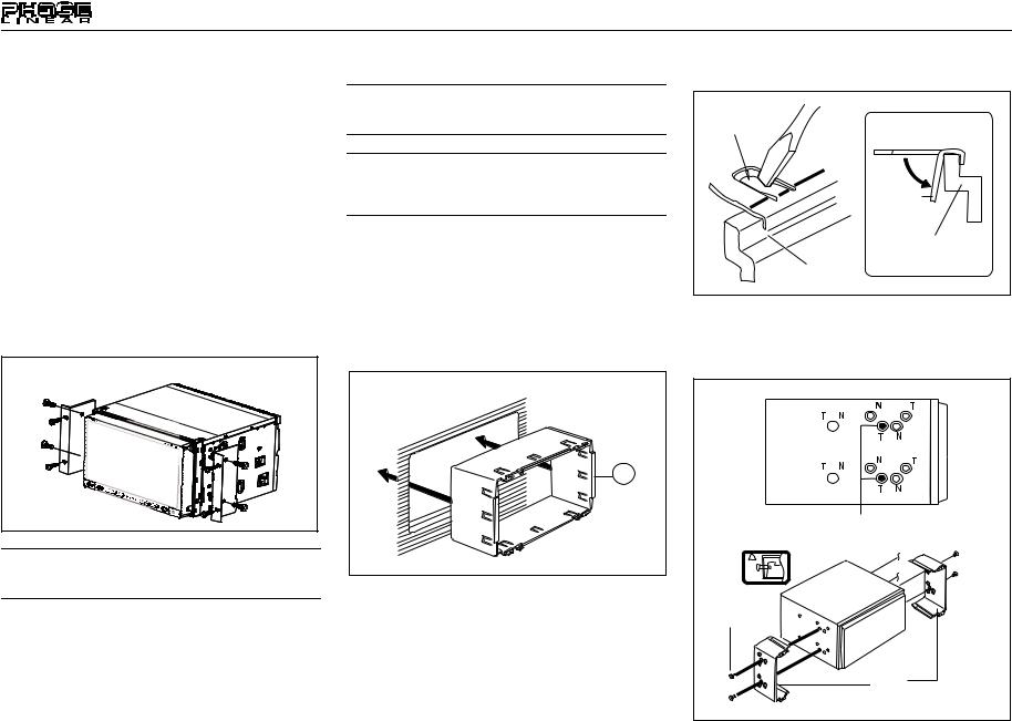
2.Remove the four screws at the front of the radio that attach the mounting sleeve to the radio chassis (two at the top and two at the bottom). Remove the Half Sleeve.
3.Remove the factory mounting brackets and hardware from the existing radio and attach them to the new radio.
ISO INSTALLATION |
CAUTION: Do not exceed M5 X 6MM screw size. Longer screws may touch and damage components inside the chassis.
4.Place the radio in front of the dashboard opening so the wiring can be brought through the dash. Follow the wiring diagram carefully and make certain all connections are secure and insulated with wire nuts or electrical tape. After completing the wiring connections, plug the ISO connectors into the mating sockets on the rear of the chassis. Turn the unit on to confirm operation (vehicle ignition switch must be “on”). If the unit does not operate, re-check all wiring until the problem is corrected.
5.Mount the new radio assembly to the dashboard or center console using the reverse procedure in step 1.
CAUTION: For proper operation of the CD player, the chassis must be mounted within 30° of horizontal. Make sure the unit is mounted within this limitation.
NOTE: It is the end-users responsibility to install and operate this unit in a manner in accordance with local, state and federal laws. The PARKING BRAKE wire MUST BE CONNECTED as directed in the manual.
Installation Using Mounting Sleeve
1.Press the metal levers on both sides to remove the mounting sleeve from the radio.
2.Install the sleeve.
a.Install adapter if necessary (optional).
b.Install sleeve into adapter or dashboard (use only the supplied screws). Do not force the sleeve into the opening or cause it to bend or bow.
INSTALL HALF SLEEVE
2b
c.Locate the series of bend-tabs along the top, bottom and sides of the mounting sleeve. With the sleeve fully inserted into the dashboard opening, bend as many of the tabs outward as necessary so that the sleeve is firmly secured to the dashboard.
2
TAB
TAB
DASHBOARD
DASHBOARD
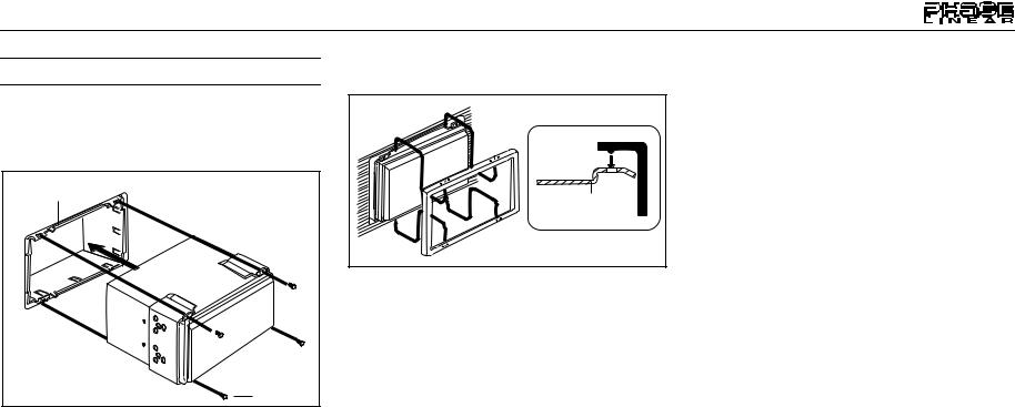
3.Use the M5 x 6 screws (provided) to install the mounting brackets to each side of the radio using the holes indicated below.
Install Bracket Here
Non-Designated
Screw Prohibited
M5X6
SCREW
BRACKET
4.Place the radio in front of the dashboard opening so the wiring can be brought through the mounting sleeve.
UV8020
CAUTION! Be careful not to damage the car wiring.
5.Complete wiring as illustrated in the wiring diagram on page 3. Once the wiring is complete, reconnect the battery negative terminal. If there is no ACC available, connect the ACC lead to the power supply with a switch.
MOUNTING SLEEVE |
M3x4 |
SCREW |
After completing the wiring connections, turn the unit on to confirm operation (ignition switch must be on). If unit does not operate, recheck all wiring until problem is corrected. Once proper operation is achieved, turn off the ignition switch and proceed with final mounting of the chassis.
1.Connect wiring adapter to existing wiring harness.
2.Connect antenna lead.
3.Carefully slide the radio into the sleeve, making sure it is right-side-up, until it is fully seated and the spring clips lock it into place.
Using the Cosmetic Trim Ring
Two cosmetic trim rings are packaged with the UV8020 for installation flexibility. The UV8020 will fit into most import dashes with little or no modification to the dash board/cavity. Some US domestic vehicle dashes will accept a Double-DIN chassis, but there is usually a small gap between the radio and dash piece after installation is complete. In this case, use the appropriate trim ring to conceal any gaps that may be present.
The 4 tabs on the trim ring will snap into four holes on top and bottom of the mounting sleeve.
TRIM RING |
OPTIONAL |
MOUNTING |
TRIM RING |
SLEEVE |
Replacing the Fuse
The fuse is located next to the wiring harness. When replacing the fuse, use a new 15A replacement fuse. Using a fuse with an improper rating could damage the unit and cause a fire.
3

UV8020
WIRING DIAGRAM
Auto Antenna
)-GREEN/BLACK( |
GREEN(+) WHITE/BLACK(-) |
WHITE(+)FRONTL |
|
)-GREY/BLACK(FRONTR |
GREY(+) |
PURPLE(+) |
)-PURPLE/BLACK( |
REARL |
|
|
|
|
|
|
REARR |
|
|
|
|
|
|
|
|
FILTER/FUSE |
(15A) |
PINK(-) |
PRKSW |
|
|
|
ANT.CONT |
|
|
|
BLUE/WHITE |
|
|
|
GND |
ACC |
RED |
YELLOW |
BLACK |
|
|
BATT |
|
SWITCH |
|
|
|
IGNITION |
|
+ |
- |
|
|
BATTERY
(+) |
REVERSE |
SUBWOOFER |
REAR R |
REAR L |
FRONT R |
FRONT L |
OUT1 |
OUT2 |
CAMERA |
GREEN/WHITE |
YELLOW |
YELLOW |
YELLOW |
||||||
|
|
|
|
|
|
|
VIDEO |
VIDEO |
|
RearVideo1 |
2 |
|
RearVideo |
Video Camera |
|
|
|
Rear View |
BLUE |
RED |
WHITE |
RED |
WHITE |
External Power Amplifier
4
UV8020
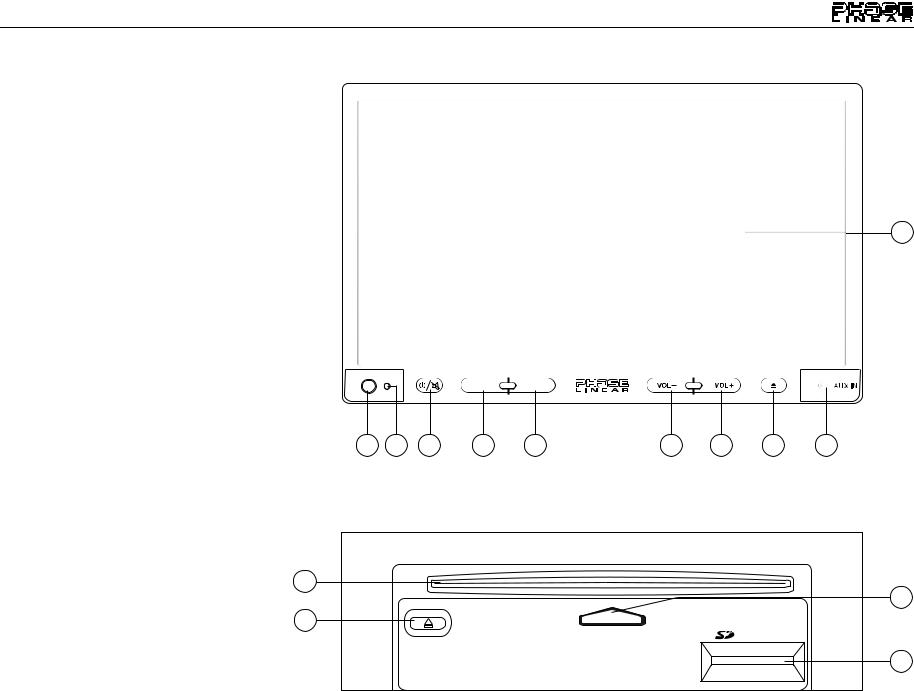
CONTROLS AND INDICATORS
1. POWER/MUTE
Press to turn the unit on. Press and hold to turn the unit off.
When on, press to silence the receiver. Press again to resume the previous volume level.
2. SRC
Press to select playing mode (SD, AV IN, DISC, Tuner).
3. VOL–
Press to adjust the volume lower.
4. VOL+
Press to adjust the volume higher.
5. OPEN/EJECT
Press to activate the automatic mechanical system and move the TFT monitor down to reveal the CD and SD Card slots. Press again to close the TFT.
Press and hold to view the on-screen tilt controls.
6. DIM
Press repeatedly to dim the TFT screen or return to the brightness setting specified in the Setup menu.
7.A/V AUX IN
8.IR Remote Control Receiver
9.RESET
Press to reset system settings to factory default.
10.TFT Display
11.Disc Slot
12.Disc Slot Indicator
13.EJECT Disc
14.SD Card Slot
11
13
UV8020 |
MultiMedia Receiver |
10
SRC |
DIM |
8 9 1 2 6 3 4 5 7
12
DISC IN
LABEL SIDE UP
EJECT
14
5
 Loading...