


VR209TP

VR209TP
TOUCH PANEL MOBILE AUDIO AND OBSERVATION SYSTEM
Installation and Operation Manual

SAFETY INFORMATION
When Driving
Keep the volume level Iow enough to be aware of the road and traffic conditions.
Protect from Water
Do not expose the product to water, as this can cause electrical shorts, fire or other damage.
Protect from High Temperatures
Exposure to direct sunlight for an extended period of time can produce very high temperatures
inside your vehicle. Give the interior a chance to cool down before starting playback.
Do not mount radio within close proximity of engine compartment.
Use the Proper Power Supply
This product is designed to operate with a 12 volt DC negative ground battery system.
Protect the Disc Mechanism
Avoid inserting any foreign objects into the disc slot. Misuse may cause malfunction or permanent
damage due to the precise mechanism of this unit.
CAUTION:
THIS MOBILE CD PLAYER IS A CLASS I LASER PRODUCT. THIS UNIT USES A VISIBLE/
INVISIBLE LASER BEAM WHICH COULD CAUSE HAZARDOUS RADIATION IF EXPOSED
DIRECTLY. BE SURE TO OPERATE THE MOBILE CD PLAYER AS INSTRUCTED.
USE OF CONTROLS OR ADJUSTMENTS OR PERFORMANCE OR PROCEDURES OTHER
THAN THOSE SPECIFIED HEREIN MAY RESULT IN HAZARDOUS RADIATION EXPOSURE.
DO NOT OPEN COVERS AND DO NOT REPAIR BY YOURSELF. PLEASE REFER SERVICING
TO A QUALIFIED TECHNICIAN.
WAR NING:
• TO REDUCE THE RISK OF FIRE OR ELECTRIC SHOCK, DO NOT EXPOSE THIS
EQUIPMENT TO WATER.
• TO REDUCE THE RISK OF FIRE OR ELECTRIC SHOCK AND INTERFERENCE, USE ONLY
THE RECOMMENDED ACCESSORIES.
VR209TP
2
VR209TP
DISC NOTES
Depending on the recording status, conditions of the disc, and the equipment used for recording,
some CD-Rs/CD-RWs may not play on this unit. For more reliable playback, please adhere to the
following recommendations:
• Use CD-RWs with speed 1x to 4x and write with speed 1x to 2x.
• Use CD-Rs with speed 1x to 8x and write with speed 1x to 2x.
• Do not play a CD-RW which has been written more than 5 times.
Compatible Disc Types
Table 1: General Disc Information
NOTE: A disc may become scratched (although not enough to make it unusable) depending
on how you handle it and other conditions in the usage environment. These scratches are
not an indication of a problem with the player.
Disc Type Logo
Audio CD 12 cm single side 74 minutes
RECORDABLE
NOTE: CD-R and CD-RW discs will not play unless the recording session is closed and the
CD is finalized.
REWRITABLE
Diameter/
Playable Sides
Playback Time
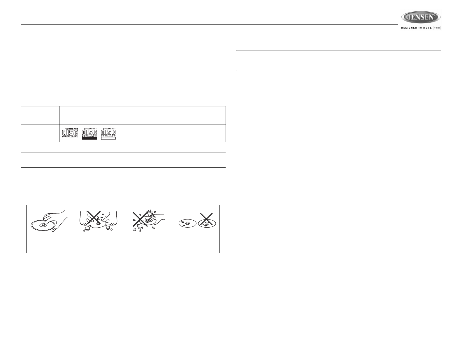
Disc Maintenance
• A dirty or defective disc may cause sound dropouts while playing. Before playing, wipe the disc
using a clean cloth, working from the center hole towards the outside edge. Never use
benzene, thinners, cleaning fluids, anti-static liquids or any other solvent.
Insert label
side up.
• Be sure to use only round CDs for this unit and do not use any special shape CDs. Use of
special shape CDs may cause the unit to malfunction.
• Do not stick paper or tape on the disc. Do not use CDs with labels or stickers attached or that
have sticky residue from removed stickers.
• Do not expose discs to direct sunlight or heat sources such as hot air-ducts, or leave them in a
vehicle parked in direct sunlight where there can be a considerable rise in temperature inside
the vehicle.
Do not bend.
Never touch
the under side
of the disc.
Wipe clean from
the center to the
edge.
3
INSTALLATION
Before You Begin
1. Disconnect Battery
Before you begin, always disconnect the battery negative terminal.
2. Remove Transport Screws and discard.
Important Notes
• Before final installation, test the wiring connections to make sure the unit is connected properly
and the system works.
• Use only the parts included with the unit to ensure proper installation. The use of unauthorized
parts can cause malfunctions.
• Consult with your nearest dealer if installation requires the drilling of holes or other
modifications to your vehicle.
• Install the unit where it does not interfere with driving and cannot injure passengers if there is a
sudden or emergency stop.
• If the installation angle exceeds 30º from horizontal, the unit might not give optimum
performance.
• Avoid installing the unit where it will be subject to high temperatures from direct sunlight, hot
air, or from a heater, or where it would be subject to excessive dust, dirt or vibration.
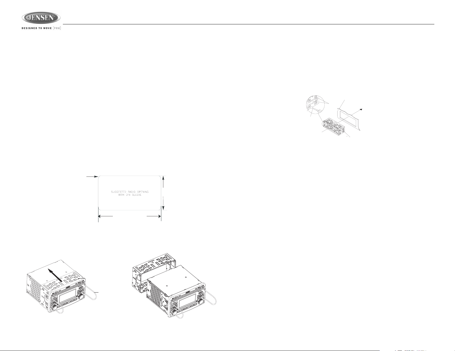
2-DIN Front Mount
This unit can be installed in a dashboard with an opening of the following dimensions:
1/16 inch max
(4 corners)
4 3/8 inches
7 1/4 inches
1. Slide the mounting sleeve off of the chassis if it has not already been removed. If it is locked
into position, use the removal keys (supplied) to disengage it. Insert the keys through the holes
in the front panel as far as they will go, and then slide the sleeve off the back of the unit.
VR209TP
2. Check the dashboard opening size by sliding the mounting sleeve into it. If the opening is not
large enough, carefully cut or file as necessary until the sleeve easily slides into the opening.
Do not force the sleeve into the opening or cause it to bend or bow. Check that there will be
sufficient space behind the dashboard for the radio chassis.
3. Locate the series of bend tabs along the top, bottom and sides of the mounting sleeve. With
the sleeve fully inserted into the dashboard opening, bend as many of the tabs outward as
necessary to firmly secure the sleeve to the dashboard.
DASHBOARD
TABS
SCREWDRIVER
MOUNTING SLEEVE
4. Place the radio in front of the dashboard opening so the wiring can be brought through the
mounting sleeve.
5. Follow the wiring diagram carefully and make certain all connections are secure and insulated
with crimp connectors or electrical tape to ensure proper operation.
6. After completing the wiring connections, reconnect battery and turn the unit on to confirm
operation (vehicle ignition switch must be on). If the unit does not operate, recheck all wiring
until the problem is corrected. Once proper operation is achieved, turn the ignition switch off
and proceed with final mounting of the chassis.
7. Carefully slide the radio into the mounting sleeve making sure it is right-side-up until it is fully
seated and the spring clips lock it into place.
8. Test radio operation by referring to the operating instructions for the unit.
Removing the Unit
To remove the radio after installation:
1. Make sure the ignition is turned off, and then disconnect the cable from the vehicle’s battery
negative (-) terminal.
2. Insert the removal keys straight into the holes on the front of the unit, as far as they will go.
3. Pull the radio straight out.
MOUNTING SLEEVE
REMOVAL KEY
4
VR209TP
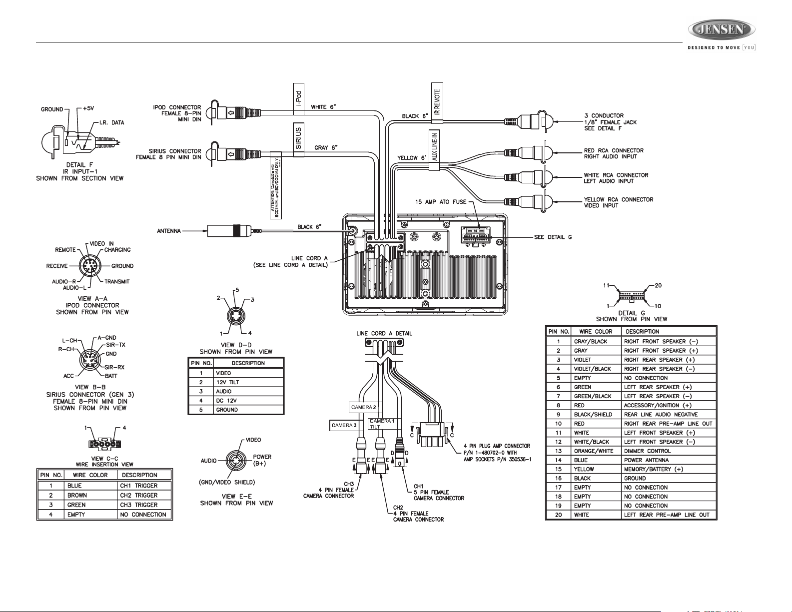
WIRING
5

Recommended Camera Installation Configurations
VR209TP
6
VR209TP
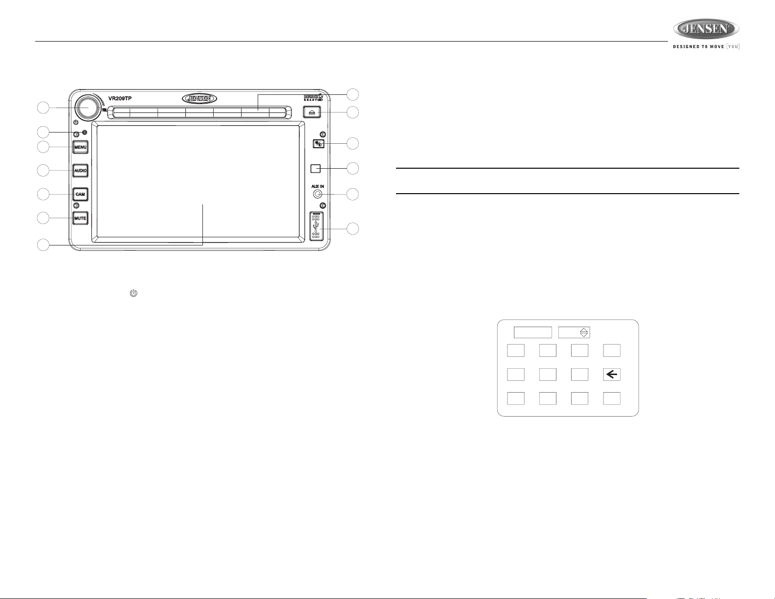
BASIC OPERATION
8
1
2
3
4
5
6
7
Power On/Off
•Press the power VOL/ button (1) to turn the unit on/off.
• Press and hold to turn the touch screen backlighting off when driving at night. Audio playback
is not interrupted.
• Touch any area of the screen to resume the previous display lighting and mode.
Volume Control
• To increase the volume, rotate the VOL control (1) clockwise.
• To decrease the volume, rotate the VOL control counter-clockwise.
• During adjustment, the volume level is displayed in the middle of the display as a horizontal bar
graph with the associated numbered level setting from 0 (full mute) - 40 (0dB, no attenuation).
• The screen will display the volume indicator bar for 3 seconds and then revert to the previous
mode information.
Reset
Use a ball point pin or thin metal object to press the RESET button (2). The reset button should be
activated for the following reasons:
• initial installation of the unit when all wiring is completed
• function buttons do not operate
• error symbol on the display
Menu
• Press the MENU button (3) to access the main User Settings Menu.
• Touch the icon on the display to go to the desired menu for setting adjustment.
• Press and hold the MENU button (3) to access the “System Setup” menu. See “User Settings
Menu” on page 9.
9
10
11
12
13
Camera (CAM)
• Press the CAM button (5) to access camera mode.
• Press and Hold to enter the “Camera Setup” menu. See “Camera Operation” on page 21.
Audio
• Press the AUDIO button (4) to access Audio Mode and select a source for playback.
• Press and hold the AUDIO button to enter the “Audio Setup” menu. See “Source Select Menu”
on page 10.
NOTE: CD/MP3/WMA, iPod or USB mode is inaccessible if the disc is not inserted or the
module is not installed. These buttons will be gray on the screen.
Mute
• Press the MUTE button (6) on the control panel to mute the audio output. “MUTE” will appear
on the display.
• Press MUTE again or touch any area of the screen to restore the audio output to the previous
level.
Adjusting the Clock
The current time is displayed in the top right hand corner of the LCD display. To adjust the clock:
1. Press and hold the MENU button (3) to view the System Setup menu.
2. Touch the “Clock” field to view the clock set screen:
__ __ : __ __
1
4
7
3. Use the on-screen touch pad to enter 4 digits representing the time.
4. Touch the “AM/PM” field to toggle between AM/PM, if necessary.
AM
3
2
5
8
ok
6
9
0
7
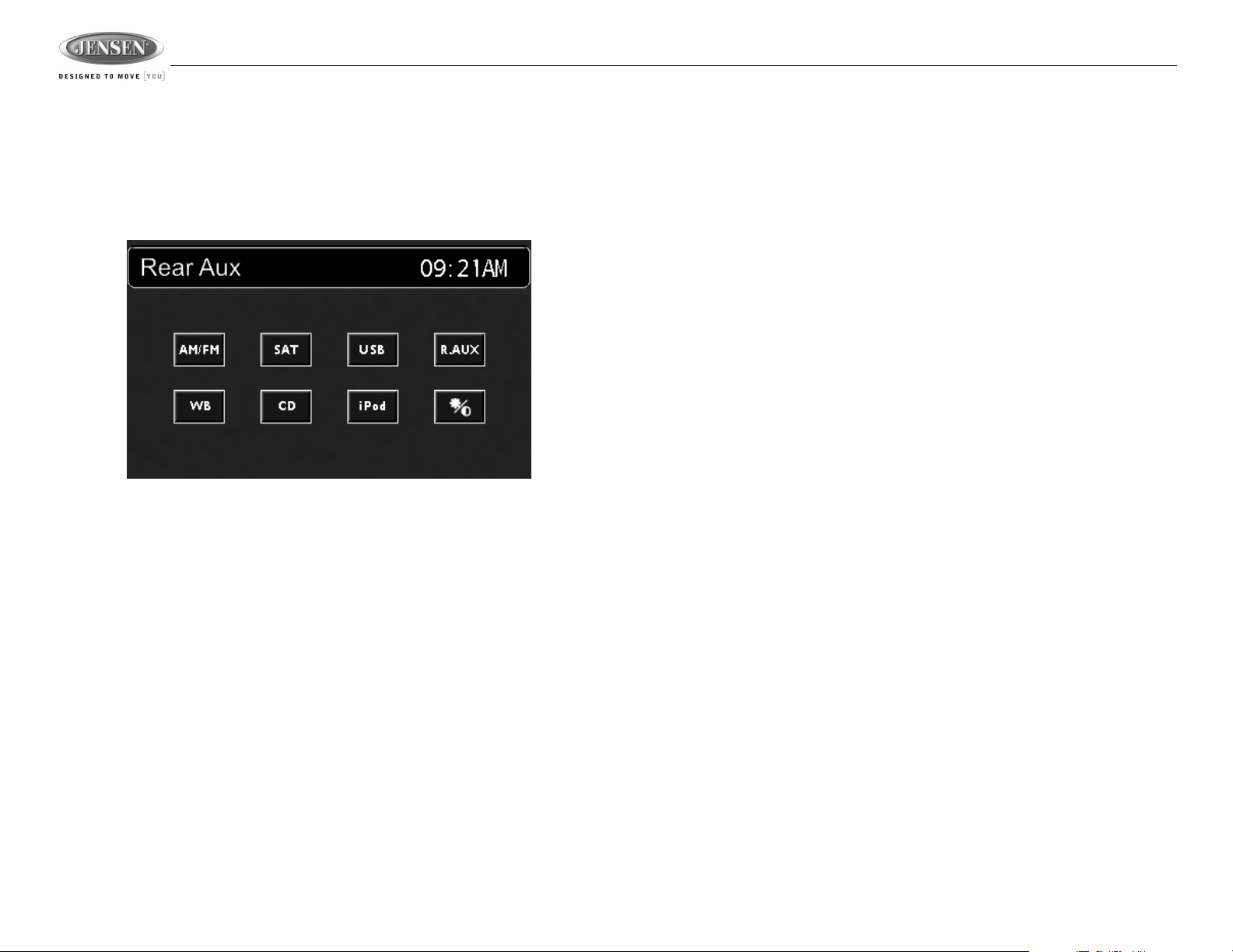
Auxiliary Input
To access an auxiliary device:
1. Connect the portable audio player to the AUX IN connector on the front panel (12) or to the
AUX IN cables on the back of the radio.
2. Touch the AUDIO button on the left side of the screen to select AUX IN mode.
3. Touch the “F.AUX” (front AUX) or “R.AUX” (rear AUX) button to select front or rear AUX in.
Video output is available for the Rear Aux input through video cables at the back of the unit.
VR209TP
Remote Sensor
Point the remote control handset (sold separately) at the remote sensor IR (11) and press the
function keys on the handset to control the system.
Day/Night Backlight
Pressing he DAY/NIGHT button (10) allows you to quickly toggle between preset dimming levels for
night and day viewing of the display.
To set the preset dimming levels:
1. Press and hold the DAY/NIGHT button (10) to enter the “Display Setup” menu.
2. Adjust display backlight intensity using the “Dimming Day” and “Dimming Night” level settings
under the “Display Setup” option on the User Settings Menu.
8
 Loading...