


VR182
MOBILE AUDIO SYSTEM
Installation and Operation Manual

VR182
SAFETY INFORMATION
When Driving
Keep the volume level Iow enough to be aware of the road and traffic conditions.
Protect from Water
Do not expose the product to water, as this can cause electrical shorts, fire or other damage.
Protect from High Temperatures
Exposure to direct sunlight for an extended period of time can produce very high temperatures inside your vehicle. Give the interior a chance to cool down before starting playback.
Do not mount radio within close proximity of engine compartment.
Use the Proper Power Supply
This product is designed to operate with a 12 volt DC negative ground battery system.
Protect the Disc Mechanism
Avoid inserting any foreign objects into the disc slot. Misuse may cause malfunction or permanent damage due to the precise mechanism of this unit.
CAUTION:
THIS MOBILE CD PLAYER IS A CLASS I LASER PRODUCT. THIS UNIT USES A VISIBLE/ INVISIBLE LASER BEAM WHICH COULD CAUSE HAZARDOUS RADIATION IF EXPOSED DIRECTLY. BE SURE TO OPERATE THE MOBILE CD PLAYER AS INSTRUCTED.
USE OF CONTROLS OR ADJUSTMENTS OR PERFORMANCE OR PROCEDURES OTHER THAN THOSE SPECIFIED HEREIN MAY RESULT IN HAZARDOUS RADIATION EXPOSURE.
DO NOT OPEN COVERS AND DO NOT REPAIR BY YOURSELF. PLEASE REFER SERVICING TO A QUALIFIED TECHNICIAN.
WARNING:
•TO REDUCE THE RISK OF FIRE OR ELECTRIC SHOCK, DO NOT EXPOSE THIS EQUIPMENT TO WATER.
•TO REDUCE THE RISK OF FIRE OR ELECTRIC SHOCK AND INTERFERENCE, USE ONLY THE RECOMMENDED ACCESSORIES.
•THIS DEVICE IS INTENDED FOR CONTINUOUS OPERATION.
2
VR182
DISC NOTES
Depending on the recording status, conditions of the disc, and the equipment used for recording, some CD-Rs/CD-RWs may not play on this unit. For more reliable playback, please adhere to the following recommendations:
•Use CD-RWs with speed 1x to 4x and write with speed 1x to 2x.
•Use CD-Rs with speed 1x to 8x and write with speed 1x to 2x.
•Do not play a CD-RW which has been written more than 5 times.
NOTE: A disc may become scratched (although not enough to make it unusable) depending on how you handle it and other conditions in the usage environment. These scratches are not an indication of a problem with the player.
Compatible Disc Types
Table 1: General Disc Information
Disc Type |
|
Logo |
|
Diameter/ |
Playback Time |
|
|
|
Playable Sides |
||||
|
|
|
|
|
|
|
|
|
|
|
|
|
|
|
|
|
|
|
|
|
Audio CD |
|
|
|
|
12 cm single side |
74 minutes |
|
|
|
|
REWRITABLE |
|
|
|
|
RECORDABLE |
|
|
|
|
|
|
|
|
|
|
|
NOTE: CD-R and CD-RW discs will not play unless the recording session is closed and the CD is finalized.
Disc Maintenance
•A dirty or defective disc may cause sound dropouts while playing. Before playing, wipe the disc using a clean cloth, working from the center hole towards the outside edge. Never use benzene, thinners, cleaning fluids, anti-static liquids or any other solvent.
|
|
|
|
|
|
|
|
|
|
Insert label |
Do not bend. |
Never touch |
Wipe clean from |
|
side up. |
|
|
the under side |
the center to the |
|
|
|
of the disc. |
edge. |
|
|
|
|
|
•Be sure to use only round CDs for this unit and do not use any special shape CDs. Use of special shape CDs may cause the unit to malfunction.
•Do not stick paper or tape on the disc. Do not use CDs with labels or stickers attached or that have sticky residue from removed stickers.
•Do not expose discs to direct sunlight or heat sources such as hot air-ducts, or leave them in a vehicle parked in direct sunlight where there can be a considerable rise in temperature inside the vehicle.
3

VR182
INSTALLATION
Before You Begin
1.Disconnect Battery
Before you begin, always disconnect the battery negative terminal.
2.Remove Transport Screws and discard.
Important Notes
•Before final installation, test the wiring connections to make sure the unit is connected properly and the system works.
•Use only the parts included with the unit to ensure proper installation. The use of unauthorized parts can cause malfunctions.
•Consult with your nearest dealer if installation requires the drilling of holes or other modifications to your vehicle.
•Install the unit where it does not interfere with driving and cannot injure passengers if there is a sudden or emergency stop.
•If the installation angle exceeds 30º from horizontal, the unit might not give optimum performance.
•Avoid installing the unit where it will be subject to high temperatures from direct sunlight, hot air, or from a heater, or where it would be subject to excessive dust, dirt or vibration.
DIN Front Mount
This unit can be installed in a dashboard with an opening of the following dimensions:
 MOUNTING SLEEVE
REMOVAL KEY
2.Check the dashboard opening size by sliding the mounting sleeve into it. If the opening is not large enough, carefully cut or file as necessary until the sleeve easily slides into the opening. Do not force the sleeve into the opening or cause it to bend or bow. Check that there will be sufficient space behind the dashboard for the radio chassis.
3.Locate the series of bend tabs along the top, bottom and sides of the mounting sleeve. With the sleeve fully inserted into the dashboard opening, bend as many of the tabs outward as necessary to firmly secure the sleeve to the dashboard.
93mm
 182.6mm
1.Slide the mounting sleeve off of the chassis if it has not already been removed. If it is locked into position, use the removal keys (supplied) to disengage it. Insert the keys through the holes in the front panel as far as they will go, and then slide the sleeve off the back of the unit.
DASHBOARD
TABS
SCREWDRIVER
MOUNTING SLEEVE
4.Place the radio in front of the dashboard opening so the wiring can be brought through the mounting sleeve.
5.Follow the wiring diagram carefully and make certain all connections are secure and insulated with crimp connectors or electrical tape to ensure proper operation.
6.After completing the wiring connections, reconnect battery and turn the unit on to confirm operation (vehicle ignition switch must be on). If the unit does not operate, recheck all wiring until the problem is corrected. Once proper operation is achieved, turn the ignition switch off and proceed with final mounting of the chassis.
7.Carefully slide the radio into the mounting sleeve making sure it is right-side-up until it is fully seated and the spring clips lock it into place.
8.Test radio operation by referring to the operating instructions for the unit.
4
VR182
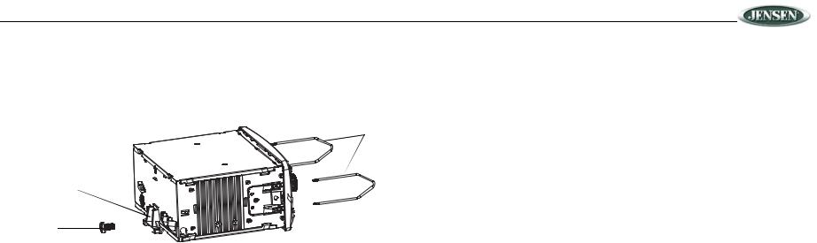
Ford Vehicle Mount
1.Remove the mounting sleeve (see step 1 of “DIN Front Mount” on page 4). The mounting sleeve is not used in this application.
2.Use the supplied mounting screw and the rear installation bracket to secure the unit in place.
REMOVAL KEYS
REAR INSTALLATION
BRACKET
MOUNTING
SCREW
3.Place the radio in front of the dashboard opening so the wiring can be brought through the mounting sleeve.
4.Follow the wiring diagram carefully and make certain all connections are secure and insulated with crimp connectors or electrical tape to ensure proper operation.
5.After completing the wiring connections, reconnect battery and turn the unit on to confirm operation (vehicle ignition switch must be on). If the unit does not operate, recheck all wiring until the problem is corrected. Once proper operation is achieved, turn the ignition switch off.
6.Carefully slide the radio onto the guide rail inside the vehicle dash until it is fully seated and the spring clips lock into place.
7.Test radio operation by referring to the operation section for the unit.
Removing the Unit
To remove the radio after installation:
1.Make sure the ignition is turned off, and then disconnect the cable from the vehicle’s battery negative (-) terminal.
2.Insert the removal keys straight into the holes on the front of the unit, as far as they will go.
3.Pull the radio straight out.
5
 Loading...