


VM8013
Installation and Operation Manual
CH/
DISP
CAT
DIM
SRC  PTY
PTY
BAND
iPod Menu
INT
1 2
RPT RDM
3 4
DN UP
5 6
A/V IN
160
Watts Peak
Watts en Crête Vatios el Máximo
40W x 4

VM8013
TABLE OF CONTENTS |
|
Introduction .............................................................................................. |
1 |
Installation ................................................................................................ |
1 |
Wiring ....................................................................................................... |
3 |
Front Panel Release ................................................................................ |
4 |
Remote Control ........................................................................................ |
5 |
Operation ................................................................................................. |
7 |
Satellite Radio Operation ....................................................................... |
10 |
Radio Operation ..................................................................................... |
12 |
DISC/MP3/WMA Playback ..................................................................... |
14 |
Controlling Your iPod ............................................................................. |
18 |
Setup Menu ............................................................................................ |
19 |
Care and Maintenance ........................................................................... |
20 |
Troubleshooting ..................................................................................... |
21 |
Specifications ......................................................................................... |
22 |
i

VM8013
ii
VM8013
INTRODUCTION
Congratulations on your purchase of the Jensen VM8013 Mobile Multimedia Receiver. It’s a good idea to read all of the instructions before beginning the installation. We recommend having your Jensen VM8013 installed by a reputable installation shop.
INSTALLATION
This unit is designed for installation in cars, trucks and vans with an existing radio opening. In many cases, a special installation kit will be required to mount the radio to the dashboard. These kits are available at electronics supply stores and car stereo specialty shops. Always check the kit application before purchasing to make sure the kit works with your vehicle. If you have trouble locating a kit or need installation assistance, contact Technical Support at 1-800-323-4815 from 9:00am to 6:00pm EST Monday through Friday.
Tools and Supplies
The following tools and supplies are needed to install the radio:
•Torx type, flathead and Philips screwdrivers
•Wire cutters and strippers
•Tools to remove existing radio (screwdriver, socket wrench set or other tools)
•Electrical tape
•Crimping tool
•Volt meter/test light
•Crimp connections
•18 gauge wire for power connections
•16-18 gauge speaker wire
Preparation
1.Disconnect Battery
Before you begin, always disconnect the battery negative terminal.
NOTE: If the VM8013 is to be installed in a car equipped with an onboard drive or navigation computer, do not disconnect the battery cable. If the cable is disconnected, the computer memory may be lost. Under these conditions, use extra caution during installation to avoid causing a short circuit.
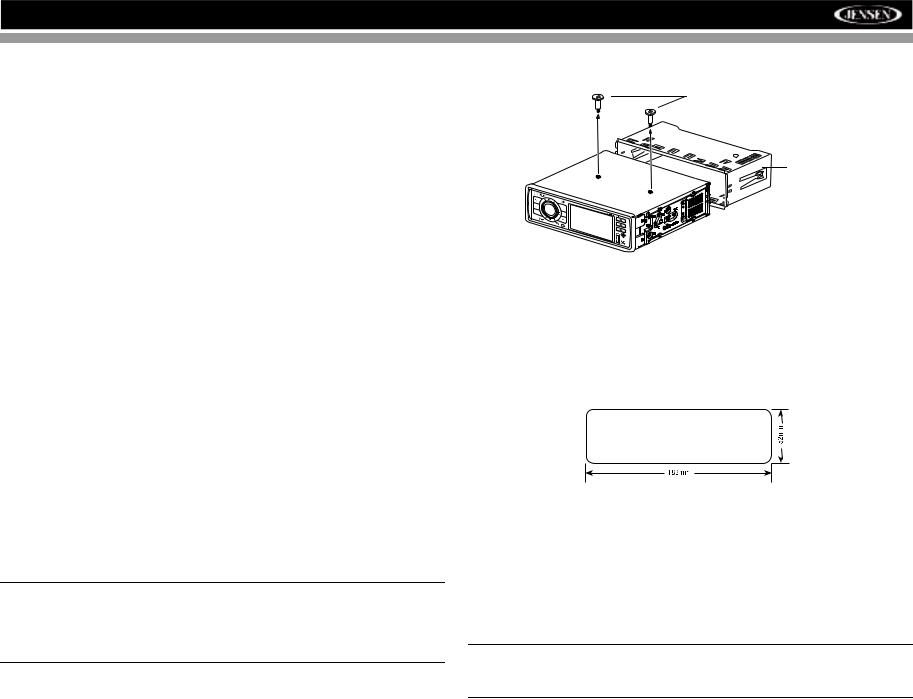
2. Remove Transport Screws
TRANSPORT SCREWS
HALF SLEEVE
1 |
2 |
3 |
4 |
5 |
6 |
3.Remove Radio from Sleeve
Lift latches on both sides of sleeve to remove half-sleeve from radio.
Mounting Sleeve Installation
1.Slide the mounting sleeve off the chassis. If it is locked into position, use the removal tools (supplied) to disengage it.
2.Check the dashboard opening size by sliding the mounting sleeve into it.
If the opening is too small, carefully cut or file as necessary until the sleeve easily slides into the opening. Do not force the sleeve into the opening or cause it to bend or bow. Check for sufficient space behind the dashboard for the radio chassis.
3.Locate the series of bend tabs along the top, bottom, and sides of the mounting sleeve. With the sleeve fully inserted into the dashboard opening, bend as many of the tabs outward as necessary to firmly secure the sleeve to the dashboard.
CAUTION: For proper operation of the DVD player, the chassis must be mounted within 20° of horizontal. Make sure the unit is mounted within this limitation.
1
VM8013
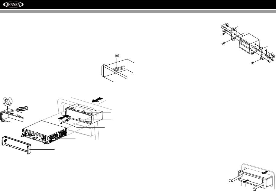
4. Place the radio in front of the dashboard opening so the wiring can be brought through the mounting sleeve. Follow the wiring diagram carefully and make certain all connections are secure and insulated with wire nuts or electrical tape. See “Wiring” on page 3. After completing the wiring connections, turn the unit on to confirm operation (vehicle ignition must be on). If the unit does not operate, re-check all wiring until the problem is corrected.
5. Make sure the radio is right-side up, then
carefully slide the radio into the mounting sleeve until it is fully seated and the spring clips
lock it into place.
6.Secure the rear of the unit to the car body using the mounting bolt and rubber cushion.
7.Test the radio using the “Operation” instructions that follow.
BEND TABS
MOUNTING
SLEEVE
RUBBER
CUSHION
MOUNTING BOLT
RADIO
TRIM RING
Kit Installation
If your vehicle requires the use of an installation kit to mount this radio, follow the instructions included with the installation kit to attach the radio to the mounting plate supplied with the kit.
1.Wire and test the radio as outlined in the Mounting Sleeve Installation instructions.
2.Install the radio/mounting plate assembly to the sub-dashboard according to the instructions in the installation kit.
3.Replace the dashboard trim panel.
ISO Installation
This unit has threaded holes in the chassis side panels which may be used with the original factory mounting brackets of some vehicles to mount the radio to the dashboard. Please consult with your local
car stereo shop for assistance on this type of installation.
1. Remove the existing factory radio from the dashboard or center console mounting. Save all hardware and
brackets as they will be used to mount the new radio.
2.Carefully unsnap the plastic frame from the front of the new radio chassis. Remove and discard the frame.
3.Remove the factory mounting brackets and hardware from the existing radio and attach them to the new radio. Do not exceed M5 x 9mm maximum screw size. Longer screws may damage components inside the chassis.
4.Wire the new radio as outlined in the Mounting Sleeve Installation instructions.
5.Mount the new radio assembly to the dashboard or center console using the reverse procedure of step 1.
Fuses
When replacing a fuse, make sure the new fuse is the correct type and amperage. Using an incorrect fuse could damage the radio.
Reconnect Battery
When wiring is complete, reconnect the battery negative terminal.
Removing the Radio
To remove the radio after installation, first remove the face plate. Next, remove the trim
ring by firmly grasping one side and pulling. Insert the removal keys straight back until they lock, then pull the radio out. If the
removal keys are inserted at an angle, they will not lock properly and will not release the unit.
Technical Assistance
If you require assistance, contact Technical Support at 1-800-323-4815 from 9:00am to 6:00pm EST Monday through Friday.
2
VM8013
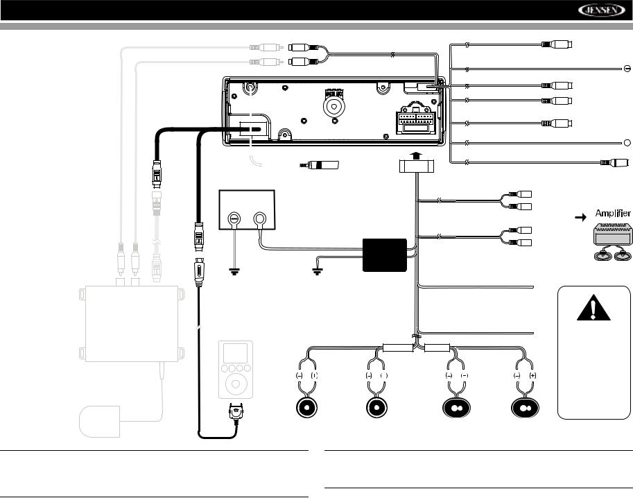
WIRING
SAT BUS
IPOD BUS
Compatible SAT Tuners:
1.XMD1000 (requires XMC or XMDJEN100 Cable Kit)
2.CNP2000UC
3.SC-C1 and SIRJEN2
jLinkiPodCable |
(Included) |
SAT R (Red) |
(Blue) |
|
Subwoofer Out |
||
|
||
SAT L (White) |
Parking/Active Low Level Input (Pink) |
|
|
Camera In |
|
|
(Yellow) |
|
|
Video Out 1 |
|
|
(Yellow) |
|
|
Video Out 2 |
|
|
(Yellow) |
|
|
Fuse (15A) |
|
|
Camera/Active High Level Input (Green/White) |
|
|
+ |
|
Antenna |
SWC (Steering Wheel Control) |
|
|
||
|
(Requires PAC SWI-PS Interface Adapter) |
) |
) |
Battery |
|
|
Connect the yellow wire to the battery |
||||
+ |
||||
- |
( |
or 12 volt power source that is always |
||
( |
||||
|
|
live. This wire MUST be connected |
||
|
|
for the radio to work. |
|
|
|
|
Yellow |
FILTER |
|
|
|
BOX |
||
Black
Chassis Ground
Connect the black wire to the factory ground wire. If a factory ground wire is not provided, locate a clean, unpainted metal part of the dash and secure the ground wire with a "ring" terminal and a sheet metal screw.
iPod |
NOTE: Video playback not supported for all |
|||
(Sold Separately) |
iPods. See iPod section for more information. |
|||
|
White/Black |
|
|
FRONT |
|
White |
Gray/Black |
Gray |
|
|
Stripe |
|
Stripe |
|
Rear Line out |
R (Red) |
Gray |
L (White) |
Front Line out |
R (Red) |
Black |
L (White) |
Power Antenna
Connect to power antenna or amplifier. If not used, tape bare end of wire.
Blue
Accessory/Ignition
Connect to existing radio wire or radio fuse.
|
Red |
REAR |
|
Green/Black |
Green Purple/Black Purple |
Stripe |
Stripe |
IMPORTANT!
The pink parking wire MUST be connected to the switched side of the parking break circuit (the part that becomes grounded when the brake is applied).
Left Speaker |
Right Speaker |
Left Speaker |
Right Speaker |
(Front) |
(Front) |
(Rear) |
(Rear) |
NOTE: The amplifier in this radio is only designed for use with four speakers. Never combine (bridge) outputs for use with two speakers. Never ground negative speaker leads to chassis ground. Failure to wire exactly as shown may cause electrical damage to the radio.
NOTE: Only connect speakers with a nominal impedance of 4 ohms. Speakers with a load impedance less than 4 ohms could damage the unit.
3

VM8013
FRONT PANEL RELEASE
The front panel release button (4) releases the mechanism that holds the front panel to the chassis.
Detaching the Front Panel
To detach the front panel, perform the following steps:
1.Press the power button (1) to turn the unit off.
2.Press the front panel release button to flip the panel down.
3.Grasp the right side to release the front panel and then pull it at an angle to remove the right side from the chassis.
4.Store the front panel it in the supplied carrying case to protect it from dirt and damage and take it with you to prevent theft.
Re-attaching the Front Panel
Before re-attaching the front panel, make sure the electrical terminals on the back of the panel are free of dust and dirt, as debris could cause intermittent operation or other malfunctions.
To re-attach the front panel:
1.With the panel laying flat (in the “open” position), insert the left side of the panel in place until correctly engaged.
2.Gently press the right side of the panel until the mechanism locks it into place.
3.Lift upward to close the panel.
4
VM8013
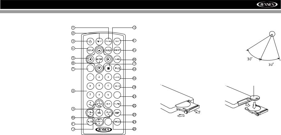
REMOTE CONTROL
The remote control will allow you to control the advanced functions of the VM8013.
CLEAR
Operating Range |
|
The remote control sensor (19) is located near |
REMOTE SENSOR |
the bottom of the front panel, left of the LCD |
|
screen. The remote control can operate within |
|
a distance of 3~5m. |
|
Replacing the Battery
When the range of operation of the remote control becomes short or stops functioning,
replace the battery with a new lithium battery.
Be sure to observe the proper polarity, as indicated below.
(CR 2025)
RDM
1 |
2 |
BAND
5
 Loading...