


®
How to Install and Operate the XA2150 Amplifier
®
POWER |
HIGH |
|
|
INPUT |
|
|
|
|
|
|
LOW |
|
|
L |
R
PASS |
OUTPUT |
|
|
L |
|
R |
|
PROTECT
Welcome!
What you're holding in your hands is no ordinary owner's manual. We've tried to make the instructions in this book clear and easy to follow.
For your Jensen amplifier to work right, it must be installed correctly. This manual will show you how to install your new amplifier like a pro. It's a good idea to read all of these instructions before you begin the installation. Most installations are straightforward and can be handled by a do-it-yourselfer with the right tools, patience, and the ability to follow instructions. But, do-it-yourself installation isn't for everyone. If you still don't feel confident after reading this book, consider turning the installation job over to someone better suited to it.
Warranty Service
If your Jensen amplifier should ever require service, you will need to have the original dated receipt. If you ever need to return the unit for any reason, always include the receipt with the product.
 Technical Assistance
For technical assistance with the operation or installation of the XA2150, call 1-800-323-0221.
Contents |
|
Features........................................ |
2 |
Installation................................... |
2 |
Before You Begin |
|
Installation ..................................... |
2 |
Amplifier Location .......................... |
2 |
Disconnect Battery ........................ |
2 |
• Amplifier Installation Kit ............. |
2 |
Supplies and Tools |
|
Needed .......................................... |
3 |
Routing Wires ................................ |
3 |
• Bigger is Better .......................... |
3 |
Wiring ............................................. |
4 |
Power and Outputs ........................ |
4 |
Power Terminal (BATT +12V) ........ |
4 |
Ground Terminal (GND) ................. |
4 |
Remote Terminal (RMT +12V) ....... |
4 |
Fuses ............................................. |
4 |
Inputs and Controls ....................... |
5 |
Input Wiring.................................... |
5 |
Pass Output ................................... |
5 |
Power Light .................................... |
5 |
Protect Light .................................. |
5 |
Input Level Control ........................ |
6 |
Bass Boost..................................... |
6 |
Crossover ...................................... |
6 |
Speaker Wiring .............................. |
7 |
Testing .......................................... |
9 |
Reconnect Battery ......................... |
9 |
Test Power Wiring .......................... |
9 |
Test Speaker Connections ............ |
9 |
• Dealing with Alternator |
|
Noise .......................................... |
9 |
• Installing in Trunk ..................... |
10 |
• Crimp Connections .................. |
10 |
• Securing Wires ........................ |
10 |
• Speaker and |
|
Power Wires ............................ |
10 |
Troubleshooting ....................... |
11 |
Specifications |
|
and Warranty ............................. |
12 |
®
|
XA2150 |
|
Features |
|
|
|
|
|
The Jensen XA2150 power amplifier is a two- |
• 150 watts RMS bridged into a 4 ohm load |
|
channel 300-watt total system power automotive |
• Bridgeable design to direct full power to one |
|
amplifier. The XA2150 includes: |
speaker |
|
• RCA inputs |
Audio Amplifiers |
|
• High level inputs |
||
|
||
• Continuously variable low pass or high |
Amplification offers two advantages: |
|
pass crossover |
• The XA2150 amplifier can make the sound |
|
• Bass boost feature |
of your receiver fuller and richer, even at low |
|
• Remote turn on/off |
volume levels. |
|
• Electronic protection circuitry to protect the |
• Many automotive receivers provide four to |
|
amplifier from short circuit, DC offset and |
10 watts at maximum power. At 75 watts |
|
thermal overload |
RMS per channel (200 watts bridged), the |
|
• Unique, super-efficient heat sink design |
XA2150 can be played substantially louder, |
|
• 2 x 75 watts RMS per channel (2 x 150 |
permitting the use of more powerful |
|
speakers. |
||
watts peak) |
||
|
||
• Pass through connectors for adding other |
|
|
amps |
|
|
|
|
 Installation
Before You Begin Installation
Before you begin, you will need tools, supplies and adapters. It is best to make sure you have everything you need before you start. There is a list of supplies and tools on the next page.
Amplifier Location
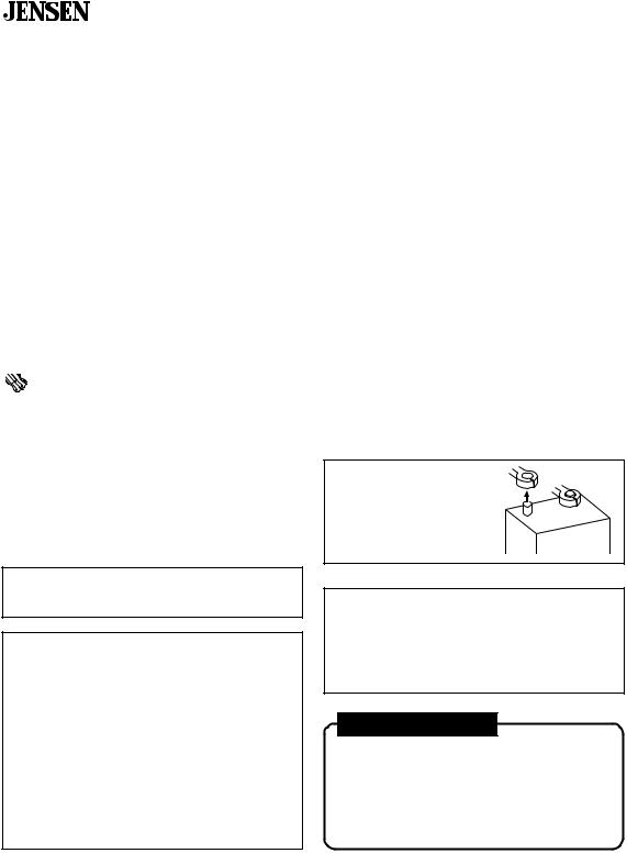
Disconnect Battery
Before you begin, always disconnect the battery negative terminal.
–
+
Important
Allow air circulation around the amplifier.
The XA2150 amplifier’s compact design allows greater flexibility in mounting. It can be mounted under a seat or in the trunk.
When selecting a location, remember that amplifiers generate heat. Select a location where air can circulate around the amplifier. Do not cover the XA2150 with carpets or enclose it behind interior trim panels. Do not mount the amplifier in an inverted or upside down configuration. Every installation will be a bit different based upon vehicle design. Check all locations and placements carefully before making any cuts or connections.
Important
If wiring connections are made wrong, the unit will not operate properly and it could be damaged. Follow the installation instructions carefully, or have the installation handled by an experienced technician.
Professional Tip
Amplifier Installation Kit
Your installation job will be much easier if you purchase an amplifier installation kit. These kits often include low-level RCA cables, extra large power and ground wires, a fuse or circuit breaker and connector for the battery.
2
®
XA2150
Supplies and Tools Needed
Supplies:
•Speaker wire (12 gauge for subwoofers, 16-18 gauge for other speakers)
•Sheet metal type screws for mounting amplifier
•Electrical tape
•Solderless crimp connectors
•1/2" thick plywood or particle board to mount amplifier on
Tools:
•Flat and Phillips screwdrivers
•Wire cutters
•Wire strippers
•Cordless or standard electric drill and drill bit set
•Crimping tool (if using solderless crimp connectors)
•12-volt test light or digital multimeter
•Wire brush or scraper (to remove paint for a good ground connection to vehicle)
•Soldering iron and rosin core solder (if you're going to solder your connections)
Amplifier Installation Kit:
You will need an amplifier installation kit to install your amp properly because it contains all the wire and connectors that you will need to hook up your new amp right the first time. If you want to purchase these items separately you will need the following:
•20-25 feet of 8 gauge wire
•30 amp fuse or circuit breaker (to be hooked up at the battery)
•20 feet of 18 gauge wire for the remote turn-on/ power antenna lead
•RCA cable (for signal input from radio)
–20 feet for trunk installation
–12 feet for under-seat installation
•Two 8 gauge ring terminals (one for the battery connection and the other for the ground connection at the amp). You may need two additional ring terminals if you are using a circuit breaker at the battery.
•Two 8 gauge barrel connectors (you may need these depending on what type of fuse holder you have)
•Two 8 gauge spade terminals (to hook up power at the amp)
•Four 12 gauge spade terminals for subwoofers or 16-18 gauge spade terminals for other speaker connections to amp
•One 18 gauge spade terminal for remote turn-on/ power antenna lead
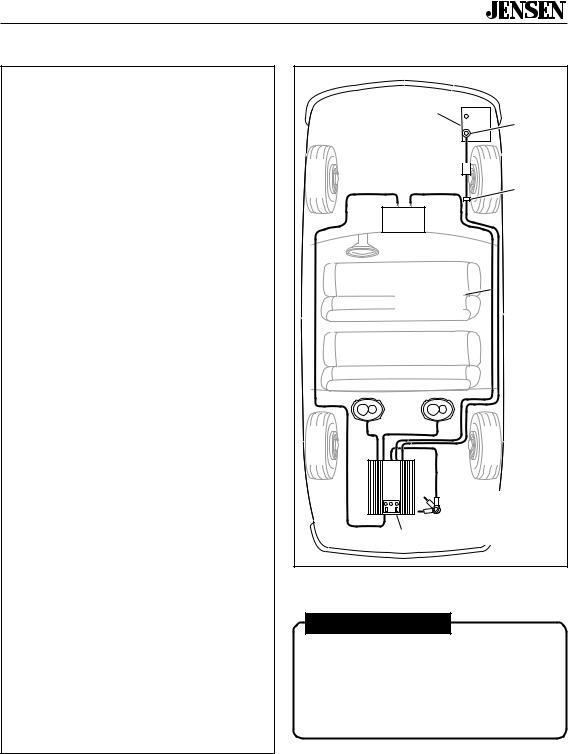
Routing Wires
Battery
Battery
Connector
Fuse or Circuit 
Breaker
Grommet
To prevent damage to power wire
Receiver
Power Wire
 (8 gauge wire or larger)
Power Antenna Turn-on Wire
(18 gauge wire)
 RCA Cables
 Speakers
|
Ground Screw |
|
Drill 1/8" hole in |
|
chassis sheet metal |
Amplifier |
Use the same ground if |
using multiple amplifiers |
Professional Tip
Bigger is better
Stereo installation dealers sell extra thick power and speaker wires to ensure best sound. Look for 8 gauge power wire, especially if you have several amplifiers.
3

®
XA2150
 Wiring
Power and Outputs
FUSE |
+ 12V |
RMT |
GND |
30A |
|
|
|
|
|
POWER |
|
L + |
L – |
R – |
R + |
 SPEAKER
Power Terminal (BATT +12V)
Connect directly to the vehicle battery+ terminal with 8 gauge wire (minimum).
+ 12V RMT GND
|
Not Supplied |
|
Spade |
|
|
Connector |
|
|
30 amp Fuse |
|
|
|
or Circuit Breaker |
|
|
|
|
|
8 Gauge |
Battery |
Install as close |
To Battery+ |
Wire |
|
|||
Terminal |
|
||
Terminal |
to the battery |
|
|
|
|
||
Adapter |
as possible |
|
|
Ground Terminal (GND)
Connect to a good chassis ground. The ground connection should be to clean, unpainted metal to provide a good electrical connection.
+ 12V RMT GND
|
|
Spade |
|
Sheet Metal |
Connector |
Ring |
Screw |
|
(supplied) |
|
|
Connector |
|
|
|
|
|
|
|
8 Gauge |
|
|
Wire |
Drill 1/8" hole |
|
|
in chassis |
|
|
sheet metal |
|
|
Remote Terminal (RMT +12V)
Connect the radio power antenna lead from the receiver to the amplifier REMOTE terminal. This turns the amplifier on whenever the receiver is turned on. If a power antenna lead is not available, connect this wire to the radio or accessory fuse.
+ 12V RMT GND
Spade
Butt Connector Connector
(not supplied)
8 Gauge
Wire
To Receiver
Power
Antenna Lead
Fuses
FUSE
Use only one 30 amp blade-type fuse.
30A
4
 Loading...