


VM9512
Installation and Operation Manual
BAND |
AS |
Multimedia Receiver |
DISP |
CLOSE |
ANGLE / TILT |
PICTURE |
Press Audio |
Enter |
VM9512
DIV ®
video
240 |
Watts Peak |
|
Watts en Crête |
||
|
||
|
Vatios el Máximo |
|
|
60W x 4 |
CONTENTS
Thank you for choosing a Jensen product. We hope you will find the instructions in this owner’s manual clear and easy to follow. If you take a few minutes to look through it, you’ll learn how to use all the features of your new Jensen VM9512 Mobile Multimedia Receiver for maximum enjoyment.
Preparation............................................................................................................................ |
1 |
Installation ............................................................................................................................. |
5 |
Anti-Theft Feature ................................................................................................................. |
6 |
Controls and Indicators ......................................................................................................... |
7 |
Remote Control ..................................................................................................................... |
9 |
Using the TFT Monitor ........................................................................................................ |
12 |
Operating Instructions ......................................................................................................... |
14 |
Multi-ZONE Operation......................................................................................................... |
15 |
Setup Menu......................................................................................................................... |
16 |
Tuner Operation .................................................................................................................. |
18 |
Satellite Radio Operation .................................................................................................... |
20 |
DVD/VCD Video Operation ................................................................................................. |
22 |
DVD/CD Audio Operation ................................................................................................... |
25 |
MP3/WMA/iPod Operation .................................................................................................. |
26 |
Troubleshooting .................................................................................................................. |
29 |
Specifications ...................................................................................................................... |
32 |
i
ii

VM9512
PREPARATION
Congratulations on your purchase of the Jensen VM9512 Mobile Multimedia Receiver.
It’s a good idea to read all of the instructions before beginning the installation. We recommend having your Jensen VM9512 installed by a reputable installation shop.
Features
DVD
•Aspect Ratio - Cinema, Normal and OFF (Standby)
•Fast Forward, Fast Reverse - 2X, 4X and 8X
•Slow Forward, Slow Reverse - 2X, 4X and 8X
•Play, Pause, Stop, Next Chapter and Previous Chapter
•ESP - 2MB Buffer
CD / MP3 / WMA
•ID3 Tag Compatible
•Directory Search (MP3 / WMA Only)
•Direct Track Access via Remote control
•Burn Up To 1500 MP3 and WMA Files onto a DVD+R / RW
•Audible Forward / Reverse Track Search
•Random, Repeat and Intro
•Play, Pause, Stop, Next Track and Previous Track
•ESP - 2MB Buffer
AM-FM
•USA/Europe/Latin America/Asia Frequency Spacing
•30 Station Presets (18 FM, 12 AM)
•Auto Stereo/Mono
•Local/Distance
•Auto Store/Preview Scan
•RDS (Radio Data System)
Sat Radio Ready
•Compatible with XM and Sirius Tuners (Sold Separately)
•Requires XMDJEN100 or JXMC Cables (Sold Separately)
•Satellite Channel Name, Artist, Song and Categories Displayed on TFT Screen
iPod
•jLinkDirect - High Speed Direct Connect Interface to Access iPod Playlists, Artists, Albums, Songs, **Photos and **Video (** Requires Photo or Video iPod)
•Power Management Charges iPod while Connected
•Requires jLinkCable iPod Interface Cable (included)
MediaLink4
•Under Dash Interface Allows Portable Media Devices to be Connected
•MediaLink4 Includes the Following Connectivity:
•USB - Supports Hard Drives and Flash Memory Drives
•LinkDirect 8-pin DIN for iPod
•3.5mm Audio Only Input
•RCA Audio /Video Input
Chassis
•1.0 DIN (Import/ISO-DIN Mountable)
•Motorized/Swivel Flip-Out/Flip-Up LCD Screen
•7" TFT Active Matrix LCD with Anti-Glare Coating
•Screen Tilt/Angle Adjustment
•Heat Management System - Forced-Air Cooling to Keep the Chip Sets Operating at Nominal Temperatures
General
•Bluetooth - Bluetooth hands-free profile for safety / convenience and A2DP profile for streaming music from a PDA / PMP
•Navigation Ready (Nav101 Only)
•38-Key Infrared Remote Control with 5-way Joystick
•Two Composite Video Outputs for Additional Screens
•Compatible with MZ7TFT Rear Seat Monitors with Touch Screen Interface
•Two Audio /Video Auxiliary Inputs
•200-Ohm Preamp Line Output - All Audio Channels
•4VRMS Line Output - All Channels
•Rotary Encoder Audio Control
•Seven-Band EQ with Eight Preset EQ Curves
•Spectrum Analyzer
•Front, Rear, Center and Subwoofer Line Output
•Subwoofer Crossover and Phase Control
•Dolby Digital / Pro-Logic ll
•Programmable Volume Control
•Rear Camera Input (Normal and Mirror Image View)
•Auto TFT Dimmer
•5-Way Joystick
1
VM9512
Optional Equipment
•NAV101
The VM9512 is "navigation ready." Before accessing any navigation features, you must purchase and install the NAV101 module. All installation and operating instructions will be included with the NAV101 navigation module.
Once the NAV101 is connected and operating properly, the NAV source mode will become active. While the NAV101 is not installed, the NAV option appears gray, indicating the function is not available.
•Rear Camera
The VM9512 is "camera ready." Before accessing any camera features, you must purchase and install a rear video camera. Once the rear camera is connected and operating properly, the CAMERA source mode will become active. While the camera is not installed, the CAMERA option appears gray, indicating the function is not available.
•Satellite Radio Tuner
See “Satellite Radio Operation” on page 22.
•iPod
See “MP3/WMA Operation” on page 29.
•Bluetooth Phone
See “Bluetooth Operation” on page 32.
Tools and Supplies
You will need these tools and supplies to install your VM9512:
•Torx type, flat-head and Philips screwdrivers
•Wire cutters and strippers
•Tools to remove existing radio (screwdriver, socket wrench set or other tools)
•Electrical tape
•Crimping tool
•Volt meter/test light
•Crimp connections
•18 gauge wire for power connections
•16 – 18 gauge speaker wire
Disconnecting the Battery
To prevent a short circuit, be sure to turn off the ignition and remove the negative (-) battery cable prior to installation.
NOTE: If the VM9512 is to be installed in a car equipped with an on-board drive or navigation computer, do not disconnect the battery cable. If the cable is disconnected, the computer memory may be lost. Under these conditions, use extra caution during installation to avoid causing a short circuit.
WARNING! Only connect the unit to a12-volt power supply with proper grounding.
WARNING! Never install this unit where operation and viewing could interfere with safe driving conditions.
WARNING! To reduce the risk of a traffic accident (except when using for rear view video camera) never use the video display function while driving the vehicle. This is a violation of federal law.
WARNING! Never disassemble or adjust the unit.
WARNING! To prevent injury from shock or fire, never expose this unit to moisture or water.
WARNING! Never use irregular discs.
WARNING! To prevent damage to the mechanism inside this unit, avoid impact to the TFT monitor.
WARNING! Using an improper fuse may cause damage to the unit and result in a fire.
WARNING! The monitor employs an automatic motorized mechanism. To prevent damage to the core mechanism, please do not push, pull or swivel the monitor manually, other than in the manner explained in “Monitor Left/Right Angle Adjustment” on page 12.
2

VM9512
WIRING DIAGRAM
*See the MediaLink and Satellite Connections diagram for more information about connecting a satellite receiver and an iPod (through the MediaLink).
BLUE
SUB.W
RED
External Power Amplifier
FRONT R
WHITE
FRONT L
RED
REAR R
WHITE
REAR L
MediaLink
Bus
SAT Radio
SAT L
SAT R
AUX IN 1
WHITE |
* Satellite |
|
Receiver |
|
Connections |
RED |
|
YELLOW YELLOW
WHITE WHITE
RED RED
GRAY
CENTER
Antenna Jack
Antenna
Harness Cord
|
Auto antenna control (connect to antenna |
|
|
control lead & power supply of antenna |
|
|
amplifier) |
BLUE |
|
|
|
|
|
ANT.CONT |
|
External power amplifier control |
BLUE/WHITE |
|
|
|
|
|
P.CONT |
|
Car Phone |
|
Car |
Mute (leave open if not connected) |
BROWN |
|
||
MUTE
AUX IN 2
VIDEO OUT 1
NAV101 Input
VIDEO OUT 2
MZ-TFT
HEADPHONE |
MULTIZONE |
CAMERA
|
|
*MediaLink |
YELLOW |
YELLOW |
|
|
|
External AV System |
WHITE |
WHITE |
|
RED |
RED |
|
YELLOW |
Rear Video 1 |
|
YELLOW |
Rear Video 2 |
|
BLACK |
MZ-TFT Touch Screen |
|
(Sold Separately) |
||
WHITE |
|
|
|
|
WIRELESS HEADPHONE |
RED |
|
(OPTIONAL) |
|
|
|
YELLOW |
Rear View |
|
YELLOW Video Camera |
||
|
|
|
|
PINK |
PRK SW |
PARKING BRAKE |
FRONT L+ |
|
WHITE + |
|
|
||
|
|
|
|
|
||
FRONT L |
WHITE/BLACK - |
|
|
|
|
|
FRONT L- |
|
|
|
REVERSE + |
||
|
|
GREEN/WHITE |
REVERSE + |
|||
|
|
|
|
|
||
FRONT R+ |
|
GREY + |
RED |
|
|
|
FRONT R |
GREY/BLACK - |
|
|
|
||
FRONT R- |
|
|
|
|||
|
|
ACC |
|
|
Ignition Switch |
|
|
|
|
|
ACC |
||
REAR R+ |
|
PURPLE + |
|
BATTERY + |
|
|
REAR R |
PURPLE/BLACK - |
YELLOW |
|
|
||
REAR R- |
|
|
||||
|
|
|
||||
|
|
|
|
|
|
|
|
|
|
BATT |
FUSE (15A) |
|
|
|
|
GREEN + |
|
|
|
|
REAR L+ |
|
|
BATTERY |
|
|
|
REAR L |
GREEN/BLACK - |
BLACK |
|
|
||
REAR L- |
|
|
||||
|
|
|
|
|
|
|
|
|
|
GND |
|
|
|
|
|
|
|
|
Ground |
Battery |
3
VM9512
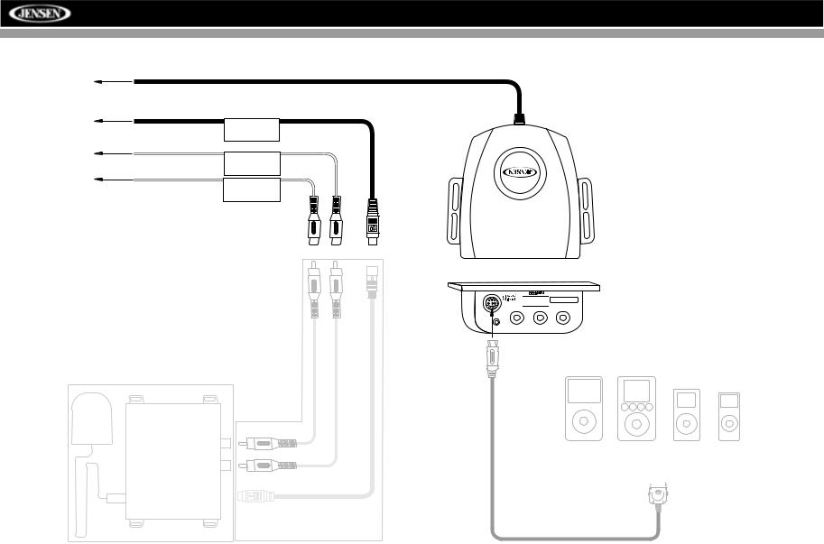
MEDIALINK AND SATELLITE CONNECTIONS
To Head Unit
SAT Radio
SAT L
SAT R
*SAT Cable Kit: JXMC or XMDJEN100 (sold separately)


 MediaLink
**XM or Sirius satellite tuner (sold separately)
3.5mm - Audio VIDEO |
LEFT |
RIGHT |
**
*
iPod Video |
iPod |
|
|
|
iPod Mini iPod Nano |
||||||
|
|
|
|
|
|
|
|
|
|
|
|
|
|
|
|
|
|
|
|
|
|
|
|
|
|
|
|
|
|
|
|
|
|
|
|
|
|
|
|
|
|
|
|
|
|
|
|
|
|
|
|
|
|
|
|
|
|
|
|
|
|
|
|
|
|
|
|
|
|
|
|
jLink iPod Cable
(Included)
4
VM9512
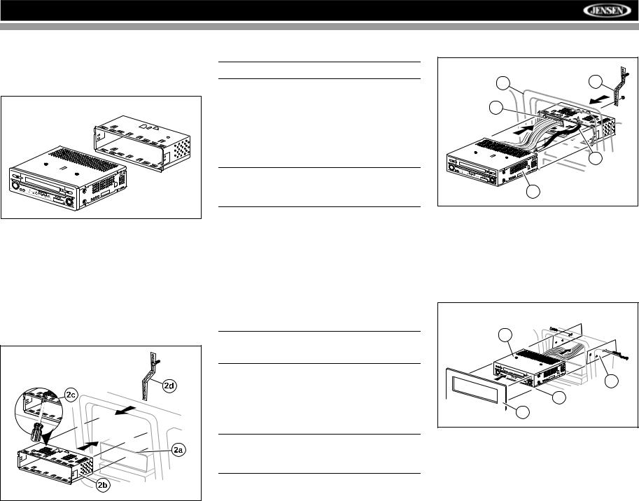
INSTALLATION
Pre-installation
1.Press the metal levers on both sides to remove the halfsleeve from the radio.
PREPARE RADIO |
VM9512 |
2.Install the half-sleeve.
a.Install adapter if necessary (optional).
b.Install half-sleeve into adapter or dashboard (use only the supplied screws). Do not force the sleeve into the opening or cause it to bend or bow.
c.Locate the series of bend-tabs along the top, bottom and sides of the mounting sleeve. With the sleeve fully inserted into the dashboard opening, bend as many of the tabs outward as necessary so that the sleeve is firmly secured to the dashboard.
d.Install support strap to make the unit more stable.
INSTALL HALF SLEEVE |
CAUTION! Be careful not to damage the car wiring.
3.Place the radio in front of the dashboard opening so the wiring can be brought through the mounting sleeve.
Wiring
Complete wiring as illustrated in the wiring diagram on page 3. Once the wiring is complete, reconnect the battery negative terminal. If there is no ACC available, connect the ACC lead to the power supply with a switch.
NOTE: When replacing a fuse, be sure to use correct type and amperage to avoid damaging the radio. The VM9512 uses one 10 amp mini-ATM fuse, located in the black filter box in-line with the main wire harness.
Final Installation
After completing the wiring connections, turn the unit on to confirm operation (ignition switch must be on). If unit does not operate, recheck all wiring until problem is corrected. Once proper operation is achieved, turn off the ignition switch and proceed with final mounting of the chassis.
1.Connect wiring adapter to existing wiring harness.
2.Connect antenna lead.
3.Carefully slide the radio into the half-sleeve, making sure it is right-side-up, until it is fully seated and the spring clips lock it into place.
NOTE: For proper operation of the CD/DVD player, the chassis must be mounted within 20° of horizontal. Make sure the unit is mounted within this limitation.
4.Attach one end of the perforated support strap (supplied) to the screw stud on the rear of the chassis using the hex nut provided. Fasten the other end of the perforated strap to a secure part of the dashboard either above or below the radio using the screw and hex nut provided. Bend the strap to position it as necessary.
CAUTION! The rear of the radio must be supported with the strap to prevent damage to the dashboard from the weight of the radio or improper operation due to vibration.
5.Replace any items you removed from the dashboard.
FINAL INSTALLATION |
|
5 |
4 |
|
|
1 |
|
|
2 |
|
3 |
Final ISO-DIN Installation
1.Remove trim ring.
2.Mount factory brackets on new radio using existing screws from old radio.
3.Slide radio chassis into dash opening and secure.
4.Reinstall dash panel.
FINAL ISO-DIN INSTALLATION |
3 |
2 |
1 |
4 |
5

VM9512
ANTI-THEFT FEATURE
The VM9512 is equipped with an anti-theft feature requiring the user to enter a password upon initial power on.
The default user password is 012345 (6 digits).
To change the anti-theft and RATINGS protection password, perform the following steps:
1.Press the SETUP button (31) on the remote control or
touch the  button on the screen to enter the “SETUP” menu.
2.Touch RATING to view the “RATING” sub-menu. The small "lock" icon will be “unlocked”.
3.Enter a new 6-digit password and press ENTER.
The "lock" icon will lock and the new anti-theft password will be set, as well as the password for RATING protection (see “Rating Sub-menu Features” on
page 18).
NOTE: If you forget your password, contact Customer
Service at 1-800-323-4815 for assistance.
6
VM9512
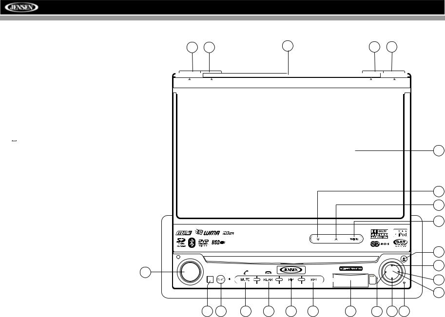
CONTROLS AND INDICATORS
Button Operation
1. OPEN/CLOSE
Press to activate the automatic mechanical system and move the TFT monitor into viewing position. Press again to close the TFT.
2. DISP
With the TFT monitor open, press to cycle through information available on the TFT screen.
4 |
3 |
7 |
2 |
1 |
BAND |
AS |
DISP |
OPEN |
With the TFT monitor closed, press and hold to view the clock.
In DVD Mode, press to view the top and bottom information |
|
bars. Press again to turn “Display Off”. |
5 |
3. AS
Press to automatically store the first six strong stations in preset memory. Applies to current band only.
4. BAND
 Press Audio
VM9512
16
Enter
15
14
13
Press the BAND button to change the AM, FM or SAT band.
5. AUDIO
Rotate to adjust the volume. Press to enter and/or confirm audio settings.
6. SRC
Press to select playing mode.
7.LCD Display
8.MUTE
Press to silence the receiver. Press again to resume previous volume level.
BT Mode: Answer Bluetooth call.
9 |
6 |
8 |
18 |
20 |
19 |
21 |
10 |
11 |
12 |
11. (down joystick)
DVD/Disc Mode: Press once for slow forward/slow reverse. TUNER Mode: Press to go down one frequency step. MENU Mode: Press once to move the cursor down.
12. Reset
Press to reset system settings to factory default (except the password and parental lock setting).
NOTE: The VM9512 features Softmute, which will allow the volume to increase or decrease gradually when the MUTE function is activated or deactivated.
9.IR Remote Control Receiver
10.(left joystick)
DVD/Disc Mode: Press once to play back the previous chapter/track.
TUNER Mode: Press once to auto-search for the previous available radio station.
MENU Mode: Press once to move the cursor to the left.
7
VM9512
CONTROLS AND INDICATORS
13.Pause/Play/Enter
Press to pause or resume playback or to confirm current selection.
14. (right joystick)
DVD/Disc Mode: Press once to enter the next chapter or track.
TUNER Mode: Press once to auto-search the next available radio station.
MENU Mode: Press once to move the cursor to the right.
15. (up joystick)
DVD/Disc Mode: Press once for fast forward/fast reverse. TUNER Mode: Press to go up one frequency step. MENU Mode: Press once to move the cursor up.
16. (  )
)
Press once for disc insertion/ejection.
Press and hold to reset core mechanism position.
17.TFT Display
18.REAR
4 |
3 |
7 |
2 |
1 |
BAND |
AS |
Multimedia Receiver |
DISP |
CLOSE |
17
Select rear zone source. Allows front passengers to listen to the radio while rear passengers listen to a CD, MP3, WMA or watch DVDs.
BT Mode: Disconnect Bluetooth call.
19. RPT
Press to control repeat playback function.
20. PIP
Activate Picture In Picture feature.
21. SD Card Slot
Insert SD card for playback of audio files.
22. WIDE
Press to adjust the display aspect of the picture to one of two settings: CINEMA, NORMAL or Standby (screen off).
NOTE: Only CINEMA and Standby are available for non- 5 video sources.
Press and hold to adjust Brightness and Contrast.
23/24. ANGLE/TILT
Press to activate the tilt function. Press once to adjust the downward tilt angle of the screen one step at a time or press and hold to adjust the angle in a continuous motion up or down.
|
24 |
|
23 |
|
22 |
ANGLE / TILT |
PICTURE |
Press Audio |
16 |
Enter |
|
VM9512 |
15 |
14
13
9 |
6 |
8 |
18 |
20 |
19 |
21 |
10 |
11 |
12 |
8
VM9512
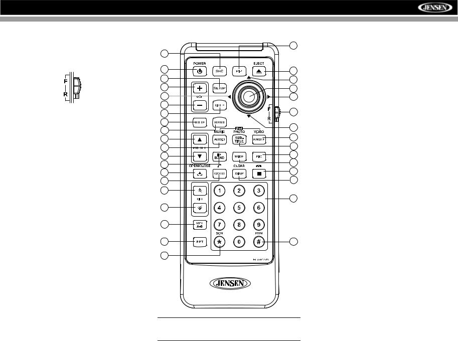
REMOTE CONTROL
The VM9512 Remote controls both the front and rear zones. To switch from front to rear zone, move the F/R switch (32) located on the right side of the controller.
|
30 |
8 |
|
4 |
35 |
|
|
31 |
14 |
16 |
18 |
|
|
17 |
19 |
15 |
|
2 |
32 |
|
|
3 |
|
1 |
22 |
|
|
11 |
13 |
|
|
5 |
9 |
|
|
12 |
24 |
|
|
23 |
28 |
|
|
25 |
20 |
|
|
21 |
10 |
|
|
27 |
|
|
29 |
26 |
|
6 |
|
7 |
33 |
34 |
|
NOTE: Your remote control may differ slightly from the one pictured here. The above diagram is for illustrative purposes only.
9

|
|
|
|
|
|
|
|
|
|
|
|
VM9512 |
|
|
|
|
|
|
|
|
|
|
|
|
|
|
|
|
|
|
|
|
|
|
|
|
|
|
|
|
|
|
|
|
|
|
|
Table 1: Remote Control Functions |
|
|
|
|
|
|
|
|
|
|
|
|
|
|
|
|
|
|
Button |
|
|
|
Function |
|
|
||||
|
|
|
|
|
|
|
|
|
|
|
|
|
|
|
Name |
|
Ref# |
DVD |
VCD |
TUNER |
CD/MP3 |
SATELLITE |
iPod |
||
|
|
|
|
|
|
|
|
|
|
|
|
|
|
|
|
|
|
|
|
|
|
|
|
|
|
MENU |
|
1 |
Enters the main menu of the |
Turns on/off PBC when play- |
|
|
Displays diagnostics screen |
Displays iPod menu |
||||
|
|
|
|
|
|
|
disc |
ing VCD |
|
|
|
|
TITLE |
|
2 |
Enters the title menu of the |
Plays first ten seconds of each |
|
|
Category list in CG mode |
|
||||
|
|
|
|
|
|
|
disc |
chapter/title |
|
|
|
|
MUTE |
|
3 |
Toggles on/off audio output |
Toggles on/off audio output |
Toggles on/off audio output |
Toggles on/off audio output |
Toggles on/off audio output |
Toggles on/off audio output |
||||
|
|
|
|
|
|
|
|
|
|
|
|
|
POWER/ |
|
|
|
4 |
Turns the power on/off |
Turns the power on/off |
Turns the power on/off |
Turns the power on/off |
Turns the power on/off |
Turns the power on/off |
||
|
|
|||||||||||
|
|
|||||||||||
|
|
|
|
|
|
|
|
|
|
|
|
|
AUDIO |
|
5 |
Changes the audio language |
|
|
|
|
Selects iPod Music mode |
||||
|
|
|
|
|
|
|
for disc playback |
|
|
|
|
|
RPT A-B |
|
6 |
Setup to repeat playback from |
Setup to repeat playback from |
|
|
|
|
||||
|
|
|
|
|
|
|
time frame A to time frame B |
time frame A to time frame B |
|
|
|
|
RPT |
|
7 |
Repeats playback of current |
Repeats playback of current |
|
Repeats playback of current |
|
Repeats playback of current |
||||
|
|
|
|
|
|
|
chapter |
chapter |
|
track |
|
track |
SRC |
|
8 |
Selects playing source |
Selects playing source |
Selects playing source |
Selects playing source |
Selects playing source |
Selects playing source |
||||
|
|
|
|
|
|
|
|
|
|
|
|
|
SUBTITLE |
|
9 |
Language selection for subti- |
|
|
|
|
Selects iPod Photo mode |
||||
|
|
|
|
|
|
|
tle |
|
|
|
|
|
DISP/ |
|
10 |
Displays playing information/ |
Displays playing information/ |
Displays audio mode |
Displays audio mode |
Displays audio mode |
Displays audio mode |
||||
CLEAR |
|
|
Delete entry or move back- |
Delete entry or move back- |
Delete entry or move back- |
Delete entry or move back- |
Delete entry or move back- |
Delete entry or move back- |
||||
|
|
|
|
|
|
|
||||||
|
|
|
|
|
|
|
wards to correct error in Direct |
wards to correct error in Direct |
wards to correct error in Direct |
wards to correct error in Direct |
wards to correct error in Direct |
wards to correct error in Direct |
|
|
|
|
|
|
|
Access mode |
Access mode |
Access mode |
Access mode |
Access mode |
Access mode |
PRESET |
|
11 |
Zooms in when playing DVD, |
Zooms in |
Navigates the preset station |
Navigates list window |
Navigates the preset station |
Navigates list window |
||||
|
|
|
|
|
|
|
DivX or Photo |
|
list |
|
list |
|
PRESET |
|
12 |
Zooms out when playing DVD, |
Zooms out |
Navigates the preset station |
Navigates list window |
Navigates the preset station |
Navigates list window |
||||
|
|
|
|
|
|
|
DivX or Photo |
|
list |
|
list |
|
ANGLE |
|
13 |
Plays back disc in different |
Plays back Picture CD with |
Switches MEM keypad off |
|
Switches MEM keypad off |
Selects iPod Video mode |
||||
|
|
|
|
|
|
|
angle (if available) for a scene |
different angle (if available) of |
|
|
|
|
|
|
|
|
|
|
|
|
picture displayed |
|
|
|
|
Joystick /\ |
|
14 |
Fast forwards the disc content |
Fast forwards the disc content |
|
Fast forwards the disc content |
|
Accesses iPod Menu |
||||
|
|
|
|
|
|
|
|
|
|
|
|
|
VOL - |
|
15 |
Decreases volume |
Decreases volume |
Decreases volume |
Decreases volume |
Decreases volume |
Decreases volume |
||||
|
|
|
|
|
|
|
|
|
|
|
|
|
VOL + |
|
16 |
Increases volume |
Increases volume |
Increases volume |
Increases volume |
Increases volume |
Increases volume |
||||
|
|
|
|
|
|
|
|
|
|
|
|
|
Joystick < |
|
17 |
Selects the previous chapter |
Selects the previous chapter |
Searches an available radio |
Selects the previous track for |
Searches an available radio |
Selects prior track |
||||
|
|
|
|
|
|
|
for playback |
for playback |
station by decreasing tuning |
playback |
station by decreasing tuning |
|
|
|
|
|
|
|
|
|
|
frequency |
|
frequency |
|
Joystick |
|
18 |
ENTER, Pauses playback/ |
ENTER, Pauses playback/ |
Auto memory scan |
ENTER, Pauses playback/ |
ENTER, Toggles the on- |
ENTER |
||||
(press) |
|
|
starts playback |
starts playback |
|
starts playback |
screen menu between CAT/ |
|
||||
|
|
|
|
|
|
|
|
|
|
|
CH mode |
|
Joystick > |
|
19 |
Selects the next chapter for |
Selects the next chapter for |
Searches an available radio |
Selects the next track for play- |
Searches an available radio |
Selects the next track for play- |
||||
|
|
|
|
|
|
|
playback |
playback |
station by increasing tuning |
back |
station by increasing tuning |
back |
|
|
|
|
|
|
|
|
|
frequency |
|
frequency |
|
|
|
|
|
|
|
20 |
Stops playback |
Stops playback |
|
Stops playback |
|
|
|
|
|
|
|
|
|
|
|
||||
|
|
|
|
|
|
|
|
|
|
|
|
|
GOTO |
|
21 |
Enters Direct Access mode |
Enters Direct Access mode |
Enters Direct Access mode |
Enters Direct Access mode |
Enters Direct Access mode |
Enters Direct Access mode |
||||
|
|
|
|
|
|
|
|
|
|
|
|
|
Joystick \/ |
|
22 |
Fast reverses the disc content |
Fast reverses the disc content |
|
Fast reverses the disc content |
|
Pauses playback/starts play- |
||||
|
|
|
|
|
|
|
|
|
|
|
|
back |
10
 Loading...