


VM9022HDN
Installation and Operation Manual
video
280 |
Watts Peak |
|
|
|
60w x 4 | 40w x 1 |
CONTENTS
Thank you for choosing a Jensen product. We hope you will find the instructions in this owner’s manual clear and easy to follow. If you take a few minutes to look through it, you’ll learn how to
use all the features of your new Jensen VM9022HDN Mobile Multimedia Receiver for |
|
maximum enjoyment. |
|
VM9022HDN |
|
Preparation............................................................................................................................ |
1 |
Installation ............................................................................................................................. |
5 |
Anti-Theft Feature ................................................................................................................. |
7 |
Controls and Indicators ......................................................................................................... |
8 |
Remote Control ................................................................................................................... |
10 |
Using the TFT Monitor ........................................................................................................ |
13 |
Operating Instructions ......................................................................................................... |
14 |
Multi-ZONE Operation......................................................................................................... |
16 |
Setup Menu......................................................................................................................... |
17 |
Tuner Operation .................................................................................................................. |
20 |
Satellite Radio Operation .................................................................................................... |
22 |
DVD/VCD Video Operation ................................................................................................. |
24 |
DVD/CD Audio Operation ................................................................................................... |
27 |
MP3/WMA Operation .......................................................................................................... |
28 |
iPod Operation .................................................................................................................... |
30 |
Bluetooth Operation ............................................................................................................ |
32 |
Troubleshooting .................................................................................................................. |
35 |
Specifications ...................................................................................................................... |
38 |
Navigation Module |
|
Introduction ......................................................................................................................... |
39 |
Safety Information ............................................................................................................... |
40 |
Getting Started .................................................................................................................... |
41 |
Main Navigation Features ................................................................................................... |
42 |
Choosing and Finding Locations......................................................................................... |
44 |
Navigating ........................................................................................................................... |
48 |
Planning a Route................................................................................................................. |
49 |
Managing your Address Book ............................................................................................. |
50 |
Settings Menu ..................................................................................................................... |
52 |
Navigation Module Troubleshooting.................................................................................... |
55 |
i
ii

VM9022HDN
PREPARATION
Congratulations on your purchase of the Jensen VM9022HDN Mobile Multimedia Receiver.
It’s a good idea to read all of the instructions before beginning the installation. We recommend having your Jensen VM9022HDN installed by a reputable installation shop.
Features
DVD
•Aspect Ratio – Cinema and Normal
•Fast Forward / Reverse – 2X, 4X, 6X and 8X
•Play, Pause, Stop, Next Chapter and Previous Chapter
•ESP – 2MB Buffer
CD / MP3 / WMA
•ID3 Tag Compatible
•Directory Search (MP3 / WMA Only)
•Direct Track Access via Remote control
•Burn up to 1500 MP3 and WMA Files onto a DVD+R / RW
•Audible Forward / Reverse Track Search
•Random, Repeat and Intro
•Play, Pause, Stop, Next Track and Previous Track
•ESP – 2MB Buffer
Tuner
•HD Radio Tuner*
•USA / Europe Frequency Spacing
•24 Station Presets (18 FM / 6 AM)
•Auto Stereo / Mono
•Auto Store
•RDS – Radio Data System
Satellite Radio Ready
•Compatible with XM Tuners (Sold Separately)
•Requires XMDJEN100 or JXMC cables for XMD1000 only (Sold Separately)
•Satellite Channel Name, Artist, Song and Categories displayed on TFT Screen
iPod
•jLinkDirect - High Speed Direct Connect Interface to Access iPod Playlists, Artists, Albums, Songs, Photos** and Video**. (** Requires Gen 5.5 or earlier Photo or Video iPod. iPhone, iPod Touch, iPod Classic, and iPod Nano with Video will only play music files.)
•Power Management Charges iPod while Connected
•Requires jLinkCable iPod Interface Cable (included)
MediaLink4
•Under Dash Interface Allows Portable Media Devices to be Connected
•MediaLink4 Includes the Following Connectivity:
•USB – Supports Flash Memory and Hard Drives with Audio Files
•LinkDirect iPod Connectivity
•3.5mm Audio Only Input
•RCA Audio /Video Input
Chassis
•2.0 DIN (Import / ISO-DIN Mountable)
•Motorized Swing-Down LCD Screen
•6.5" TFT Active Matrix LCD with Anti-Glare Coating
•Screen Tilt / Angle Adjustment
•Heat Management System - Forced Air-Cooling to Keep the Chip-Sets Operating at Nominal Temperatures
General
•Bluetooth – Bluetooth hands-free profile for safety / convenience and A2DP profile for streaming music from a PDA / PMP
•Built-in Navigation System
•38-Key Infrared Remote Control with 5-way Joystick
•Two Composite Video Outputs for Additional Screens
•Compatible with MZ7-TFT Rear Seat Monitors with Touch Screen Interface
•Two Audio /Video Auxiliary Inputs
•200-Ohm Preamp Line Output – All Audio Channels
•4VRMS Line Output – All Channels
•Rotary Encoder Audio Control
•Seven-Band EQ with Eight Preset EQ Curves
•Spectrum Analyzer
•Front, Rear, Center and Subwoofer Line Output
•Built-In Integrated Center Channel Amplifier (40 Watts X 1)
•Subwoofer Crossover and Phase Control
•Dolby Digital / Pro-Logic ll
•Programmable Volume Control
•Rear Camera Input (Normal and Mirror Image View)
•5-Way Joystick
•SWC Interface – Compatible with PAC adapter SWI-PS Steering Wheel Control Interface, sold separately
*HD Radio™ Technology Manufactured Under License From iBiquity Digital Corporation. U.S. and Foreign Patents. HD Radio™ and the HD and HD Radio logos are proprietary trademarks of iBiquity Digital Corporation.
1
VM9022HDN
Optional Equipment
•Rear Camera
The VM9022HDN is "camera ready." Before accessing any camera features, you must purchase and install a rear video camera. Once the rear camera is connected and operating properly, the CAMERA source mode will become active. While the camera is not installed, the CAMERA option appears gray, indicating the function is not available.
•Satellite Radio Tuner
See “Satellite Radio Operation” on page 22.
•jLinkCable and iPod
See “MP3/WMA Operation” on page 28.
•Bluetooth Phone
See “Bluetooth Operation” on page 32.
•3.5mm to 3.5mm Audio Cable
Sold separately at various retailers.
What’s in the Box
1.Left and Right Double DIN Mounting Brackets
2.Double DIN Half Sleeve Install Bracket
3.Remote Control with Battery
4.Rear Support Mounting Strap
5.jLink iPod Cable
6.HD Radio Module
7.HD Radio Module Connecting DIN cable
8.HD Radio Module Mounting Hardware
9.Two Custom Cosmetic Trim Rings
10.Parking Brake Wire
11.MediaLink
12.Screen Cleaning Cloth
13.M5x6 and M3x4 Screws to Mount Radio to Brackets
14.Speaker Output Harness
15.Power Input Harness
16.Center Channel Wire Harness
17.GPS Antenna
18.Back-Up Map Data DVD
19.2GB SD Card
20.Navigation Instructions
Tools and Supplies
You will need these tools and supplies to install your VM9022HDN:
•Torx type, flat-head and Philips screwdrivers
•Wire cutters and strippers
•Tools to remove existing radio (screwdriver, socket wrench set or other tools)
•Electrical tape
•Crimping tool
•Volt meter/test light
•Crimp connections
•18 gauge wire for power connections
•16 – 18 gauge speaker wire
Disconnecting the Battery
To prevent a short circuit, be sure to turn off the ignition and remove the negative (-) battery cable prior to installation.
NOTE: If the VM9022HDN is to be installed in a car equipped with an on-board drive, do not disconnect the battery cable. If the cable is disconnected, the computer memory may be lost. Under these conditions, use extra caution during installation to avoid causing a short circuit.
WARNING! Only connect the unit to a 12-volt power supply with proper grounding.
WARNING! Never install this unit where operation and viewing could interfere with safe driving conditions.
WARNING! To reduce the risk of a traffic accident (except when using for rear view video camera), never use the video display function while driving the vehicle. This is a violation of federal law.
WARNING! Never disassemble or adjust the unit.
WARNING! To prevent injury from shock or fire, never expose this unit to moisture or water.
WARNING! Never use irregular discs.
WARNING! To prevent damage to the mechanism inside this unit, avoid impact to the TFT monitor.
WARNING! Using an improper fuse may cause damage to the unit and result in a fire.
2

VM9022HDN
WIRING DIAGRAM
GPS Antenna
GPS Antenna
MediaLink Cable / BLACK
BLACK |
YELLOW |
VideoViewRearCamera |
MZ7-TFT Touch |
|
|
Screen (Sold |
|
|
Separately) |
|
|
MZ7-TFT |
|
|
CAMERA
External
A/V System
YELLOW |
WHITE |
RED |
|
AUX IN 2 |
|
*NOTE: See the Module Connections Diagram for additional connections through the MediaLink.
YELLOW |
WHITE |
RED |
|
AUX IN 1 |
|
*MediaLink
LREAR
)-GREEN/BLACK(
ConnecttoHDRadioModule(See ModuleConnectionsDiagram) |
|
|
|
|
|
HD RADIO |
|||
|
|
|
||
|
|
|
|
|
|
|
|
|
|
|
|
|
|
|
|
|
|
|
|
|
|
|
|
|
GREEN(+) WHITE/BLACK(-) |
WHITE(+) FRONTL |
GREY/BLACK(-) FRONTR |
GREY(+) |
Sold Separately |
SWC |
RadioSAT |
SATR |
Steering Wheel Control |
|
|
|
(SWC) requires PAC |
|
|
|
SWI-PS Interface Adapter, |
|
|
|
Cell Phone 
RED
|
|
) |
MUTE |
|
|
|
YELLOW |
|
GREEN |
|
BLUE |
|
|
|
* Satellite |
|
|
(-BROWN |
|
|
|
|
|
|
|
|
Receiver |
||||
|
|
|
|
|
|
|
|
|
|
|
|
|
|
|
Connections |
|
)-PURPLE/BLACK( |
SWITCHIGNITION |
|
|
|
FILTER/FUSE (20A) |
BLACK |
/BLACK(BROWN-) |
|
|
|
|
|
GREEN/WHITE |
REVERSE |
PURPLE(+) |
ACC |
RED |
YELLOW |
|
GND |
(+)BROWN |
Auto Antenna |
PRKSW |
|||||||
|
REARR |
|
|
|
|
BATT |
|
|
CENTER |
BLUE |
ANT.CONT |
PINK-)( |
|
(+) |
|
|
|
|
|
|
|
+ |
- |
|
|
|
|
|
|
|
|
|
|
|
|
|
|
BATTERY |
|
|
|
|
|
|
|
|
|
SATL |
CENTER |
SUBWOOFER |
REAR |
RSURROUND |
REAR |
LSURROUND |
FRONT R |
FRONT L |
VIDEOOUT1 |
VIDEOOUT2 |
WHITE |
|
|
|
|
YELLOW |
YELLOW |
|
|
|
|
|
RearVideo1 |
RearVideo2 |
GREY |
BLUE |
RED |
WHITE |
RED |
WHITE |
|
BLUE/WHITE
P.CONT
 External Power Amplifier
HEADPHONE
MULTIZONE
RED |
WHITE |
WIRELESS HEADPHONE (OPTIONAL)
3
VM9022HDN
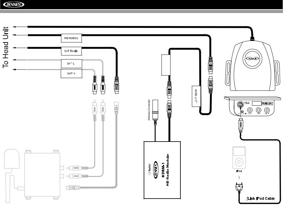
MODULE CONNECTIONS
RADIO HD
MODULE
Compatible SAT Tuners:
1.XMD1000 (requires XMC or XMDJEN100 Cable Kit)
2.CNP2000UC
* Requires Gen 5.5 or
earlier photo or video |
|
iPod. iPhone, iPod |
|
Touch, iPod Classic |
|
and iPod Nano with |
|
video will only play |
|
music files. |
* |
4

VM9022HDN
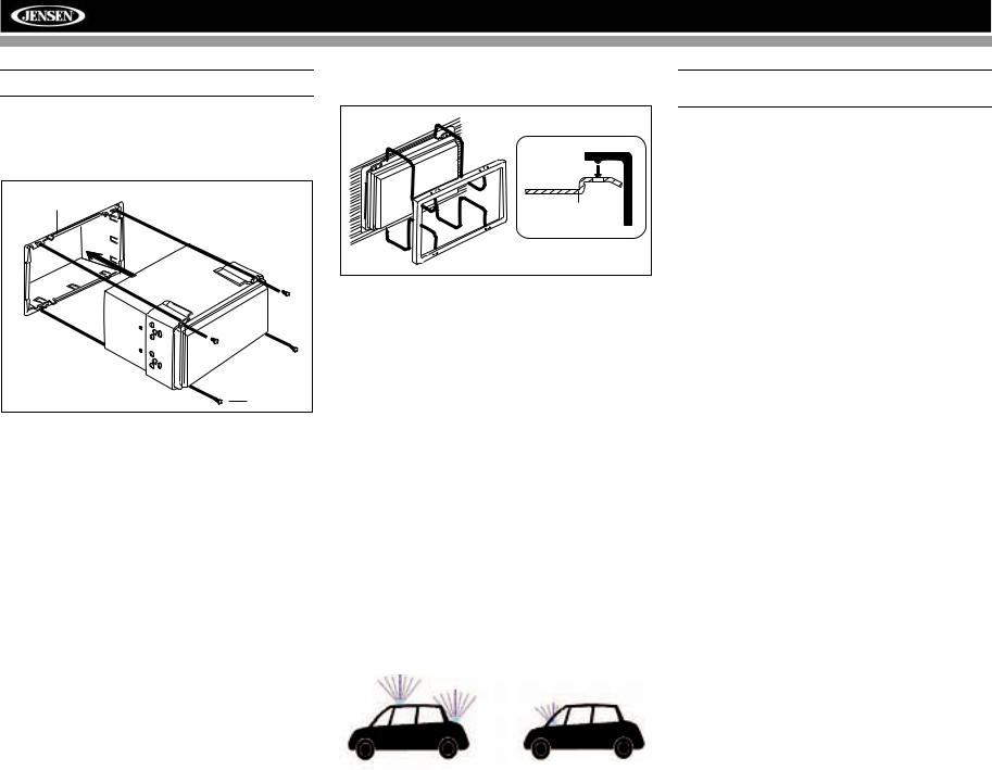
INSTALLATION
ISO DIN Installation
This unit is designed to fit into a 2.0 DIN dashboard opening, found in many imported cars. The unit has threaded holes in the chassis side panels which may be used with the original factory mounting brackets of some Toyota, Nissan, Mitsubishi, Isuzu, Hyundai and Honda vehicles to mount the radio to the dashboard. Please consult with your local car stereo specialty shop for assistance on this type of installation.
1.Remove the existing factory radio from the dashboard or center console mounting. Save all hardware and brackets as they will be used to mount the new radio.
2.Remove the factory mounting brackets and hardware from the existing radio and attach them to the new radio.
ISO INSTALLATION
CAUTION: Do not exceed M5 X 6MM screw size. Longer screws may touch and damage components inside the chassis.
3.Place the radio in front of the dashboard opening so the wiring can be brought through the mounting sleeve. Follow the wiring diagram carefully and make certain all connections are secure and insulated with wire nuts or electrical tape. After completing the wiring connections, plug the ISO connectors into the mating sockets on the rear of the chassis. Turn the unit on to confirm operation (vehicle ignition switch must be “on”). If the unit does not operate, re-check all wiring until the problem is corrected.
4.Mount the new radio assembly to the dashboard or center console using the reverse procedure in step 1.
CAUTION: For proper operation of the CD player, the chassis must be mounted within 30° of horizontal. Make sure the unit is mounted within this limitation.
NOTE: It is the end-users responsibility to install and operate this unit in a manner in accordance with local, state and federal laws. The PARKING BRAKE wire MUST BE CONNECTED as directed in the manual.
CAUTION: Do not block the cooling fan exit. If blocked, the unit may overheat and become damaged.
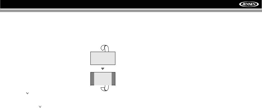
Installation Using Half-Sleeve
1.Press the metal levers on both sides to remove the halfsleeve from the radio.
2.Install the half-sleeve.
a.Install adapter if necessary (optional).
b.Install half-sleeve into adapter or dashboard (use only the supplied screws). Do not force the sleeve into the opening or cause it to bend or bow.
INSTALL HALF SLEEVE
2b
c.Locate the series of bend-tabs along the top, bottom and sides of the mounting sleeve. With the sleeve fully inserted into the dashboard opening, bend as many of the tabs outward as necessary so that the sleeve is firmly secured to the dashboard.
TAB
TAB
DASHBOARD
DASHBOARD
3.Use the M5 x 6 screws (provided) to install the mounting brackets to each side of the radio using the holes indicated below.
Install Bracket Here
Non-Designated
Screw Prohibited
M5X6
SCREW
BRACKET
4.Place the radio in front of the dashboard opening so the wiring can be brought through the mounting sleeve.
5
VM9022HDN
CAUTION! Be careful not to damage the car wiring.
5.Complete wiring as illustrated in the wiring diagram on page 3. Once the wiring is complete, reconnect the battery negative terminal. If there is no ACC available, connect the ACC lead to the power supply with a switch.
MOUNTING SLEEVE |
M3x4 |
SCREW |
After completing the wiring connections, turn the unit on to confirm operation (ignition switch must be on). If unit does not operate, recheck all wiring until problem is corrected. Once proper operation is achieved, turn off the ignition switch and proceed with final mounting of the chassis.
1.Connect wiring adapter to existing wiring harness.
2.Connect antenna lead.
3.Carefully slide the radio into the half-sleeve, making sure it is right-side-up, until it is fully seated and the spring clips lock it into place.
Using the Cosmetic Trim Ring
Two cosmetic trim rings are packaged with the VM9022HDN for installation flexibility. The VM9022HDN will fit into most import dashes with little or no modification to the dashboard or cavity. Some US domestic vehicle dashes will accept a Double-DIN chassis, but there is usually a small gap between the radio and dash piece after installation is complete. In this case, use the appropriate trim ring to conceal any gaps that may be present.
The 4 tabs on the trim ring will snap into four holes on top and bottom of the mounting sleeve.
TRIM RING |
OPTIONAL |
MOUNTING |
TRIM RING |
SLEEVE |
Installing the MediaLink External AV Connector
The MediaLink allows you to connect a variety of external devices, including a VCR, DVD player, portable MP3 player, etc., to your VM9022HDN without removing the radio.
To install the MediaLink, connect it to the AUX-IN cables on the back of the VM9022HDN (see the Wiring Diagram on page 3), and then install the MediaLink in a location convenient for plugging in auxiliary devices.
Installing the Navigation Antenna
The VM9022HDN utilizes an external GPS antenna that must be installed before accessing navigation features.
Since the navigation module uses GPS technology for navigation, proper antenna placement is crucial for optimal performance of the GPS receiver. When using GPS antennas, the antenna plane should be parallel to the geographic horizon. There should be nothing between the antenna and the sky to ensure a direct line-of-sight between the antenna and available satellites.
The preferred antenna location is on the top of the car on the roof or trunk area. When placed on the dashboard, performance may be reduced due to obstruction caused by the window or roof.
NOTE: Do not cut the GPS antenna cable to shorten or lengthen it.
Replacing the Fuse
When replacing the fuse, use a new 20A replacement fuse. Using a fuse with an improper rating could damage the unit and cause a fire.
6
VM9022HDN
ANTI-THEFT FEATURE
The VM9022HDN is equipped with an anti-theft feature requiring the user to enter a password upon initial power on.
3.Touch the keypad icon next to the blue box in the “Password” field to open the on-screen keypad.
Enter Password:
1 |
2 |
3 |
4 |
5 |
6 |
7 |
8 |
9 |
0 |
|
|
Entering the Default Password
The default user password is 012345 (6 digits). Enter the password using the on-screen keypad and then press the Enter (arrow) button. You can also use the remote control keypad to enter the password.
02:40 AM
RADIO |
SETUP |
|
|
|
||
|
|
|
|
|||
General |
Language |
Audio |
Speaker |
Bluetooth |
Back |
|
RDS |
Password |
|
|
1 |
2 |
3 |
Rating |
|
|
||||
Rating |
|
8. Adult |
|
|
|
|
Demo |
|
4 |
5 |
6 |
||
|
|
|
||||
Hardware |
Load Factory |
Reset |
7 |
8 |
9 |
|
|
|
|
|
|||
P.VOL |
|
|
|
0 |
|
|
|
|
|
|
Clear |
|
|
TS Cal |
|
|
|
|
|
|
|
|
|
|
|
|
|
4.Enter a new 6-digit password and press the Enter (arrow) button.
The "lock" icon will now appear closed and the new antitheft password will be set, as well as the password for RATING protection (see “Rating Sub-menu Features” on page 18).
NOTE: If you forget your password, contact Customer Service at 1-800-323-4815 for assistance.
Press the joystick Enter button (18) on the remote control to confirm.
Changing the Password
To change the anti-theft and RATINGS protection password, perform the following steps:
1.Press the SETUP button (31) on the remote control or
touch the  button on the screen to enter the “SETUP” menu.
2.Touch RATING to view the “RATING” sub-menu. An open lock icon to the right of the “Password” field indicates that a user password had not yet been entered.
7
VM9022HDN
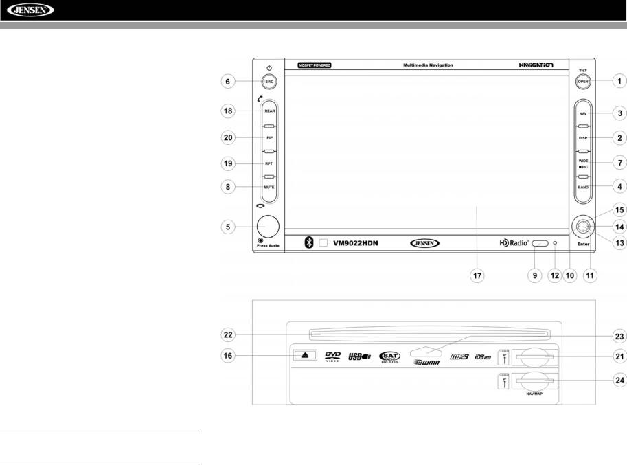
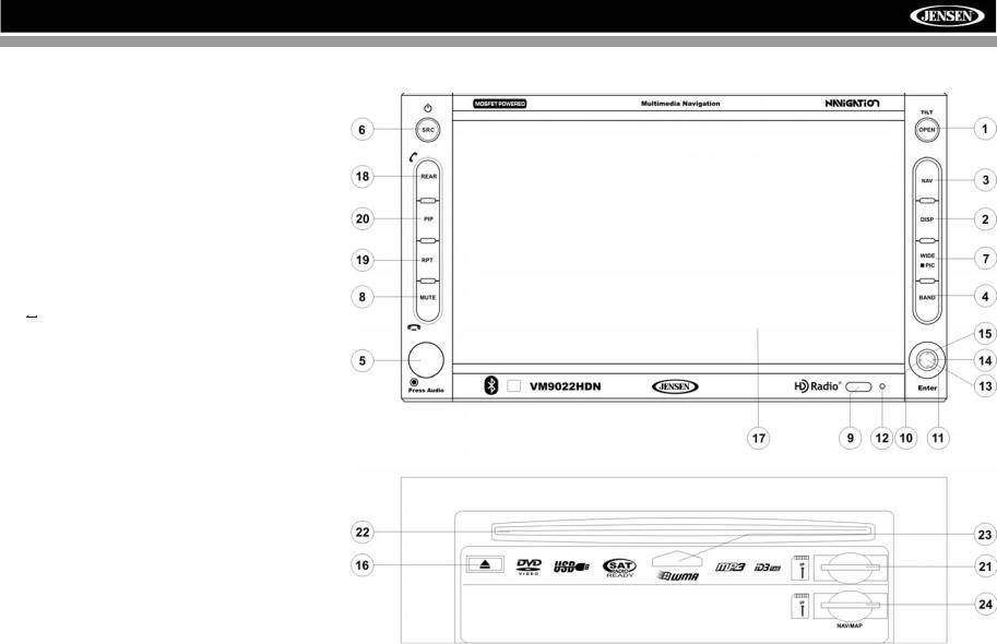
CONTROLS AND INDICATORS
Button Operation
1. OPEN/TILT
Press to activate the automatic mechanical system and move the TFT monitor into viewing position. Press again to close the TFT.
Press and hold to activate the screen tilt function (use the joystick to adjust the angle).
2. DISP
Press to cycle through information available on the TFT screen.
In DVD Mode, press to view the top and bottom information bars. Press again to turn “Display Off”.
3. NAV
Press to access Navigation Mode.
4. BAND
Press the BAND button to change the AM, FM or SAT band.
5. AUDIO
Rotate to adjust the volume. Press to enter and/or confirm audio settings.
6. SRC
Press to select playing mode.
When you change the source during navigation, the voice prompts will still be heard, although the navigation map cannot be seen. (The selected source audio will be muted until the navigation voice prompt command is completed, after which the source audio will resume.)
7. WIDE/PIC
Press to adjust the display aspect of the picture to one of three settings: CINEMA, NORMAL or Standby (screen off). Touch the screen to turn Standy mode off. NOTE: Only CINEMA and Standby are available for non-video sources.
Press and hold to adjust Brightness and Contrast.
8. MUTE
Press to silence the receiver. Press again to resume the previous volume level.
BT Mode: Answer/dial Bluetooth call.
NOTE: The VM9022HDN features Softmute, which will allow the volume to increase or decrease gradually when the MUTE function is activated or deactivated.
9.IR Remote Control Receiver
10.(left joystick)
DVD/Disc Mode: Press once to play back the previous chapter/track.
TUNER Mode: Press once to auto-search for the previous available radio station.
MENU Mode: Press once to move the cursor to the left.
11. (down joystick)
DVD/Disc Mode: Press once for slow forward/slow reverse. TUNER Mode: Press to go down one frequency step. MENU Mode: Press once to move the cursor down.
12. Reset
Press to reset system settings to factory default (except the password and parental lock setting).
8
VM9022HDN
CONTROLS AND INDICATORS
13.Pause/Play/Enter
Press to pause or resume playback or to confirm current selection.
14. (right joystick)
DVD/Disc Mode: Press once to enter the next chapter or track.
TUNER Mode: Press once to auto-search the next available radio station.
MENU Mode: Press once to move the cursor to the right.
15. (up joystick)
DVD/Disc Mode: Press once for fast forward/fast reverse. TUNER Mode: Press to go up one frequency step. MENU Mode: Press once to move the cursor up.
16. ( )
)
Press once for disc insertion/ejection.
Press and hold to reset core mechanism position.
17.TFT Display
18.REAR
Select rear zone source. Allows front passengers to listen to the radio while rear passengers listen to a CD, MP3, WMA or watch DVDs.
BT Mode: Disconnect Bluetooth call.
19. RPT
Press to control repeat playback function.
20. PIP
Press to activate the Picture In Picture function.
21. SD Card Slot
Insert SD card for playback of audio files.
22.Disc Slot
23.Disc Loaded Indicator
24.NAV/MAP SD Card Slot
Insert Jensen Navigation Map Data 2GB SD card (included).
9
VM9022HDN
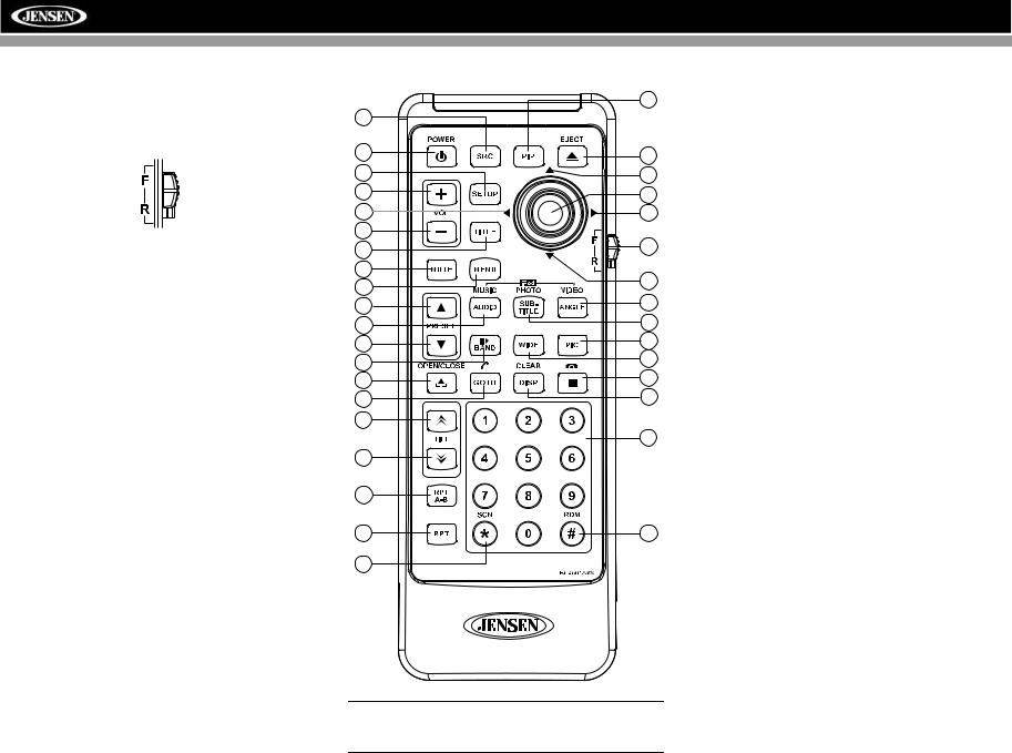
REMOTE CONTROL
The VM9022HDN Remote controls both the front and rear zones. To switch from front to rear zone, move the F/R switch (32) located on the right side of the controller.
|
30 |
8 |
|
4 |
35 |
|
|
31 |
14 |
16 |
18 |
|
|
17 |
19 |
15 |
|
2 |
32 |
|
|
3 |
|
1 |
22 |
|
|
11 |
13 |
|
|
5 |
9 |
|
|
12 |
24 |
|
|
23 |
28 |
|
|
25 |
20 |
|
|
21 |
10 |
|
|
27 |
|
|
29 |
26 |
|
6 |
|
7 |
33 |
34 |
|
NOTE: Your remote control may differ slightly from the one pictured here. The above diagram is for illustrative purposes only.
10

VM9022HDN
Table 1: Remote Control Functions
|
|
Button |
|
|
|
Function |
|
|
||||
|
|
|
|
|
|
|
|
|
|
|
|
|
|
|
Name |
|
Ref# |
DVD |
VCD |
TUNER |
CD/MP3 |
SATELLITE |
iPod |
||
|
|
|
|
|
|
|
|
|
|
|
|
|
|
|
|
|
|
|
|
|
|
|
|
|
|
MENU |
|
1 |
Enters the main menu of the |
Turns on/off PBC when play- |
|
|
Displays diagnostics screen |
Displays iPod menu |
||||
|
|
|
|
|
|
|
disc |
ing VCD |
|
|
|
|
TITLE |
|
2 |
Enters the title menu of the |
Plays first ten seconds of each |
|
|
Category list in CG mode |
|
||||
|
|
|
|
|
|
|
disc |
chapter/title |
|
|
|
|
MUTE |
|
3 |
Toggles on/off audio output |
Toggles on/off audio output |
Toggles on/off audio output |
Toggles on/off audio output |
Toggles on/off audio output |
Toggles on/off audio output |
||||
|
|
|
|
|
|
|
|
|
|
|
|
|
POWER/ |
|
|
|
4 |
Turns the power on/off |
Turns the power on/off |
Turns the power on/off |
Turns the power on/off |
Turns the power on/off |
Turns the power on/off |
||
|
|
|||||||||||
|
|
|||||||||||
|
|
|
|
|
|
|
|
|
|
|
|
|
AUDIO |
|
5 |
Changes the audio language |
|
|
Selects Music mode |
|
Selects iPod Music mode |
||||
|
|
|
|
|
|
|
for disc playback |
|
|
|
|
|
RPT A-B |
|
6 |
Setup to repeat playback from |
Setup to repeat playback from |
|
|
|
|
||||
|
|
|
|
|
|
|
time frame A to time frame B |
time frame A to time frame B |
|
|
|
|
RPT |
|
7 |
Repeats chapter/title |
Repeats track/disc |
|
Repeats track/folder/disc |
|
Repeats playback of current |
||||
|
|
|
|
|
|
|
|
|
|
|
|
track |
SRC |
|
8 |
Selects playing source |
Selects playing source |
Selects playing source |
Selects playing source |
Selects playing source |
Selects playing source |
||||
|
|
|
|
|
|
|
|
|
|
|
|
|
SUBTITLE |
|
9 |
Language selection for subti- |
|
|
Selects Photo mode |
|
Selects iPod Photo mode |
||||
|
|
|
|
|
|
|
tle |
|
|
|
|
|
DISP/ |
|
10 |
Displays playing information/ |
Displays playing information/ |
Displays audio mode |
Displays audio mode |
Displays audio mode |
Displays audio mode |
||||
CLEAR |
|
|
Delete entry or move back- |
Delete entry or move back- |
Delete entry or move back- |
Delete entry or move back- |
Delete entry or move back- |
Delete entry or move back- |
||||
|
|
|
|
|
|
|
||||||
|
|
|
|
|
|
|
wards to correct error in Direct |
wards to correct error in Direct |
wards to correct error in Direct |
wards to correct error in Direct |
wards to correct error in Direct |
wards to correct error in Direct |
|
|
|
|
|
|
|
Access mode |
Access mode |
Access mode |
Access mode |
Access mode |
Access mode |
PRESET |
|
11 |
Zooms in when playing DVD |
Zooms in |
Navigates the preset station |
Navigates list window |
Navigates the preset station |
Navigates list window |
||||
|
|
|
|
|
|
|
or Photo |
|
list |
|
list |
|
PRESET |
|
12 |
Zooms out when playing DVD |
Zooms out |
Navigates the preset station |
Navigates list window |
Navigates the preset station |
Navigates list window |
||||
|
|
|
|
|
|
|
or Photo |
|
list |
|
list |
|
ANGLE |
|
13 |
Plays back disc in different |
Plays back Picture CD with |
Switches MEM keypad off |
Selects Video mode |
Switches MEM keypad off |
Selects iPod Video mode |
||||
|
|
|
|
|
|
|
angle (if available) for a scene |
different angle (if available) of |
|
|
|
|
|
|
|
|
|
|
|
|
picture displayed |
|
|
|
|
Joystick /\ |
|
14 |
Fast forwards the disc content |
Fast forwards the disc content |
|
Fast forwards the disc content |
|
Accesses iPod Menu |
||||
|
|
|
|
|
|
|
|
|
|
|
|
|
VOL - |
|
15 |
Decreases volume |
Decreases volume |
Decreases volume |
Decreases volume |
Decreases volume |
Decreases volume |
||||
|
|
|
|
|
|
|
|
|
|
|
|
|
VOL + |
|
16 |
Increases volume |
Increases volume |
Increases volume |
Increases volume |
Increases volume |
Increases volume |
||||
|
|
|
|
|
|
|
|
|
|
|
|
|
Joystick < |
|
17 |
Selects the previous chapter |
Selects the previous chapter |
Searches an available radio |
Selects the previous track for |
Searches an available radio |
Selects prior track |
||||
|
|
|
|
|
|
|
for playback |
for playback |
station by decreasing tuning |
playback |
station by decreasing tuning |
|
|
|
|
|
|
|
|
|
|
frequency |
|
frequency |
|
Joystick |
|
18 |
ENTER, Pauses playback/ |
ENTER, Pauses playback/ |
Auto memory scan |
ENTER, Pauses playback/ |
ENTER, Toggles the on- |
ENTER |
||||
(press) |
|
|
starts playback |
starts playback |
|
starts playback |
screen menu between CAT/ |
|
||||
|
|
|
|
|
|
|
|
|
|
|
CH mode |
|
Joystick > |
|
19 |
Selects the next chapter for |
Selects the next chapter for |
Searches an available radio |
Selects the next track for play- |
Searches an available radio |
Selects the next track for play- |
||||
|
|
|
|
|
|
|
playback |
playback |
station by increasing tuning |
back |
station by increasing tuning |
back |
|
|
|
|
|
|
|
|
|
frequency |
|
frequency |
|
|
|
|
|
|
|
20 |
Stops playback |
Stops playback |
|
Stops playback |
|
|
|
|
|
|
|
|
|
|
|
||||
|
|
|
|
|
|
|
|
|
|
|
|
|
GOTO |
|
21 |
Enters Direct Access mode |
Enters Direct Access mode |
Enters Direct Access mode |
Enters Direct Access mode |
Enters Direct Access mode |
Enters Direct Access mode |
||||
|
|
|
|
|
|
|
|
|
|
|
|
|
Joystick \/ |
|
22 |
Fast reverses the disc content |
Fast reverses the disc content |
|
Fast reverses the disc content |
|
Pauses playback/starts play- |
||||
|
|
|
|
|
|
|
|
|
|
|
|
back |
11

|
|
|
|
|
|
|
|
VM9022HDN |
|
|
|
|
|
|
|
|
|
|
|
|
|
|
|
|
|
|
|
|
|
|
|
Table 1: Remote Control Functions |
|
|
|
|
|
|
|
|
|
|
|
|
Button |
|
|
|
Function |
|
|
||
|
|
|
|
|
|
|
|
|
Name |
|
Ref# |
DVD |
VCD |
TUNER |
CD/MP3 |
SATELLITE |
iPod |
|
|
|
|
|
|
|
|
|
|
|
|
|
|
|
|
|
|
||>/BAND |
|
23 |
Slow Forward/Slow Reverse |
Slow forward X2, X4, X8 |
Selects AM/FM Band. |
|
Selects SAT1, SAT2 or SAT3 |
|
|
|
|
X2, X4, X8 |
|
|
|
band. |
|
PIC |
|
24 |
Displays Brightness/Contrast |
Displays Brightness/Contrast |
Displays Brightness/Contrast |
Displays Brightness/Contrast |
Displays Brightness/Contrast |
Displays Brightness/Contrast |
|
|
|
Controls |
Controls |
Controls |
Controls |
Controls |
Controls |
OPEN/ |
|
25 |
Opens/closes the TFT monitor |
Opens/closes the TFT monitor |
Opens/closes the TFT monitor |
Opens/closes the TFT monitor |
Opens/closes the TFT monitor |
Opens/Closes the TFT moni- |
CLOSE |
|
|
|
|
|
|
|
tor |
TILT |
|
26 |
Decreases monitor tilt angle |
Decreases monitor tilt angle |
Decreases monitor tilt angle |
Decreases monitor tilt angle |
Decreases monitor tilt angle |
Decreases monitor tilt angle |
|
|
|
|
|
|
|
|
|
TILT |
|
27 |
Increases monitor tilt angle |
Increases monitor tilt angle |
Increases monitor tilt angle |
Increases monitor tilt angle |
Increases monitor tilt angle |
Increases monitor tilt angle |
|
|
|
|
|
|
|
|
|
WIDE |
|
28 |
Selects display mode: CIN- |
Selects display mode: CIN- |
Selects display mode: CIN- |
Selects display mode: CIN- |
Selects display mode: CIN- |
Selects display mode: CIN- |
|
|
|
EMA, NORMAL or Standby |
EMA, NORMAL or Standby |
EMA or Standby |
EMA or Standby |
EMA or Standby |
EMA or Standby |
1, 2, 3, 4, 5, |
|
29 |
Directly accesses chapter |
|
1-18 selects preset for current |
Directly accesses track |
1-6 selects preset for current |
|
6, 7, 8, 9, 0 |
|
|
|
|
band |
|
band |
|
(Numeric |
|
|
|
|
|
|
|
|
Keypad) |
|
|
|
|
|
|
|
|
PIP |
|
30 |
Picture In Picture view of |
Picture In Picture view of |
Picture In Picture view of |
Picture In Picture view of |
Picture In Picture view of |
Picture In Picture view of |
|
|
|
Front source, Rear Zone or |
Front source, Rear Zone or |
Front source, Rear Zone or |
Front source, Rear Zone or |
Front source, Rear Zone or |
Front source, Rear Zone or |
|
|
|
NAV |
NAV |
NAV |
NAV |
NAV |
NAV |
SETUP |
|
31 |
Displays Setup menu |
Displays Setup menu |
Displays Setup menu |
Displays Setup menu |
Displays Setup menu |
Displays Setup menu |
|
|
|
|
|
|
|
|
|
F/R |
|
32 |
F controls front zone |
F controls front zone |
F controls front zone |
F controls front zone |
F controls front zone |
F controls front zone |
|
|
|
R controls rear zone |
R controls rear zone |
R controls rear zone |
R controls rear zone |
R controls rear zone |
R controls rear zone |
RDM |
|
33 |
Plays all chapters in random |
|
|
Plays all tracks in random |
|
Plays all tracks in random |
|
|
|
order |
|
|
order |
|
order |
SCN |
|
34 |
|
|
Preview scan |
Plays the first ten seconds of |
Preview scan |
|
|
|
|
|
|
|
each track |
|
|
EJECT |
|
35 |
Ejects disc |
Ejects disc |
Ejects disc |
Ejects disc |
Ejects disc |
Ejects disc |
|
|
|
|
|
|
|
|
|
12
VM9022HDN
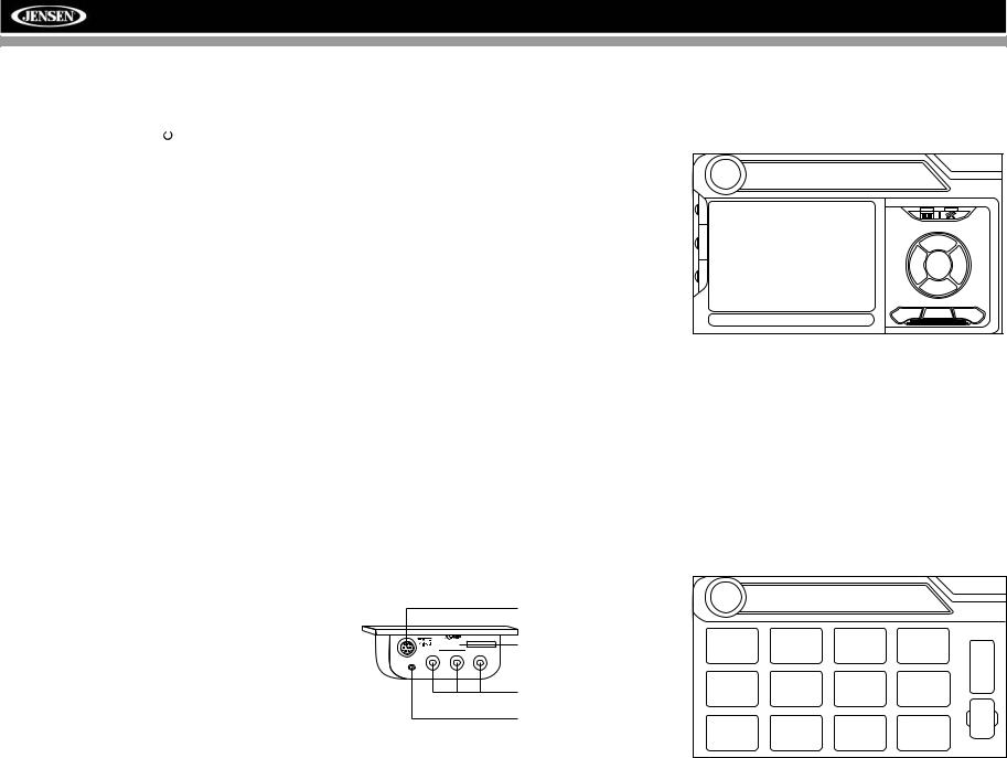
USING THE TFT MONITOR
Open/Close TFT Monitor
Open TFT Monitor
Press the OPEN button (1) on the front panel or press the ( ) button (25) on the remote control to slide the monitor panel down to reveal the disc and SD card slots.
Close TFT Monitor
Press the OPEN button (1) on the front panel or press the ( ) button (25) on the remote control close the monitor panel.
Monitor Tilt Angle Adjustment
A known characteristic of LCD panels is the quality of the display in relationship to the viewing angle. The monitor angle can be adjusted for optimum viewing using one of the following methods.
Step by Step Angle Adjustment
Press the ( ) or (
 ) button on the remote control (26, 27) to adjust the tilt angle of the screen one step at a time.
Continuous Angle Adjustment
Press and hold the ( ) or (
 ) button on the control panel or remote control to adjust the tilt angle in a continuous motion.
Reverse Driving Use
If the rear-view video camera is connected, the unit is on, and the monitor is stationed inside the main compartment of the unit, the monitor automatically moves into the viewing position and switches to CAMERA mode upon reverse driving. When the reverse driving stops, the monitor returns to the main storage compartment.
If the monitor is in display mode, the monitor automatically switches to CAMERA mode upon reverse driving. When the reverse driving stops, the monitor returns to its original input mode.
Aspect Ratio
Press the WIDE button (28) on the remote control or WIDE/ PIC button (7) on the monitor to adjust the aspect ratio as follows (only active with video source):
CINEMA
The entire screen is extended horizontally to the aspect ratio of 16 to 9. The extension ratio is the same at any point.
NORMAL
The conventional display image has a 4 to 3 ratio of horizontal to vertical, leaving a blank area on the right and left sides of the display.
STANDBY
Screen becomes black. Touch screen to resume.
Image Setting
Table 2 shows the video output mode for each playing source.
Table 2: Video Output Modes
Playing Source |
Video Output Modes |
|
|
|
|
RADIO |
RGB Mode |
|
|
SAT |
RGB Mode |
|
|
DISC |
RGB Mode |
|
|
BT |
RGB Mode |
|
|
AUX 1 |
CVBS Mode |
|
|
AUX 2 |
CVBS Mode |
|
|
NAV |
RGB Mode |
|
|
CAMERA |
CVBS Mode |
|
|
*CVBS – Composite Video Baseband Signal
Parameter Adjustment Procedure
1.Enter Picture Quality Setting Mode:
Press the PIC button (24) on the remote control or press and hold the WIDE/PIC button (7) on the monitor.
2.Select Item to Set:
Use the up/down joystick buttons to select “BRIGHT” or “CONTRAST”.
3.Set Parameters:
Use the left/right joystick buttons to modify the settings.
4.Exit Picture Quality Setting Mode:
Press the PIC button on the remote control or the WIDE/ PIC button on the monitor
Parking Brake Inhibit
When the pink "Parking" wire is connected to the vehicle Parking Brake circuit, the front TFT monitor will display video when the Parking Brake is engaged. (When the pink wire is grounded via the Parking Brake circuit, video will be displayed.)
13
VM9022HDN
OPERATING INSTRUCTIONS
Power On / Off
Press the /SRC button (6) (or any other button on the front
of the unit except reset), or the /POWER button (4) on the remote control, to turn the unit on. The buttons on the front of the unit light up and the current mode status appears on the TFT screen (17).
Press and hold the button to power off the unit.The monitor is drawn back into the main compartment.
Audible Beep Confirmation
An audible beep tone confirms each function selection. The Beep tone can be disabled through the Setup menu.
Volume Adjustment
To increase or decrease the volume level, turn the rotary encoder (5) on the front panel or press the VOL+/ VOL- buttons (15, 16) on the remote control. When the volume level reaches “0” or “40”, a beep sounds, indicating that the adjustment limit has been reached. The volume ranges from “0” to “40”. The TFT screen displays the volume level for 3 seconds.
Programmable Turn-On Volume
This feature allows the user to select a turn-on volume setting regardless of the volume setting prior to turning the unit off. To program a specific turn-on volume level, turn the AUDIO control (2) to adjust the volume to the desired turn-on volume. Push and hold the AUDIO button while the yellow speaker icon and level indication is displayed on the screen. The unit will beep two times to confirm your turn-on volume setting.
Mute
Press the MUTE button on the front panel (8) or remote control (3) to mute the volume from the unit. Press the MUTE button again to restore the volume. “MUTE” is displayed on the screen. Adjusting the volume or using any of the audio setup features cancels the mute function.
Line Mute
If the “MUTE” wire is connected, audio output mutes when a telephone call is received by a cell phone.
Steering Wheel Control (SWC)
The VM9022HDN is compatible with the PAC (Pacific Accessory Corporation) steering wheel control adapter SWIPS. A 3.5mm female connector (labeled “SWC Interface”) on the back of the head unit allows connectivity to the PAC
adapter. Please refer to the instructions included with the PAC adapter for detailed installation information.
SWC Functions
The following controls are available for most vehicles:
1.Vol Up
2.Vol Down
3.Mute
4.Seek Up / Next Track / ** Preset Up
5.Seek Down / Previous Track / ** Preset Down
6.SRC (Source)
7.** Select
8.** Select
9.Band
** If additional steering wheel control buttons are available on the vehicle, function 7 / 8 may be assigned the "Select" feature. This feature / function may not be available on some vehicles.
Select Operation
If "Select" (function 7 or 8) is held down and function 4 is pressed momentarily, Preset Up will be selected. If "Select" (function 7 or 8) is held down and function 5 is pressed momentarily, Preset Down will be selected.
Playing Source Selection
Press the SRC button on the front panel (6) or remote control
(8) to change between available playing sources in the following order: RADIO, SAT, DISC, NAV, BT, iPod, SD, USB, AUX1, AUX2 and CAMERA. The playing mode is displayed on the TFT screen.
Auxiliary Devices
External peripheral devices can be connected to this unit via RCA output (AUX IN 2) or the MediaLink4.
iPod Connector
(GEN 5 Recommended)


 MediaLink USB Connector (Type A)
3.5mm - Audio VIDEO |
LEFT |
RIGHT |
RCA Inputs (AUX 1)
3.5mm Left & Right
Stereo Inputs (AUX 1)
Select “AUX1” to play an auxiliary device connected via the MediaLink RCA or 3.5mm inputs. For example, you can play
music files from a portable music player, video from a video camera and even view photos stored on a digital camera.
Select “AUX2” mode to access and control auxiliary devices
01:53 PM
AUX1 No Video Signal
E
Q
R
E
A
R
P
I
P
Stereo |
PLII Music |
connected to the “AUX IN 2” inputs on the back of the radio.
Selecting a Source while Navigating
While navigating, other sources may be selected and listened to such as AM-FM Tuner, CD, etc. To select a source, press
the /SRC button (6) and then select a source from the Front Source Menu. Navigation voice prompts will be heard automatically, although the navigation map cannot be seen. (The selected source audio will be muted until the navigation voice prompt command is completed, after which the source audio will resume.)
Source Menu
To access the SOURCE MENU, touch the TFT screen in the top left corner of the screen.
DISC |
SOURCE MENU |
|
|
|
|
|
|
|
F |
DISC |
SD |
USB |
NAV |
R |
|
|
|
|
O |
|
|
|
|
N |
|
|
|
|
T |
RADIO |
SAT |
iPod |
BT |
R |
|
|
|
|
E |
|
|
|
OFF |
A |
AUX 1 |
AUX 2 |
CAMERA |
R |
|
|
|
|||
14
VM9022HDN
This menu allows you to select a source for the front or rear zone. Touch FRONT or REAR to choose the zone for which you would like to specify the source. (See “Multi-ZONE Operation” on page 16.)
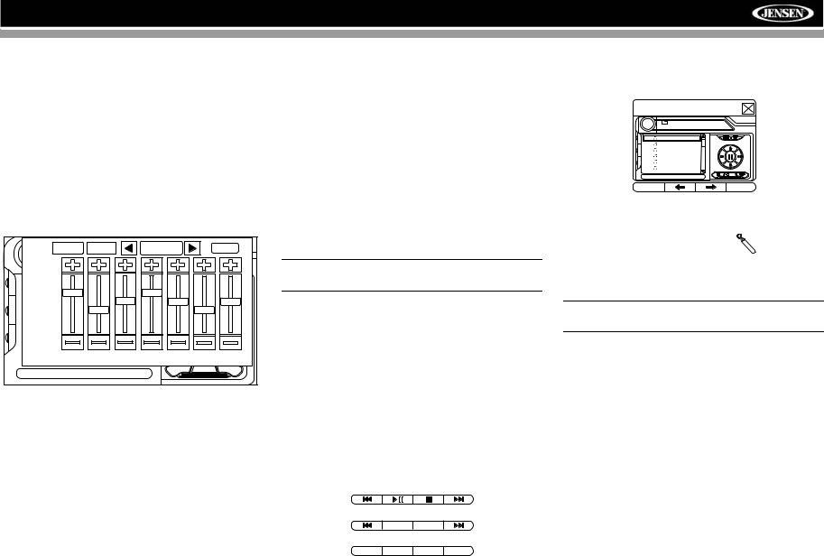
Audio Control Menu
The Audio Control menu features a 7-band graphic equalizer, which allows you to easily adjust your audio system to meet the acoustical characteristics of your vehicle, which vary depending on the type of vehicle and its measurements. Proper setting of the Fader and Balance boosts the effects of the cabin equalizer.
Press the AUDIO button (5) on the front panel to display the audio menu.
|
FAD-BAL |
EQ |
|
USER |
|
|
BACK |
|
|
+12 — |
|
|
|
|
|
|
|
E |
|
|
|
|
|
|
|
|
Q |
|
|
|
|
|
|
|
|
R |
0 — |
|
|
|
|
|
|
|
|
|
|
|
|
|
|
|
|
E |
|
|
|
|
|
|
|
|
A |
|
|
|
|
|
|
|
|
R |
|
|
|
|
|
|
|
|
P |
–12 — |
|
|
|
|
|
|
|
|
|
|
|
|
|
|
|
|
I |
|
|
|
|
|
|
|
|
P |
|
|
|
|
|
|
|
|
|
|
80 |
250 |
600 |
1k |
4k |
10k |
16k |
|
EQ: |
User |
|
|
|
|
|
|
To adjust an audio feature:
1.Use the left/right joystick buttons to highlight the audio feature to be adjusted.
2.Press the joystick Enter button on the control panel (13) or remote control (18) to select the highlighted option.
3.Use the joystick to adjust the selected feature to the desired setting.
Table 3: Audio Adjustments
Function |
|
Adjustment Options |
|
|
|
|
|
|
EQ |
User |
In user mode, you can manually adjust |
|
|
each of the seven frequency bands. |
|
Acoustic |
Use the on-screen arrows to select a |
|
|
predefined equalization curve. |
|
Urban |
|
|
|
|
|
Rave |
|
|
|
|
|
Latin |
|
|
|
|
|
Dance |
|
|
Hip Hop |
|
|
|
|
|
Rock |
|
|
|
|
FAD-BAL |
Use this screen to adjust the output level for each |
|
|
speaker in your surround system from 0 to -24dB. |
|
|
You can also adjust the master volume from this |
|
|
screen. |
|
NOTE: The EQ mode will automatically change to “USER” when individual EQ bands are adjusted.
Proper setting of the Fader and Balance complement the effects of the cabin equalizer.
The Audio menu will automatically exit after a few seconds of inactivity. To exit quickly, touch the top left corner of the screen or press and hold the AUDIO button (5).
Alternate Display Options
A menu located on the left side of the screen provides immediate access to the Equalizer, Rear Zone screen view and PIP (Picture in Picture) features.
•EQ: Touch to view Spectrum Analyzer > Equalizer.
•REAR: Touch to view the Rear Zone screen. Control options appear below the PIP image, depending on the source.
DISC
AM/FM RADIO
BAND AS
SATELLITE
CAT– CH– CH+ CAT+
•PIP: Touch to view the Rear Zone, current Front Zone, or NAV screen. Use the left/right arrows below the PIP image to change the PIP source.
PIP: DISC
|
DISC |
(Root) |
01:02 AM |
|
MP3 4/84 |
00:00:23 |
|
|
|
||
Q |
1 |
Cherry Poppin Da |
|
E |
|
|
|
R |
2 |
Chris Isaak - Baby |
|
|
|
|
|
E |
3 |
Crazy Town - Butt |
|
A |
|||
R |
4 |
Phish - Birds Of A |
|
|
|||
P |
5 |
Phish - Bouncin' R |
|
I |
|||
P |
|
|
|
|
6 |
Phish - Freebird (L |
|
|
|
|
1/2 |
System Reset
To correct a system halt or other illegal operation, use the tip of a pen
to press the reset button (12) located
on the front bottom-right corner of the unit. After a system reset, the unit restores all factory default settings.
NOTE: If the unit is reset while a DVD is playing, the DVD resumes play once the reset is complete.
15
VM9022HDN
MULTI-ZONE OPERATION
Independent sources can be played simultaneously on the VM9022HDN. For example, a video game console can be seen on the front screen while DVD video is available to rear passengers.
DVD and SD Card sources cannot be selected for simultaneous Front / Rear operation. For example, if DVD is selected as the Rear Zone source, then SD Card cannot be selected as a Front Zone source. In addition, HD Radio and SAT cannot be selected for simultaneous Front / Rear operation.
Table 4: Multi-Zone Source Options
FRONT |
|
|
|
|
|
REAR ZONE |
|
|
|
|
||
ZONE |
|
|
|
|
|
|
|
|
|
|
|
|
HD |
Disc |
SD |
USB |
NAV |
|
SAT |
iPod |
BT |
Aux 1 |
Aux 2 |
Cam |
|
|
Radio |
|
|
|
|
|
|
|
|
|
|
|
HD |
O |
O |
O |
O |
O |
|
X |
O |
X |
O |
O |
O |
Radio |
|
|
|
|
|
|
|
|
|
|
|
|
Disc |
O |
O |
X |
O |
O |
|
O |
O |
X |
O |
O |
O |
SD |
O |
X |
O |
O |
O |
|
O |
O |
X |
O |
O |
O |
USB |
O |
O |
O |
O |
O |
|
O |
O |
X |
O |
O |
O |
NAV |
O |
O |
O |
O |
O |
|
O |
O |
X |
O |
O |
O |
SAT |
X |
O |
O |
O |
O |
|
O |
O |
X |
O |
O |
O |
iPod |
O |
O |
O |
O |
O |
|
O |
O |
X |
O |
O |
O |
BT |
O |
O |
O |
O |
O |
|
O |
O |
O |
O |
O |
O |
Aux 1 |
O |
O |
O |
O |
O |
|
O |
O |
X |
O |
O |
O |
Aux 2 |
O |
O |
O |
O |
O |
|
O |
O |
X |
O |
O |
O |
Cam |
O |
O |
O |
O |
O |
|
O |
O |
O |
O |
O |
O |
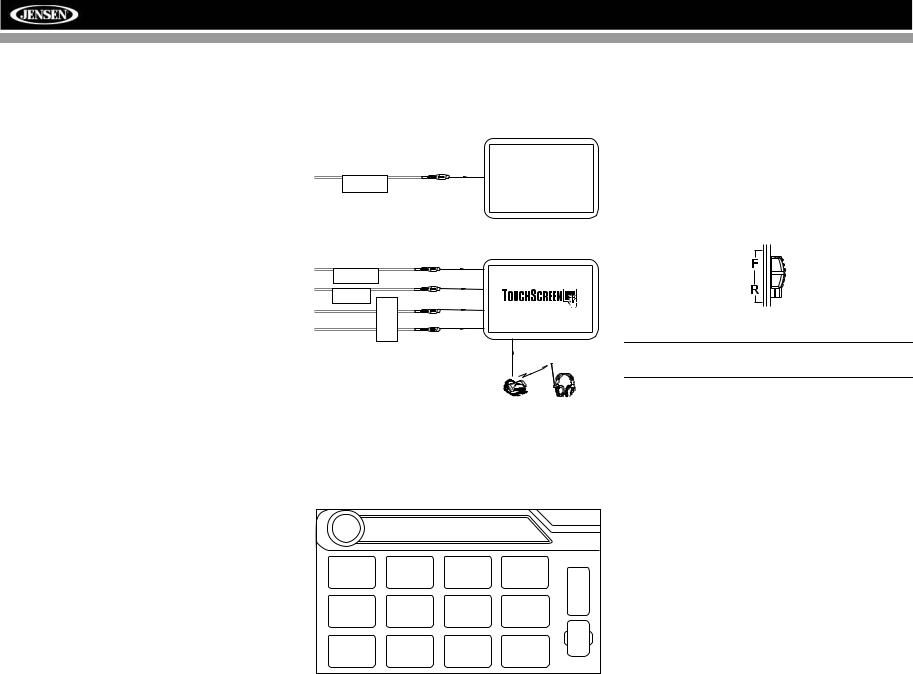
Connecting the Rear Zone Touch Screen
You can connect up to two additional monitors (sold separately) for rear passengers, one of which can be a Touch Screen.
You can also connect a wireless headphone system to one of your rear monitors, as illustrated below.
Rear Video Screen
(Sold Separately)
YELLOW
VIDEO OUT 1
MZ7-TFT Touch Screen
(Sold Separately)
YELLOW
VIDEO OUT 2 |
|
|
BLACK |
MZ7-TFT |
|
HEADPHONE MULTIZONE |
WHITE |
|
RED |
Wireless Headphone
(OPTIONAL)
Changing the Rear Zone Source
To access the SOURCE MENU, touch the TFT screen in the top left corner of the screen.
DISC |
SOURCE MENU |
|
|
|
|
|
|
|
F |
DISC |
SD |
USB |
NAV |
R |
|
|
|
|
O |
|
|
|
|
N |
|
|
|
|
T |
RADIO |
SAT |
iPod |
BT |
R |
|
|
|
|
|
|
|
|
|
E |
|
|
|
OFF |
A |
|
|
|
R |
|
AUX 1 |
AUX 2 |
CAMERA |
|
|
This menu allows you to select a source for the front or rear zone. Touch FRONT or REAR to choose the zone for which you would like to specify the source.
Controlling the Rear Zone Screen(s)
If you have a rear touch screen installed, you can touch the screen to control most rear zone functions.
You can also use the remote control. The VM9022HDN remote controls both the front and rear zones. To switch from front to rear zone, move the F/R switch (32) located on the right side of the remote controller.
NOTE: You cannot change or control the front zone source from the rear zone video screen.
Touch the REAR button on the left side of the screen to view a “Picture in Picture” image of the rear screen.
Turning the Rear Screen Off
Touch the OFF button (on the SOURCE MENU) to suspend operation of the rear screen. Any operation assigned exclusively to the rear source will be suspended until reactivated using either the front or rear zone touch screen or the remote control.
16
 Loading...