


NX-590NE

NX-590NE Internet Interface
Installation Manual
P/N 466-2330 • REV C • October 2012

Copyright
© 2012 UTC Fire & Security Americas Corporation, Inc.
Interlogix is part of UTC Climate Controls & Security, a unit of United Technologies
Corporation. All rights reserved.
This document may not be copied in whole or in part or otherwise reproduced without
prior written consent from UTC Fire & Security except where specifically permitted
under US and international copyright law.
Document number 466-2330 REV C. October 2012
Disclaimer
The information in this document is subject to change without notice. UTC Fire &
Security assumes no responsibility for inaccuracies or omissions and specifically
disclaims any liabilities, losses, or risks, personal or otherwise, incurred as a
consequence, directly or indirectly, of the use or application of any of the contents of
this document. For the latest documentation, contact your local supplier or visit us
online at www.utcfireandsecurity.com.
This publication may contain examples of screen captures and reports used in daily
operations. Examples may include fictitious names of individuals and companies. Any
similarity to names and addresses of actual businesses or persons is entirely
coincidental.
Trademarks and
patents
Other trade names used in this document may be trademarks or registered
trademarks of the manufacturers or vendors of the respective products.
Intended use
Use this product only for the purpose it was designed for; refer to the data sheet and
user documentation. For the latest product information, contact your local supplier or
visit us online at www.utcfireandsecurity.com.
FCC compliance
This equipment has been tested and found to comply with the limits for a Class B
digital device, pursuant to part 15 of the FCC rules. These limits are designed to
provide reasonable protection against harmful interference when the equipment is
operated in a residential environment. This equipment generates, uses, and can
radiate radio frequency energy and, if not installed and used in accordance with the
instruction manual, may cause harmful interference to radio communications.
Changes or modifications not expressly approved by the party responsible for
compliance could void the user’s authority to operate the equipment.
EMC directive
The European Union directive on electromagnetic compatibility (2004/108/EC)
requires non-European manufacturers to designate an authorized representative in
the Community.
Our European representative is UTC Fire & Security, Kelvinstraat 7, 6003 DH Weert,
Nederland.
Regulatory
Contact information
For contact information, see www.utcfireandsecurity.com. or www.interlogix.com
Technical support
Toll-free: 888.437.3287 in the US including Alaska, Hawaii, Puerto Rico, and
Canada. Outside the tool-free area, contact your dealer.

Content
Preface ...................................................................................................... 3
Conventions used in this document ...................................................... 3
Safety terms and symbols....................................................................... 3
Product overview ................................................................................... 5
Installation................................................................................................ 5
Mounting .................................................................................................... 5
Wiring ......................................................................................................... 6
Enrolling devices ...................................................................................... 9
Reset .......................................................................................................... 9
Programming......................................................................................... 10
Using an LED keypad ............................................................................ 10
Programming data.................................................................................. 11
Using an LCD keypad............................................................................ 12
Programming locations ...................................................................... 14
Location 0 – Operation mode ............................................................... 14
Location 1 – Partitions reporting via TCP/IP to receiver 1 ............... 15
Location 2 – Partitions reporting via TCP/IP to receiver 2 ............... 16
Location 3 – Partitions reporting via e-mail to account 1 ................. 16
Location 4 – Partitions reporting via e-mail to account 2 ................. 16
Locations 5 to 7 - SMTP e-mail authentication.................................. 16
Locations 8 to 12 - Reserved ............................................................... 17
Locations 13 to 16 - Return e-mail name ........................................... 17
Locations 17 to 24 - TCP/IP receiver name ....................................... 17
Locations 25 to 28 - Reserved ............................................................. 17
Locations 29 to 36 - E-mail account name ......................................... 17
Locations 37 to 40 - E-mail server name............................................ 18
Locations 41 to 44 - Download computer name................................ 18
Locations 45 to 53 - IP addresses ....................................................... 19
Location 54 - Subnet mask ................................................................... 19
Location 55 - Receiver alarm port ....................................................... 19
Location 56 - Download software port ................................................ 20
Location 57 - SMTP e-mail port ........................................................... 20
Locations 58 and 59 - Reserved .......................................................... 20
Location 60 - SIA or Contact ID account number ............................. 20
Location 61 - Phone line receiver number ......................................... 20
Location 62 - Line number .................................................................... 20
NX-590NE Internet Interface Installation Manual i

Location 63 - Timers and counters ...................................................... 20
Locations 64 to 71 - Partition account number .................................. 21
Locations 72 to 82 - Reserved ............................................................. 21
Locations 83 to 86 - Premise server name (Europe only) ............... 21
Location 87 - Automation (premise server) IP address.................... 21
Location 88 - Automation system port ................................................ 22
Location 89 - Automation event transitions ........................................ 22
Location 90 - Automation requests/commands ................................. 22
Location 91 - Keypad address for automation text retrieval ............ 23
Locations 92 to 125 - Reserved ........................................................... 24
Locations 126 to 133 ............................................................................. 24
Program worksheets ........................................................................... 25
Programming tasks ............................................................................. 32
Set up an IP address for the NX-590NE............................................. 32
Set up a dynamic IP to the NX-590NE ............................................... 32
Send events as e-mail messages only ............................................... 32
Send events to receiver 1 only ............................................................. 33
Send events to receiver 2 only ............................................................. 33
Set up DNS ............................................................................................. 34
View version of NX-590NE and PIC.................................................... 34
View DHCP assigned IP address ........................................................ 34
DL900 utility............................................................................................. 34
Specifications ....................................................................................... 35
Contacting us ........................................................................................ 36
Online resources .................................................................................... 36
ii NX-590NE Internet Interface Installation Manual

Bold
Menu items and button.
Italic
Emphasis of an instruction or point; special terms.
File names, path names, windows, panes, tabs, fields, variables, and other GUI
elements.
Titles of books and various documents.
Blue
(Electronic version.) Hyperlinks to cross-references, related topics, and URL
addresses.
Monospac
e
Text that displays on the computer screen.
Programming or coding sequences.
Preface
This is the NX-590NE Internet Interface Installation Manual. This document
includes an overview of the product and detailed instructions explaining:
• how to install the module; and
• how to program the module.
There is also information describing how to contact technical support if you have
questions or concerns.
To use this document effectively, you should have the following minimum
qualifications:
• a basic knowledge of NetworX systems;
• a basic knowledge of electrical wiring and low-voltage electrical connections;
and
• a basic knowledge of computer system networking.
Read these instructions and all other documentation entirely before installing or
operating this product. The most current versions of this and related
documentation may be found on our website. Refer to
http://www.utcfireandsecuirty.comfor instructions on accessing our online
publication library.
Note: A qualified service person, complying with all applicable codes, should
perform all required hardware installation.
Conventions used in this document
The following conventions are used in this document:
Safety terms and symbols
These terms may appear in this manual:
NX-590NE Internet Interface Installation Manual 3

Caution: Cautions identify conditions or practices that may result in damage to
the equipment or other property.
WARNING: Warning identify conditions or practices that could result in
equipment damage or serious personal injury.
4 NX-590NE Internet Interface Installation Manual

Product overview
The NX-590NE is a dual microprocessor-controlled Internet/Intranet (TCP/IP)
interface used to connect the control panel to the OH Network Receiver. This
interface allows any or all events from the panel to be reported over the network.
The NX-590NE has a fixed address of 79.
Installation
To install the interface module, you will need to mount and wire the board, and
enroll the module in the panel.
Mounting
We recommend that you mount the NX-590NE with UCSIMM PCB in the
mounting position located closest to the NX panel PCB as shown in Figure 1 on
page 6.. If another board is already mounted in the location closest to the NX
panel PCB, mount the NX-590NE in the next available location.
To mount the board, do the following:
1. Place the first black plastic PCB guide in the top insertion point, grooved edge
downward. The half-moon protrusion will be in the large hole. It does not
require force.
2. Insert one of the provided screws into the smaller hole (from the inside of the
enclosure) to secure it in place. Position a screwdriver through the notch that
runs the length of the guide, to tighten the screw.
3. Position the second PCB guide opposite the first (grooved edge up) and place
it in the lower insertion point, using the same procedure. Once you mount the
guide, screw it in securely.
4. Slide the board into both guides.
NX-590NE Internet Interface Installation Manual 5
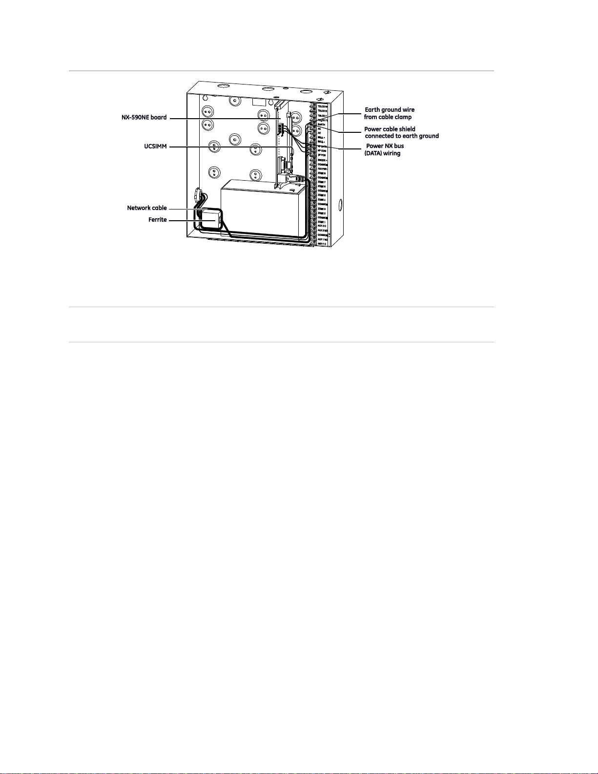
Figure 1: Mounting the board
Wiring
Caution: Do not apply power to any component until the installation is complete.
Damage to components may occur if power is incorrectly applied.
CE and FCC Part B compliance
As of January 1, 1996, all new European Union member installations must be CE
compliant.
In addition, we recommend that you use the following wiring methods:
• Use 2-conductor, shielded security and alarm cable for the power cable.
• Connect the power cable shield to the earth terminal on the NX panel PCB
(see Figure 1 above).
Note: The other end of the power cable shield should be cut off and not
connected.
• Earth ground the NX panel. Connect the earth ground wire to the earth
terminal on the NX panel PCB and connect the other end at the cable’s
entrance to the panel or cable clamp. In addition, connect the nearest earth
ground to the panel or to the cable clamp as shown in Figure 2 on page 7.
6 NX-590NE Internet Interface Installation Manual

Figure 2: Earth ground terminals
Ferrite installation
• Prior to connecting the network cable to the NX-590NE PCB, install the ferrite
provided onto the network cable. Loop the cable two times through the ferrite.
We recommend that you locate the ferrite inside the NX panel at the entrance
to the network cable (see Figure 1 on page 6). An alternative location is
directly outside the enclosure at the entrance of the network cable.
Note: When routing wire inside the NX panel, do not place wiring on, or near,
the NX-590NE UCSIMM PCB.
Figure 3 below shows the NX-590NE board.
Figure 3: NX-590E board
To wire the board, see Figure 3 above and do the following:
1. Use the J16 10/100 ethernet jack to connect to the ethernet cable.
NX-590NE Internet Interface Installation Manual 7
J3 pins
J19 pins
Pin 1 - NX bus (Data)
Pin 1 - +12VDC
Pin 2 - Ground
Pin 2 - No connection
Pin 3 - +12 VDC
Pin 3 - Ground
Pin 4 - NX bus (Data)
Length in feet
250
500
1000
2000
Connected to NX panel
22
20
16
14
Connected to NX-320E
22
18
16
12
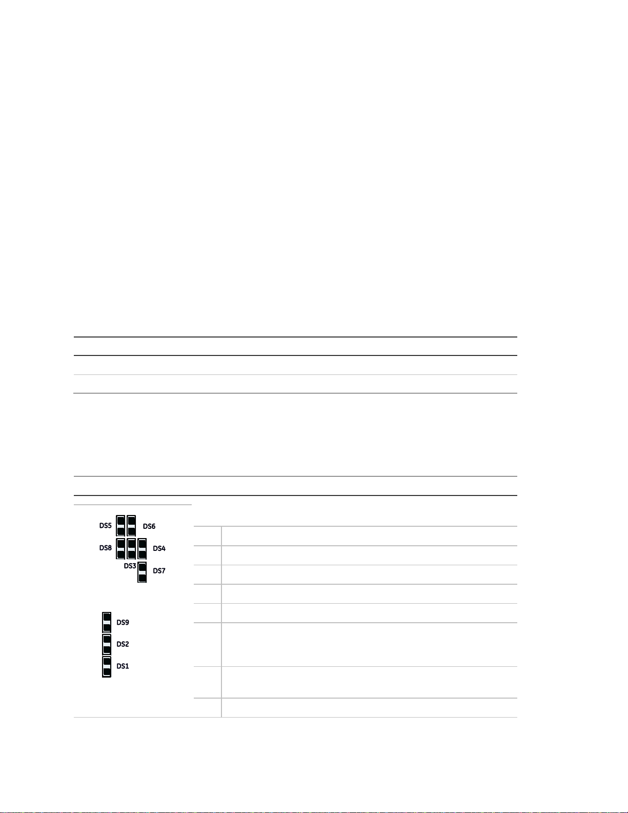
LED Description
DS1
Flashes each time the NX-590NE has an opportunity to access
the NetworX bus. It should flash about two times per second.
DS2
Flashes when communicating with NX bus (Data).
DS3
Flashes when waiting for UCSIMM acknowledgment.
DS4
Flashes when waiting for NX bus (Data) reply.
DS5
Flashes when message received from NX bus (Data).
DS6
Flashes when message sent to NX bus (Data).
DS7
On when U-Boot is running. Flashes when U-Boot is stopped,
either an error has occurred or stopped via console. Off during
application.
DS8
On when uClinux Kernel coming up, then shows an application
heartbeat.
DS9
On when power is on.
2. Connect the J3 screw terminals or the J19 plug terminal to the control panel
keypad databus.
Note: The J6 console (DB-9 female) is used by the factory to troubleshoot and
test the board. The J9 PIC upgrade connector is used for future upgrades to the
PIC processor.
Table 1 below shows the minimum wire gauge and maximum wire length allowed
for the NX-590NE.
Table 1: Minimum wire gauge by length
LEDs
Table 2 below describes the LEDs on the NX-590NE board
Table 2: NX-590NE LED indicators
Table 3 on page 9 describes the LEDs on the UCSIMM module
8 NX-590NE Internet Interface Installation Manual

LED
Description
DS1/5
(green)
On = Link actively present; Off = No link actively present; Flashing = Network
activity detected
DS2/6
(yellow)
On = 100 Mbps; Off = 10 Mbps
DS3/7 (red)
On = Full duplex; Off = Half duplex
DS4/8 (red)
On = Collision
Table 3: UCSIMM LED indicators
Enrolling devices
The NetworX control panels can locate, store, and supervise keypads, zone
expanders, wireless receivers, output modules, and any other device on the
keypad bus. To enroll the devices, enter program mode (see “Programming” on
page 10). When you exit program mode, the control panel will enroll the devices.
During the enrollment, which takes about 12 seconds, the Service LED will
illuminate and the system will not accept user codes. Once you enroll a module,
if it is not detected, the Service LED will illuminate.
Reset
Briefly shorting the JP4 hardware reset connector pins (Figure 3 on page 7) will
force an NX-590NE complete hardware reset.
NX-590NE Internet Interface Installation Manual 9

Programming
You can use an LED keypad or LCD keypad to program the module.
Using an LED keypad
To program the module with an LED keypad, do the following:
1. Enter *, 8. All of the function key LEDs will begin to flash.
2. Enter the Go To Program code (default is 9713). If the code is valid, the
Service LED will flash, and the function LEDs will illuminate steadily,
indicating you should enter the device to program.
3. Enter 7, 9, #, the address of the NX-590NE. The Armed LED will illuminate
until you enter a programming location.
4. Enter the programming location followed by the # key. The Armed LED will
begin to flash. If this is a valid location, the Armed LED will extinguish, the
Ready LED will illuminate, and the binary data for the first segment of this
location will appear on the Zone LED.
5. To change the data, enter the data followed by the * key. The location will
automatically increment to the next segment. The data for that segment will
display. Repeat the procedure until the system reaches the last segment.
6. To exit this location without changing the data, press the # key.
7. To review the data, press the * key but do not enter data. Each time you
press *, the next segment displays. After you program the last segment for a
location, press * to exit that location. The system will turn the Ready LED off
and the Armed LED on. As before, you are now ready to enter another
programming location.
Note: If you attempt to program an invalid entry for a particular segment, the
keypad sounder will emit a triple-beep and remain in that segment until there
is a valid entry.
8. To enter another location, do one of the following:
• Enter the location number followed by the # key.
• Press Police for the next location.
• Press Fire for the previous location.
• Press Auxiliary for the same location.
9. Press Exit to exit this module. Press Exit again, to completely exit program
mode.
10 NX-590NE Internet Interface Installation Manual
 Loading...