


 Loading...
U.S.
T 855 536 3573
F 561 998 6224
Asia
T 65 6424 7932
F 65 6424 7978
Australia
T 61 3 9239 1200
F 61 3 9239 1299
Canada
T 800 267 6317
F 613 737 5517
EMEA
T 48 58 326 22 40
F 48 58 326 22 41
Latin America
T 503 589 8614
F 561 994 6572
www.utcfireandsecurity.com
© 2012 UTC Fire & Security. All rights reserved.
UTC Fire & Security, 9 Farm Springs Road, Farmington, CT 06034-4065, USA
Transition Series
Multi-Technology Access Readers
Description
Transition™ multi-technology card readers feature simultaneous compatibility with multi-vendor 125 kHz Proximity, Mifare (ISO 14443A), and Vicinity (ISO 15693) credential technologies—all in one reader. With this remarkable technology combination, security administrators can now deploy the Transition readers into new or existing facilities.
Figure 1. Multi-technology Readers
Figure 2. Direct wall mounting
2b. Models 520/525 can be mounted using a second pair of vertical mounting holes, horizontally spaced 2.75” (70 cm) from the first pair.
Figure 3. T520/525 Direct wall mounting alternative
Mounting the Reader
All models of the multi-technology series readers can be mounted using a U.S. single-gang electrical box or directly to a wall.
1.Find a suitable mounting position on the door frame or wall.
Note: For out of doors or wet locations, it is recommended that the gasket provided be installed on the base as shown in Figure 5.
2.If mounting directly to the wall, use one of the following methods:
2a. Drill two vertical mounting holes from 3.25”
(83 cm) to 4.891” (125 cm) apart on the mounting surface of the door frame or wall.
3.Drill one 0.625” (15.87 mm) diameter hole in wall for the pigtail wire connection.
4.Follow the Cable Connection Chart to connect the reader to the field panel and external door equipment.
5.Mount the base plate to the wall using the supplied screws.
6.Install gasket if required, see Figure 5.
7.Install the top cover to the reader base. The base plate and top cover guides should be aligned, so the connectors seat correctly.
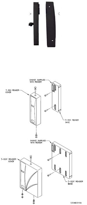
Figure 4. Aligning base plate and top cover
Base plate |
|
|
|
|
|
|
|
|
|
|
|
|
|
|
|
|
|
|
|
|
|
|
|
|
|
|
|
|
|
Top cover |
|
|
|
|
|
|
|
|
|
|
|
|
|
|
|
|
|
|
|
|
|
|
|
||||||||
|
|
|
|
|
|
|
|
|
|
|
|
|
|
|
|
|
|
|
|
|
|
|
||||||||
|
|
|
|
|
|
|
|
|
|
|
|
|
|
|
|
|
|
|
|
|
|
|
|
|
|
|
|
|
|
|
8.Verify the connection is secure and install the security screws on the top and bottom of the reader.
9.Cover the exposed screws with the rubber
plugs provided.
Figure 5. Gasket detail
Connecting the Cable
1.The readers are supplied with a 12-conductor cable pigtail with drain wire. Connect the pigtail to the host panel. Use the Cable Connection
Chart (below) to correctly match the color of each wire.
Color |
Signal |
|
|
Red |
6 to 16 VDC |
|
|
Black |
Ground |
|
|
Green |
Data 0 |
|
|
White |
Data 1 |
|
|
Orange |
Green LED Control |
|
|
Brown |
Red LED Control |
|
|
Yellow |
Beeper Control |
|
|
Gray |
Door DI |
|
|
Pink |
REX DI |
|
|
Tan |
Tamper Output |
|
|
Blue |
Hold |
|
|
Purple |
Reserved |
|
|
........ |
Drain Wire |
|
|
2.Use a DC Power source between 6-16 VDC.
3.Verify the reader is properly grounded by attaching the ground wire to an earth ground connection at the power supply or field panel end of the cable. Connect reader’s drain wire to the cable shield. Connect shield wires at the field panel. The recommended cable gauge is 18-gauge to 22-gauge. Check with the cable supplier to determine the best choice for the application and installation distance.
Testing the Reader
1.Power up the reader. Verify the power-on self test
LED/beep sequence:
-green LED flashes; two short beeps
-yellow LED flashes; three short beeps
-red LED flashes.
-yellow LED flashes.
2.Verify the yellow LED is on continously indicating the reader is ready.
3.Present a badge that has been properly enrolled in the system. Verify the yellow LED flashes and a short beep is heard.
Removing the Cover
1.Remove all security screws.
2.Pull cover off the base. Refer to Figure 4 on page 2.
Loading...