


 Loading...
Indoor/Outdoor PIR Motion Sensors
Installation Instructions
Introduction
This is the GE Indoor/Outdoor PIR Motion Sensors Installation Instructions for model numbers:
•60-639-95R (indoor)
•60-639-95R-OD (outdoor)
•60-639-43-EUR (indoor, not investigated for use by UL)
•60-639-43-ERT-OD (outdoor, not investigated for use by UL)
Passive-infrared (PIR) motion sensors detect movement within a specific area by sensing the infrared energy emitted from a body as it moves across the sensor’s field of view, causing a temperature change in the sensor’s zones. When the sensor detects this motion, it transmits an alarm signal to the control panel.
Use the indoor sensors to protect large areas and open floor plans or as backup protection for door/window sensors.
Use the outdoor sensors to identify motion in a protected outdoor area. Detected motion in this protected area can sound chimes or turn on outside lights. Do not use the outdoor sensors for intrusion protection.
Features include:
•35 by 40 ft. (10.7 x 12.2 m) coverage area for standard and optional pet alley lenses;
•masking kit to block portions of the coverage area;
•three-minute transmitter lockout time after an alarm to extend battery life;
•cover-activated tamper (an optional wall-activated tamper is provided);
•supervisory signal transmitted every 64 minutes to the control panel;
•sensor low battery reports (trouble) to the control panel; and
•field-selectable sensitivity options.
Indoor sensor installation
Use the following installation guidelines:
•If possible, mount the sensor within 100 ft. (30.5 m) of the panel. While the transmitter may have a range of 500 ft. (152.4 m) or more out in the open, the environment at the installation site can have a significant effect on transmitter range.
•Position the sensor to protect an area where an intruder is most likely to walk across the detection pattern. (Figure 1).
Figure 1. Overhead detection pattern
466-1534G • August 2006
Copyright © 2006, GE Security Inc.
•Mount the sensor between 5 and 8 ft. (1.5 and 2.4 m) from the floor (Figure 2). We recommend a height of 7.5 ft. (2.3 m). Higher mounting provides better range, and lower mounting provides better protection close to the sensor. See
Pet alley lens on page 3.
Figure 2. Detection pattern
Top view
20 ft.
6 m
10 ft.
3 m
0 ft.
0 m
10 ft.
3 m
20 ft.
6 m
5 ft. |
15 ft. |
25 ft. |
35 ft. |
1.5 m |
4.5 m |
7.5 m |
10.5 m |
Side view with mounting height of 7.5 ft. (2.3 m)
8 ft. (2.4 m) |
|
|
|
|
4 ft. (1.2 m) |
|
|
|
|
0 ft. (0 m) |
5 ft. |
15 ft. |
25 ft. |
35 ft. |
|
||||
|
1.5 m |
4.5 m |
7.5 m |
10.5 m |
Side view with mounting height of 5 ft. (1.5 m) 8 ft. (2.4 m)
4 ft. (1.2 m) |
|
|
|
0 ft. (0 m) |
|
|
|
5 ft. |
15 ft. |
25 ft. |
35 ft. |
1.5 m |
4.5 m |
7.5 m |
10.5 m |
Side view with pet alley lens and flush mount
8 ft. (2.4 m) |
|
|
|
|
4 ft. (1.2 m) |
|
|
|
|
0 ft. (0 m) |
5 ft. |
15 ft. |
25 ft. |
35 ft. |
|
||||
|
1.5 m |
4.5 m |
7.5 m |
10.5 m |
2  Indoor/Outdoor PIR Motion Sensors
Installation Instructions
•Mount the sensor on a rigid surface that is free of vibrations.
•Do not aim the sensor at windows, fireplaces, air conditioners, area heaters, or forced air heating vents. Do not place it in direct sunlight. Sudden changes in temperature may trigger a false alarm.
•Do not mount the sensor near duct work or other large metallic surfaces that may affect the RF signals (see Testing on page 4). Verify actual transmitter range for each installation.
•Mount the sensor permanently on a flat wall or in a corner. Do not set it on a shelf.
•Mount the sensor on an insulated, outside wall facing in.
•Position the sensor so it faces a solid reference point, such as a wall.
•Close all windows in an area with an armed motion sensor.
•A pet will trigger a motion sensor. See Pet alley lens on page 3 to use a motion sensor when pets are present.
You can flush-mount, incline-mount, or corner-mount the sensor depending on the lens used. Use the optional swivel mount (part number 60-737) for difficult mounting locations (Figure 3).
Note: The wall-tamper switch cannot be used when you mount the sensor in a corner or on the swivel mount.
Figure 3. Mounting options
Flush mount |
Inclined mount |
Corner mount |
Swivel mount |
To mount the sensor, do the following:
1.To remove the mounting plate, depress the button on the top of the sensor (Figure 4) and pull the mounting plate away from the sensor.
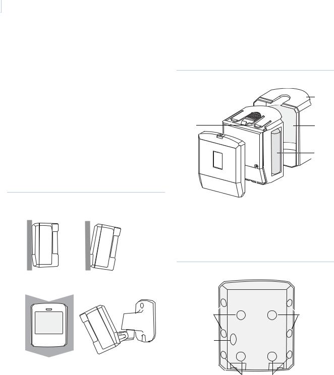
Figure 4. Sensor parts
Sensor
cover
Tabs |
Lens |
Battery
|
|
|
|
|
|
|
|
|
|
|
|
|
|
|
|
|
|
|
|
Tamper |
Sensor |
||
Mounting |
|||||
plate |
switch |
body |
|||
2.Punch out the mounting holes applicable for your installation (Figure 5). Use the lower-side holes for corner mounting, or the lower-back holes for surface-mounting with the standard lens. For applications with pets, use the upper mounting holes and the optional pet alley lens.
Figure 5. Mounting plate knockouts
Pet alley lens |
Pet alley lens |
knockouts |
knockouts |
Wall tamper |
|
knockout |
|
Standard lens knockouts
3.If you want wall-tamper functionality, remove the walltamper knockout (Figure 5).
4.Mark the location of the required holes on the mounting surface.
5.Use wall anchors and screws to secure the mounting plate in place. Attach the sensor to the mounting plate.
6.Test the sensor in place (see Testing on page 4), then screw the housing screw (the smallest screw provided) into the hole at the top of the mounting plate.
Loading...