


NX-475
Table of contents
 Loading...
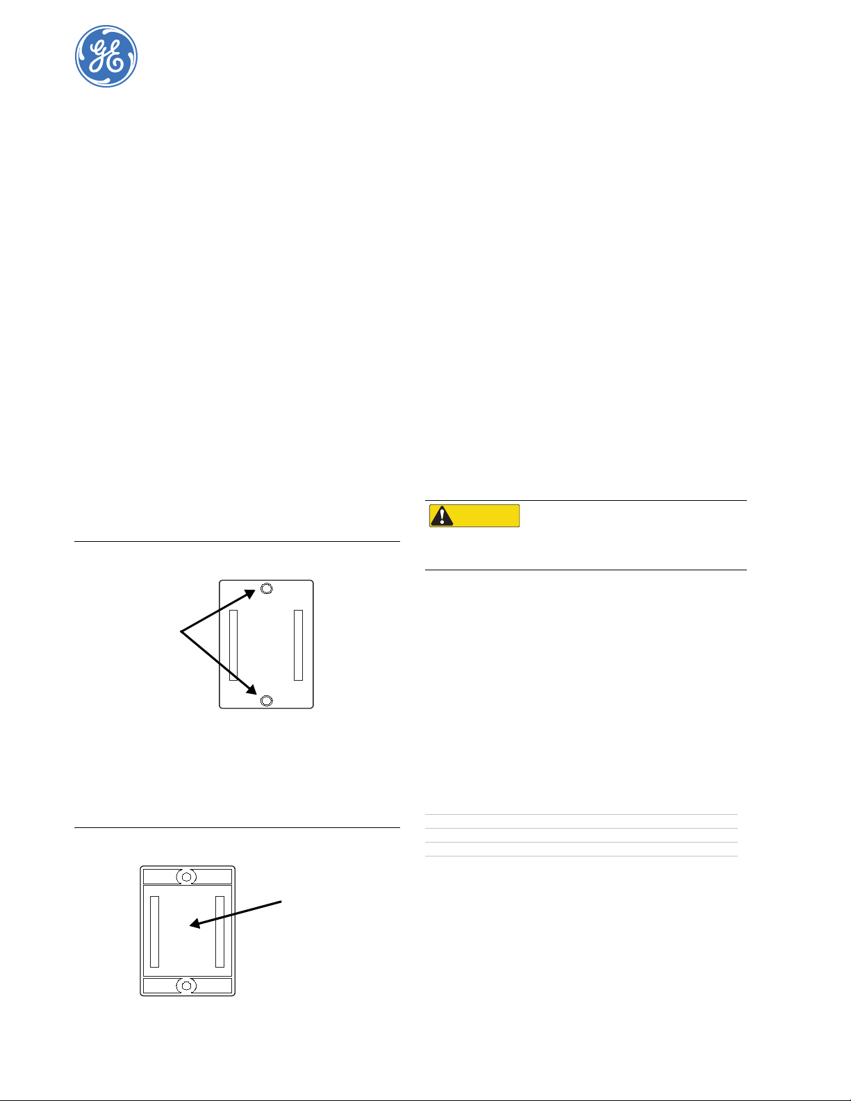
46-667 Rev. F
February 2005
Learn Mode Water-Resistant Pendant Panic Button
Installation Instructions
Product Summary
The Learn Mode panic button can be used throughout the home
to activate a police, medical, or auxiliary alarm. When the
sensor’s button is pressed, a built-in transmitter sends a signal to
the panel. The water-resistant design prevents damage in cases
where the sensor gets wet.
The sensor can be worn using a built-in belt clip or mounted on a
wall in a convenient location. For wall mounts, use Part No. 80-
116. Each kit includes the following:
• Five wall-mount holders
• Five pieces of double-sided tape
• 10 plastic anchors
• 10 Phillips-head screws
Installation Guidelines
• For wall mounts, select an easily accessible location.
• Although the panic button’s transmitter has an effective
range of at least 500 feet, the installation environment may
reduce this range.
Tools Needed
• Phillips screwdriver (for optional wall-mount holder)
Mounting with Anchors and Screws
1. Select a mounting location and mark the mounting hole
locations (see Figure 1).
Figure 1. Mounting Hole Locations
2. Mount the holder using the included anchors and screws.
Mounting with Double-Sided Tape
1. Peel the colored backing from the double-sided tape and
place on back of the holder (see Figure 2).
Figure 2. Placing Double-Sided Tape
2. Peel the second backing and press firmly to mounting
surface.
Programming the Sensor
This section describes the basic steps for adding a sensor to panel
memory. Refer to specific panel Installation Instructions for
complete details.
1. Set panel to Program Mode.
2. Enter the proper group number (00-07).
Note: For UL installations, the sensor must be added as a fixed
sensor type (Groups 00, 02, 04, or 05).
3. Select the desired sensor number.
4. Press the sensor button. The sensor trips.
5. Exit Program Mode.
Testing the Sensor
1. Set system to Dealer Sensor Test Mode.
2. Press the sensor button. Count the number of signals
received by the panel. Seven to eight signals is acceptable.
3. Test the sensor from various locations.
Replacing the Sensor Battery
1. Remove the two screws on the sensor’s back and separate
the front and back plastic.
2. Remove battery from holder and install the new battery.
Ensure to observe polarity.
Note: Do not substitute a different sized battery type.
3. Reassemble the sensor.
Note: To ensure water resistance, be especially careful not to
damage the sensor ’s rubber gasket lining.
4. Test the sensor.
Lithium Battery Disposal
Expired lithium batteries are considered hazardous waste. Be
sure to properly dispose of a used battery. Contact your local city
government for hazardous waste disposal laws.
Specifications
Notices
This device complies with part 15 of the FCC rules. Operation is subject
to the following two conditions:
1. This device may cause harmful interference.
2. This device must accept any interference received, including
interference that may cause undesired operation
Changes or modifications not expressly approved by GE Security can
void the user’s authority to operate the equipment.
Mounting
Holes
Place Tape
Here
CAUTION
You must be free of static electricity while
handling electronic components. Touch a
grounded bare metal surface before touching a
circuit board.
Model No. 60-578
Compatibility All GE Security Learn Mode panels
Power Source 3.6V Saft or Tekcell Lithium Battery
Enclosure Water-resistant and Shock-resistant
Dimensions 2-¼” x 1-¾” x ¾” (L x W x D)
Loading...