


600-1070

P/N 466-4434 • REV H • 13FEB15 1 / 9
Concord LCD Keypad with 2-Way Voice
Installation Sheet
Description
The Concord LCD Keypad with 2-Way Voice provides control
of all programming and operation of compatible security
systems.
The 2-line, 16-character display provides easy to read
messages to indicate the current status of the system. The
keypad includes police, fire, and auxiliary panic buttons that
can be activated anytime. An internal piezo provides system
status beeps for trouble and alarm indications.* Two-way audio
is achieved using an internal speaker and microphone
combination.*
A supervised hardwire zone provides an additional zone
without added wiring to the panel. Opening the removable
swing-down door reveals a label with basic system operating
commands.
* Not UL approved as a primary annunciator. Not investigated
for use as two-way verification.
Tools and Equipment needed
• 4-conductor, 18- or 22-gauge wire
• #2 Phillips screwdriver
• #6 screws and anchors (included)
• Screws for gang box installation
• Saw or utility knife for cutting wallboard
Installation
Installation Guidelines
• Mount the keypad in an environmentally controlled area
(32°F to 120°F/0°C to 49°C).
• When mounting the keypad, allow at least 6 inches below
it for the swing-down cover.
• When connecting two-way voice to the keypad, any
additional speaker devices on the system should be
connected in parallel with the keypad speaker connection.
Note: Siren volume will be reduced if connected in series.
This information differs from the information listed in the
Concord 4 Installation Manual.
• Do not exceed the maximum available power given in the
panel installation instructions.
• The hardwire zone is intended for use with intrusion
sensors only. This zone input does not provide power for
sensors such as PIRs, fire detectors, etc.
• Up to 16 keypads can be installed on a Concord 4 system
of which a maximum of two can be connected to two-way
audio or a single keypad plus an audio verification module.
Table 1: Keypad Power Usage
Current (mA)
Conditions
110
Maximum alarm current with the buzzer sounding
and the keypad illuminated from a button press
60
Typical operation
23
Power saving mode (no panel AC power)
Table 2: Maximum SuperBus and Audio Wire Lengths
Wire gauge (unshielded or
shielded)
Max. keypad wire length between
keypad and panel
18
750 feet
22
300 feet
Note: Interlogix recommends using shielded cable to prevent
crosstalk between the speaker and microphone.
Table 3: Maximum Hardwire Zone Wire Lengths
Wire gauge (unshielded or
shielded)
Max. keypad zone wire length
between keypad and sensor
22
100 feet
Hardwire zone End of Line (EOL) resistor should be 2K ohm.
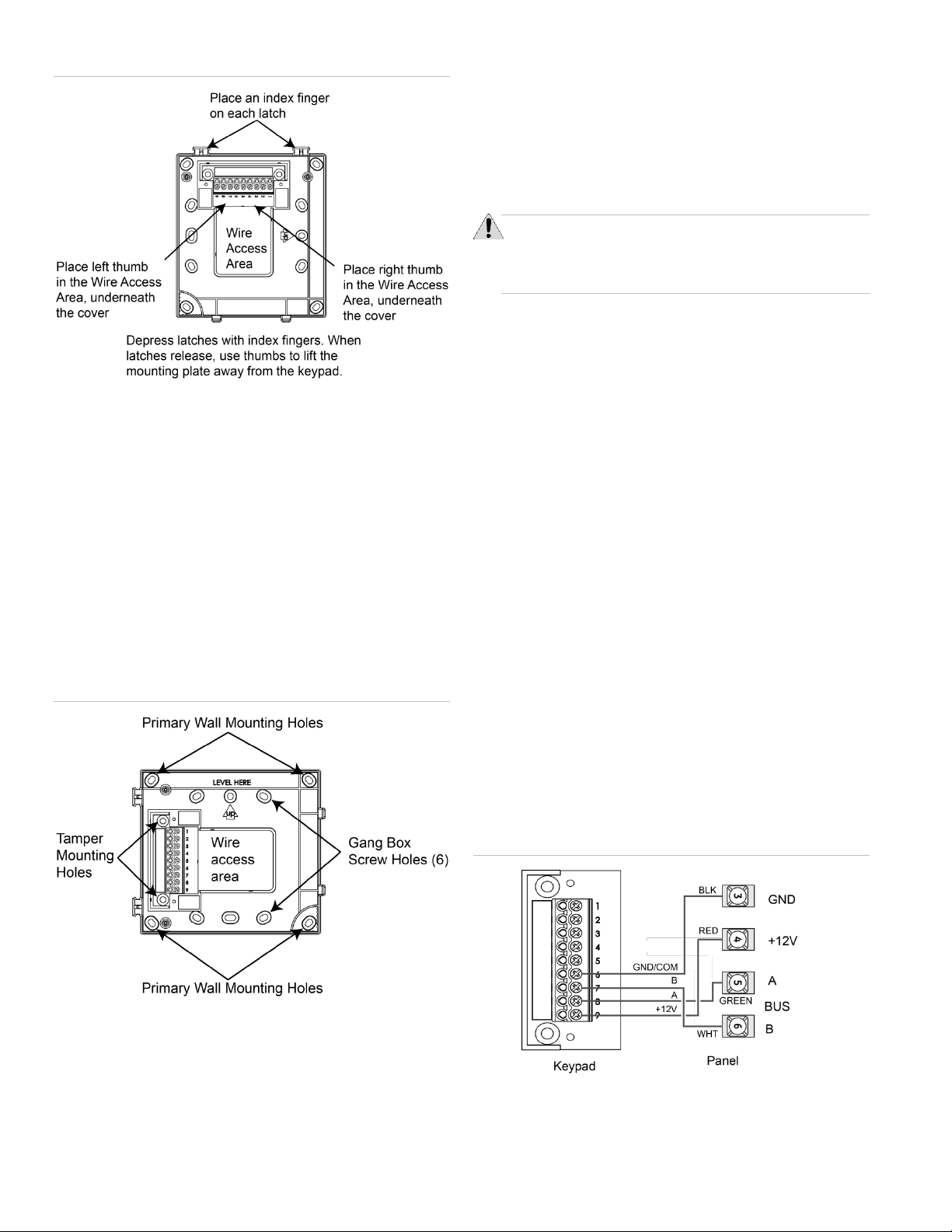
Installing the Mounting Plate
1. Place the keypad on a flat surface so that the mounting
plate is facing as shown in Figure 1 on page 2.
2. Remove the mounting plate from the keypad as described
in Figure 1 on page 2.
2 / 9 Concord LCD Keypad with 2-Way Voice Installation Sheet
Figure 1: Removing Mounting Plate From Keypad
3. Place the mounting plate on the wall and mark the primary
and tamper mounting holes, making sure to leave a 6 inch
clearance below the keypad for the door to open. See
Figure 2 below.
Note: Gang box mounting screws are not provided with
this keypad.
4. Insert anchors into the wall at the marked locations where
studs are not present.
5. Align the mounting plate over the selected mounting
locations and secure the back plate using the screws
provided.
Note: Do not over tighten screws or the mounting plate
may bind and prevent the keypad from mounting properly.
Figure 2: Marking the Mounting Holes
6. Cut a hole in the wall at the wire access area of the
mounting plate to pull the wiring cable through.
Optional Tamper Mounting
Note: Tamper mounting hardware is not supplied with this
product.
To enable the tamper function:
1. Remove the two small flathead screws that attach the
terminal block plate to the mounting plate.
2. Mount according to the process above.
Note: Tamper screws must be installed into a stud.
Wiring the Keypad
CAUTION: Use static electricity precautions when
handling electronic components.
Utiliser les précautions de l'électricite statique lors de la
manipulation des composants électroniques.
1. Remove the panel AC and backup battery power.
2. Run wires (18- or 22-gauge) from the panel and sensor to
the keypad location.
• 4-conductor (no 2-way voice) between panel and
keypad
• 8-conductor (with 2-way voice) between panel and
keypad
Note: Interlogix recommends using shielded cable to
prevent crosstalk between the speaker and
microphone.
• 2-conductor (to sensor) between keypad and hardwire
sensor (if installed)
3. When routing the wires, route all wiring connections from
the access area directly to the terminal, keeping wires
short and flat. No loops of wire should run outside the
access area.
Note: Do not run any excess wire outside the access area
as it will make the assembly of the keypad onto the
mounting plate difficult.
Wiring the Keypad – SB2000
1. Pull the ground, +12 volt and bus wires through the access
area.
2. Connect the Bus to the 9 position terminal block as shown
in Figure 3 below.
Figure 3: Connecting the Keypad
Note: For bus wire length over 150 feet, a 120 ohm
termination resistor is needed across A to B at the panel.
Concord LCD Keypad with 2-Way Voice Installation Sheet 3 / 9
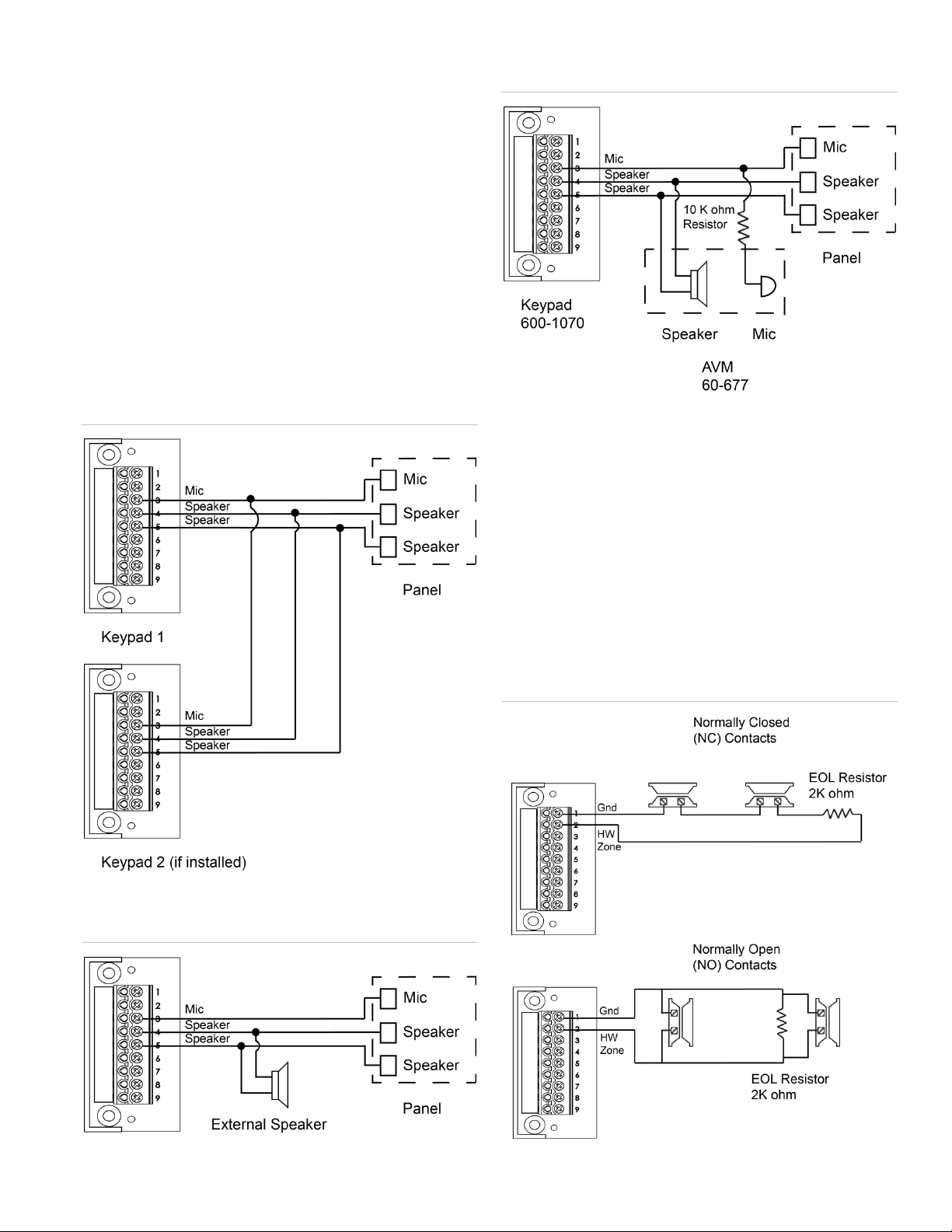
Wiring the Keypad – Speaker and Microphone
1. Pull the speaker and microphone wires through the access
area.
2. Connect the speaker and microphone wires to the 9
position terminal block as shown in Figure 4 below,
Figure 5 below and Figure 6 below.
3. If other audio devices will be installed on the system, wire
accordingly as shown in the following diagrams.
Note (1): Interlogix recommends using shielded cable to
prevent crosstalk between the speaker and microphone.
Note(2): The keypad is not UL approved as a primary
annunciator.
Note(3): Installations requiring an AVM in addition to the
Keypad Audio require the addition of a 10 K ohm resistor
(included) on the MIC wire of the AVM to equalize the MIC
performance of both devices.
Figure 4: Keypad to Audio Diagram (keypad only)
Figure 5: Keypad to Audio Diagram (multiple speakers)
Figure 6: Keypad to Audio Diagram (with Audio Verification
Module)
Wiring the Keypad – Hardwire Zone
1. Pull the hardwire zone wires through the access area.
2. Connect the hardwire zone wires to the 9 position terminal
block as shown in Figure 7 below.
3. Insert the end-of-line (EOL) resistor at the last device in
the loop. See Figure 7 below. Note: The EOL resistor
must be located at the last device in the loop.
4. Use a maximum of five contacts.
Note: The keypad does not supply power for sensors.
Sensor Zones must be of the normally open or closed
contact type.
Figure 7: Hardwire Zone
 Loading...