


 Loading...
SuperBus 2000 2X20 LCD Alphanumeric
Touchpad Installation Instructions
Product Summary
The SuperBus 2000® 2 x 20 LCD (liquid crystal display) Alphanumeric Touchpad gives you complete on-site system programming and operation control of a compatible security system (see the section “Specifications”).
A two-line, 40-character display provides visual system status messages. The display identifies any programmed location, allowing the user to determine where an alarm, trouble, or open-sensor condition exists.
Other features include:
•Touchpad buttons that light up after the first button press and remain lit until about 15 seconds after the last button press.
•Adjustable display contrast and backlighting.
•Built-in hardwire input (can be supervised with EOL resistor in SuperBus 2000 panels).
•Built-in door, which covers right-side buttons (60-809 only).
SuperBus 2000 Panels vs. SuperBus Panels
SuperBus 2000 panels assign module unit numbers automatically when the panel is powered up. This eliminates manually setting unit numbers and the chance of identical unit number conflicts.
SuperBus 2000 Panels
•Advent
•Concord (software versions 2.0 and newer)
•Concord Express
•Concord Ultra
SuperBus panels communicate with SuperBus 2000 modules but require the module unit number to be set manually. Touchpads automatically default to unit number 001.
SuperBus Panels
•UltraGard
•Concord (software versions 1.0–1.6)
Installation Guidelines
•For the maximum number of bus devices and touchpads per panel (see Table 1 below).
Table 1: Maximum Bus devices per panel
Panel |
Maximum Bus Devices |
|
|
Advent |
62 |
|
|
Ultragard |
8 |
|
|
Concord/Concord Express v4 |
16 |
|
|
Concord Express |
4 |
|
|
•Do not exceed the total panel output power when using panel power for bus devices, touchpads, and hardwired sensors that require it (see specific panel Installation Instructions).
•Maximum current draw from the touchpad is 120 mA.
•Minimum current draw from the touchpad when the panel is operating only on backup battery is 15 mA.
•Mount the touchpad in an environmentally controlled area (32° to 140° F) (0° to 60° C).
•When using the optional touchpad hardwire input, use only shielded wire (22-gauge or larger), and do not exceed the maximum wire length limits in Table 2 below between the touchpad and detection device.
Note: Shield wire must be connected to earth ground
Table 2: Hardwire input wire length limits
Gauge |
Max. wire length |
|
|
18 (shielded) |
1000 feet |
|
|
22 (shielded) |
350 feet |
|
|
•When mounting the touchpad back-plate, allow a 1-inch clearance on all sides since the touchpad is larger than the back-plate.
•Use 4-conductor, 22-gauge or larger stranded wire from the touchpad to the control panel.
P/N 466-1632 • REV D • 07APR11 |
1 |
• |
Follow the wire length limits outlined in the specific panel |
Figure 1: Touchpad mounting slots |
|
Installation Instructions between the touchpad and control |
MOUNTING SLOTS |
|
panel. |
|
|
|
The following must be observed in UL installations
•The touchpad hardwire input must not be used for fire alarm initiating devices.
•Only UL-listed devices may be connected to the touchpad hardwire input.
•The touchpad hardwire input can be configured for normally closed or normally open protection devices.
•For UL installations with UltraGard and Concord (software versions 1.0–1.6) panels, do not use the touchpad hardwire input.
Tools Needed
•Drill with bits
•Screwdrivers
•#6 screws and anchors (included)
•Panhead screws for a gang box installation
•Saw or utility knife for cutting wallboard
Note: Do not use screws larger than #6 or the touchpad will not seat properly onto the back-plate.
Installation
The touchpad can be installed on a wall or in a gang box.
To mount the touchpad on a wall:
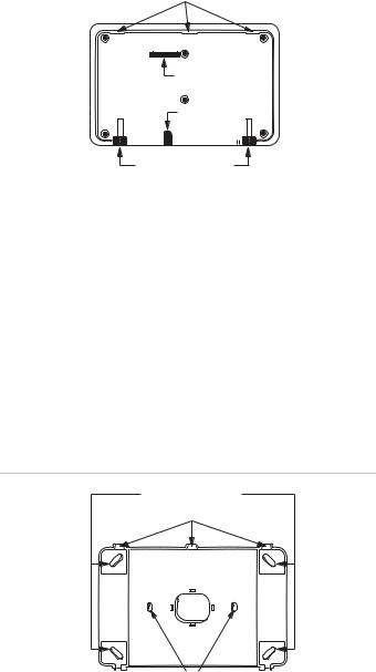
1.Separate the mounting bracket from the back-plate by loosening the two bottom screws and unlatching the tabs from the mounting slots (see Figure 1 below).
2.Place the back-plate on the wall and mark the four mounting holes and the wire access hole (see Figure 2 below). Be sure to leave a 1-inch clearance on all sides of the back-plate.
3.Drill holes and insert appropriate anchors.
4.Secure the back-plate to the wall with included screws.
5.Cut a hole in the wall where the wire access hole was marked to pull your cable through.
OPENING FOR CONNECTOR
CABLE OPENING
3101G03B.DSF
LOOSEN BOTTOM SCREWS (X2)
To mount the touchpad in a gang box:
1.Separate the mounting bracket from the back-plate by loosening the two bottom screws and unlatching the tabs from the mounting slots (see Figure 1 above).
2.Line up the gang box mounting holes with the holes on the gang box (see Figure 2 below).
3.Secure the back-plate to the gang box with panhead screws.
Note: Do not overtighten screws or the back-plate may bind and prevent the touchpad from mounting properly.
Figure 2: Back plate and mounting holes
WALL MOUNTING HOLES (X4)
BACK PLATE MOUNTING TABS (X3)
WIRE
ACCESS
HOLE
GANG BOX MOUNTING HOLES (X2)
Wiring
Wiring consists of connecting the touchpad wiring harness to the panel terminals. You may also connect an optional hardwire sensor to the touchpad hardwire input wires.
Before You Begin
1.Disconnect the panel AC power transformer and backup battery (turn off power switch on UltraGard panels).
2.Run a 4-conductor, 22-gauge wire cable from the panel to the touchpad location.
2 |
SuperBus 2000 2X20 LCD Alphanumeric Touchpad Installation Instructions |

3.Splice the 4-conductor cable wires to the matching colored wires located on the touchpad wiring harness.
Find your panel in the next section for specific wiring instructions.
Wiring Panels
Concord/Concord Express/Concord Ultra Panels
1.Connect the touchpad wiring to the panel terminals as shown in Figure 3 below. Wire multiple touchpads in parallel.
2.If desired, connect an optional hardwire switch to the yellow touchpad wires as shown in Figure 3 below.
Concord Express SystemsWire a 2K ohm EOL resistor (49-467) in series with normally closed switches and in parallel with normally open switches (see Figure 3 below).
Concord Systems with software version 2.0 or newerWire a 2K ohm EOL resistor (49-467) in series with normally closed switches and in parallel with normally open switches (see Figure 3 below).
Concord Systems with software versions 1.0–1.6 - This switch must be unsupervised and a resistor must not be used.
Note: The optional touchpad hardwire input must be added to panel memory. See the Concord/Concord Express panel Installation Instructions for setting the configuration.
3.Insert the touchpad wiring harness connector onto the pins located on the rear of the unit. Make sure the yellow wires are to the left, as shown.
Figure 3: Wiring the touchpad to Concord and Concord Express panels
|
PANEL TERMINALS |
|
||
OPTIONAL |
GND |
+12V |
BUS |
BUS |
BUS |
A |
B |
||
N/O SWITCH |
|
|
|
|
WITH MAGNET |
3 |
4 |
5 |
6 |
|
|
WHITE |
2K OHM |
|
GREEN |
EOL RESISTOR |
|
RED |
(Concord 2.0 or later |
|
BLACK |
and Concord |
Connect Shield |
|
Express panels) |
to Earth Ground |
|
OPTIONAL |
SHIELDED |
|
N/C SWITCH |
CABLE |
|
WITH MAGNET |
YELLOW |
|
|
|
|
|
|
NOT |
|
|
USED |
|
|
TAB |
|
|
SLOT (3) |
|
TOUCHPAD |
|
|
WIRING HARNESS |
|
|
49-430 |
|
Advent Panels
1.Splice the touchpad wiring to the panel SuperBus wiring harness as shown in Figure 4 below. Wire multiple touchpads in parallel.
2.If desired, connect an optional hardwire switch to the yellow wires on the touchpad wiring harness. Wire a 2K ohm EOL resistor (49-467) in series with normally closed switches and in parallel with normally open switches (see Figure 4 below).
Note: The optional touchpad hardwire input must be added to panel memory. See the Advent panel Installation Instructions for setting the configuration.
3.Insert the touchpad wiring harness connector onto the pins located on the rear of the unit. Make sure the yellow wires are to the left (see Figure 4 below).
Figure 4: Wiring the touchpad to Advent panels
|
|
|
|
|
|
TO ADDITIONAL |
||||
|
|
|
|
|
|
|
SUPERBUS |
|
||
|
|
|
|
|
|
|
TOUCHPADS |
|||
|
|
|
|
|
|
|
AND/OR |
|
||
|
|
|
|
|
|
|
MODULES |
|||
PANEL SUPERBUS |
(+12REDVDC) |
|||||||||
|
WIRING |
|||||||||
|
|
|
|
|
|
|
BLACK(GND) WHITE(BUSB) GREEN(BUSA) |
|||
HARNESS 49-462 |
|
|||||||||
|
|
|
|
|
|
|
|
|
|
|
|
|
|
|
|
|
|
|
|
|
|
|
|
|
|
|
|
|
|
|
|
|
OPTIONAL
N/O SWITCH
WITH MAGNET
|
SPLICE |
2K OHM |
Connect Shield |
EOL RESISTOR |
to Earth Ground |
OPTIONAL |
SHIELDED |
N/C SWITCH |
CABLE |
WITH MAGNET |
YELLOW |
NOT |
|
USED |
|
TAB |
|
SLOT |
(3) |
TOUCHPAD |
|
WIRING HARNESS |
|
49-430 |
|
UltraGard Panels
1.Connect the touchpad wiring to the panel terminals as shown in Figure 5 on page 4. Wire multiple touchpads in parallel.
2.If desired, connect an optional hardwire switch to the yellow touchpad wires as shown in Figure 5 on page 4 (unsupervised in UltraGard systems).
Note: The optional touchpad hardwire input must be added to panel memory. See the UltraGard panel
Installation Instructions or Reference Manual for setting the configuration.
3.Insert the touchpad wiring harness connector onto the pins located on the rear of the unit. Make sure the yellow wires are to the left
SuperBus 2000 2X20 LCD Alphanumeric Touchpad Installation Instructions |
3 |
Loading...