


NX-584 HOME AUTOMATION MODULE
Installation Manual
These instructions do not purport to cover all details or variations in equipment nor to provide every possible contingency to be met during installation, operation, and maintenance. If further information is desired or if particular problems arise that are not covered sufficiently for the purchaser’s purpose, the matter should be referred to GE Interlogix, Gladewater, Texas, USA.
This document contains proprietary information of GE Interlogix, USA and is furnished to its customer solely to assist that customer in the installation, testing, operations, and/or maintenance of the equipment described. This document shall not be reproduced in whole or in part nor shall its contents be disclosed to any third party without the written approval of GE Interlogix. Please refer to the current GE Interlogix product catalog for detailed warranty information.
TABLE OF CONTENTS |
|
|
I. |
GENERAL DESCRIPTION ................................................................................................. |
2 |
II. |
TERMINALS & PIN-OUT .................................................................................................... |
2 |
III. |
ENCLOSURE DIAGRAM.................................................................................................... |
3 |
IV. |
WIRING DIAGRAM............................................................................................................. |
4 |
V. |
ENROLLING THE MODULE............................................................................................... |
4 |
VI. |
PROGRAMMING THE MODULE........................................................................................ |
5 |
VII. |
PROGRAMMING DATA ..................................................................................................... |
5 |
VIII. |
LEDS INDICATORS............................................................................................................ |
6 |
IX. |
PROGRAMMING LOCATIONS .......................................................................................... |
7 |
X. |
PROGRAMMING WORKSHEETS.................................................................................... |
10 |
XI. |
SPECIFICATIONS ............................................................................................................ |
12 |
© 2003 GE Interlogix
NetworX is a trademark of GE Interlogix. All rights reserved.

I.GENERAL DESCRIPTION
The NetworX NX-584 is a low cost add-on module that fits neatly into any NetworX family system enclosure and provides a standard RS-232 bi-directional DB-9 connector for connection to a home automation host system. A simple three-wire connection to the main control is all that is required to fully integrate this card into the system.
The NX-584 has several levels of security that can be programmed in at the time of installation to allow as much or as little security system information to be passed to the host system. It can also be set to limit the commands that will be accepted from the host system to prevent unauthorized attempts to override the security system status.
The unit can be easily configured for communication in an ASCII or Binary protocol. A selectable baud rate can be set from 600 baud to 76.8k baud with hardware RTS and CTS handshaking. The ASCII implementation is easy to use and debug with standard programming tools while the Binary version is a more efficient for method for transferring information between the two systems. The system integrator can select any number of events or conditions to cause the NX-584 to send the relevant information to the host without polling. This allows for a faster response to activity than polling alone can provide.
All security system information can be requested at anytime if enabled to do so by the installer. This is useful at system initialization and at periodic intervals to keep the two systems in sync without worrying about missing any transitional event. This information is organized as System, Partition, Zones and Outputs. System information will contain such information as power status, phone line condition, module troubles, and other system wide condition. Partition information includes readiness of all zones assigned, armed state, entry / exit delays, last user number, alarm condition and many other conditions within a specific partition. Zone information includes faults, alarm memory, bypasses, troubles, tampers, low batteries, missing and partition assignments. Output messages include commands that can be passed to or from devices in X-10 compatible format.
II.TERMINALS & PIN-OUT
|
|
|
TERMINAL DESCRIPTIONS |
POS |
Connect to the KP POS terminal of the NX-8 |
COM |
Connect to the KP COM terminal of the NX-8 |
|
|
DATA |
Connect to the KP DATA terminal of the NX-8 |
|
|
|
|
2 |
NX-584 Home Automation |
DB-9 Pin-out
Signal |
Direction |
Jumper |
Pin Number |
|
Name |
NX------PC |
Number |
A Position |
B Position |
Cts* |
→ |
J7 |
8** |
7 |
Txd |
→ |
J8 |
2 |
3** |
Rts* |
← |
J9 |
8 |
7** |
Rxd |
← |
J10 |
2** |
3 |
Sig.Gnd. |
← → |
-- |
5 |
|
Unused |
-- |
-- |
1,4,6,9 |
|
*Note: Rts and Cts signals are not currently supported **Note: Default jumper settings
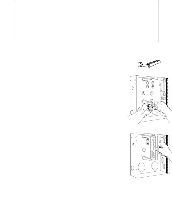
III. ENCLOSURE DIAGRAM
Inside the can, several 2-holed insertion points have been constructed. This allows for either vertical or horizontal placement of the modules. Notice that the insertion points have two sizes of holes -- a larger hole and a smaller hole.
Diagram 1: The black plastic PCB guides are grooved on one edge where the PC Board will be seated. The end with the half-moon protrusion fits into the larger hole. The smaller hole is for the screw.
Diagram 2: Place the first black plastic PCB guide in the top insertion point, grooved edge downward. The half-moon protrusion will be in the large hole. It does not require force. Insert one of the provided screws into the smaller hole (from inside the can) to secure it in place. A screwdriver should reach through the notch that runs the length of the guide to tighten the screw. The second PCB guide should be positioned opposite of the first (grooved edge up) and placed in the lower insertion point, using the same procedures described above. Once mounted, screw it in securely.
Diagram 3: The PC board should slide freely in the grooves of both guides.
NX-584 Home Automation |
3 |

IV. |
WIRING DIAGRAM |
|
|
|
|
|
|
CONNECT TO |
LEDS |
|
“A” Pos / |
“B” Pos |
|
|
|
|
||||
|
|
Jumpers |
J9 |
= 8 |
/ 7* |
|
|
|
|
||||
|
NX-8 TERMINALS |
|
|
|||
|
|
|
J7 |
= 8* / 7 |
||
|
|
|
|
|||
|
|
|
|
J10 |
= 2* / 3 |
|
|
|
|
|
J8 |
= 2 / 3* |
|
|
|
|
|
* Default Position |
||
DATA |
COM |
LED for circuit operation
only
POS
|
ATTACH THE HOST |
“B” “A” |
TO THIS CONNECTOR |
“B” |
“A” |
V.ENROLLING THE MODULE
The NetworX control panels have the ability to automatically find and store in memory the presence of all keypads, zone expanders, wireless receivers, output modules, and any other device on the keypad buss. This allows these devices to be supervised by the control panel. To enroll the devices, enter the Program Mode using the procedure outlined in the control panel Installation Manual. When the Program Mode is exited, the NX-8 control will automatically enroll the devices. The enrolling process takes about 12 seconds, during which time the AService@ LED will illuminate. User codes will not be accepted during the enrolling process. Once a module is enrolled, if it is not detected by the control, the AService@ LED will illuminate.
4 |
NX-584 Home Automation |
 Loading...