


 Loading...
UltraSyncTM Wi-Fi IP Camera
Installation Guide
P/N 466-5303-EN • REV A • ISS 25MAY17 © 2017 United Technologies Corporation. All rights reserved. 1
Contents |
|
Product overview..................................................................................... |
3 |
Installation environment........................................................................... |
3 |
Cable requirements.......................................................................... |
4 |
Package contents.................................................................................... |
4 |
UltraSync Wi-Fi IP Bullet Camera .................................................... |
4 |
UltraSync Wi-Fi IP Desktop Camera................................................ |
5 |
Camera description – Bullet Camera....................................................... |
6 |
Camera description – Desktop Camera................................................... |
7 |
Desktop camera LED indicators....................................................... |
8 |
Accessing the Micro SD card .................................................................. |
9 |
Bullet Camera .................................................................................. |
9 |
Desktop Camera .............................................................................. |
9 |
Mounting................................................................................................ |
10 |
Bullet Camera ................................................................................ |
10 |
Waterproof jacket assembly.......................................................... |
11 |
Desktop Camera ............................................................................ |
12 |
Browser requirements ........................................................................... |
13 |
Quick setup ........................................................................................... |
14 |
1. Setting up Ethernet/Wi-Fi transmission...................................... |
14 |
2. Add cameras to a Wi-Fi network ................................................ |
15 |
3. Add cameras to UltraSync.......................................................... |
17 |
4. Reboot cameras......................................................................... |
18 |
Alternative methods of adding cameras ................................................ |
18 |
Add cameras via Ethernet with a Windows PC .............................. |
18 |
Add cameras via WPS ................................................................... |
19 |
UltraSync app basic functions ............................................................... |
20 |
View Live Stream and Latest Clip .................................................. |
20 |
Program event triggered camera clips ........................................... |
20 |
View event triggered clips in History .............................................. |
22 |
Removing cameras from UltraSync................................................ |
22 |
Change default camera settings............................................................ |
23 |
TruVision Device Manager............................................................. |
23 |
TruVision Navigator........................................................................ |
23 |
Reset cameras to factory default........................................................... |
24 |
Reset button................................................................................... |
24 |
Camera configurator ...................................................................... |
24 |
Troubleshooting..................................................................................... |
25 |
Specifications........................................................................................ |
27 |
2 P/N 466-5303-EN • REV A • ISS 25MAY17 © 2017 United Technologies Corporation. All rights reserved.
Product overview
This is the installation guide for the following UltraSync IP camera models:
RS-3230/3231 (1080p IP Wi-Fi Desktop IR camera)
RS-3250/3251 (1080p IP Wi-Fi Bullet IR camera)
Installation environment
When installing the product, consider these factors:
Electrical: Electrical wiring should be installed carefully by qualified service personnel. Always use a proper Power over Ethernet (PoE) switch or a 12 VDC UL listed Class 2 or CE certified power supply to power the camera. Do not overload the power cord or adapter.
Ventilation: Ensure that the location planned for the installation of the camera is well ventilated.
Temperature: Do not operate the camera beyond the specified temperature, humidity, or power source ratings. The operating temperature of the camera is between -20 to +60°C (-4 to 140°F). Humidity is below 90%.
Moisture: Do not expose the camera to rain or moisture, or try to operate it in wet areas. Turn the power off immediately if the camera is wet and ask a qualified service person for servicing.
Moisture can damage the camera and also create the danger of electric shock.
Servicing: Do not attempt to service this camera yourself. Any attempt to dismantle or remove the covers from this product invalidates the warranty and may also result in serious injury. Refer all servicing to qualified service personnel.
Cleaning: Do not touch the sensor modules with fingers. If cleaning is necessary, use a clean cloth with some ethanol and wipe the camera gently. If the camera will not be used for an extended period of time, put on the lens cap to protect the sensors from dirt.
Reflectivity: Ensure that there is no reflective surface too close to the camera lens. The IR light from the camera may reflect back into the lens causing reflection.
P/N 466-5303-EN • REV A • ISS 25MAY17 © 2017 United Technologies Corporation. All rights reserved. 3
Cable requirements
For proper operation, adhere to the following cable and power requirements for the cameras. Category 5 cabling or better is recommended. All network cabling must be installed according to applicable codes and regulations.
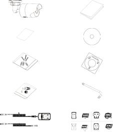
Package contents
Check the package and contents for visible damage. If any components are damaged or missing, do not attempt to use the unit; contact the supplier immediately. If the unit is returned, it must be shipped back in its original packaging.
UltraSync Wi-Fi IP Bullet Camera
IP Bullet Camera |
Installation Guide |
WEEE and Battery Installation |
Configuration CD |
Anchors and Screws |
Mounting Template |
Waterproof Jacket (Ethernet) |
Hex Wrench |
Power Supply and Extension |
Power Supply Adapters (US, |
|
EU, UK, and AUS) |
4 P/N 466-5303-EN • REV A • ISS 25MAY17 © 2017 United Technologies Corporation. All rights reserved.
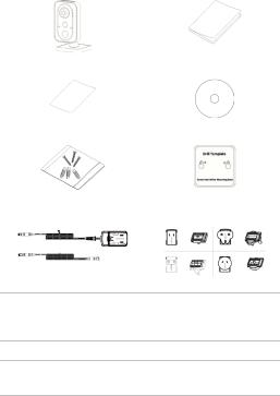
UltraSync Wi-Fi IP Desktop Camera
IP Desktop Camera |
Installation Guide |
WEEE and Battery Installation |
Configuration CD |
Anchors and Screws |
Mounting Template |
Power Supply and Extension |
Power Supply Adapters (US, |
|
EU, UK, and AUS) |
CAUTION: Use direct plug-in UL listed power supplies marked Class 2/CE certified or LPS (limited power source) of the required output rating as listed on the unit.
CAUTION: Risk of explosion if battery is replaced by an incorrect type. Dispose of used batteries according to the instructions.
P/N 466-5303-EN • REV A • ISS 25MAY17 © 2017 United Technologies Corporation. All rights reserved. 5
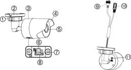
Camera description – Bullet Camera
1. |
Adjustment nut |
7. |
LED indicator |
2. |
Mounting base |
8. |
Micro SD card slot |
3. |
Main body |
9. |
Ethernet interface |
4. |
Sun shield |
10. |
Power cable (12 VDC) |
5. |
Lens |
11. |
GND screw |
6.WPS/RESET button
6 P/N 466-5303-EN • REV A • ISS 25MAY17 © 2017 United Technologies Corporation. All rights reserved.
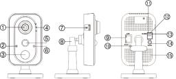
Camera description – Desktop Camera
1. |
Lens |
9. |
Ethernet interface |
2. |
Microphone |
10. |
WPS/RESET button |
3. |
IR (infrared) LED |
11. |
I: Alarm input interface |
4. |
LED indicators (see next |
12. |
G: Grounding |
|
page) |
13. |
O: Alarm output |
5. |
PIR (passive infrared) sensor |
|
interface |
6. |
Light sensor |
14. |
Power supply port |
7. |
Micro SD card slot |
|
(12 VDC) |
8. |
Three-axis bracket |
15. |
Speaker |
P/N 466-5303-EN • REV A • ISS 25MAY17 © 2017 United Technologies Corporation. All rights reserved. 7
Desktop camera LED indicators
The following table describes the desktop camera LED behavior (see item 4 in “Camera description – Desktop Camera” on page 7).
LED |
State |
Color |
Appearance |
|
|
|
|
Alarm |
Camera alarm triggered |
Red |
Solid |
|
|
|
|
|
Camera alarm not triggered |
Blue |
Solid |
|
|
|
|
Status |
UltraSync Service |
Blue |
Solid |
|
connected |
|
|
|
UltraSync Service |
None |
None |
|
disconnected |
|
|
Link |
WPS in process |
Blue |
Fast blinking |
|
|
|
|
|
Temporary Wi-Fi |
Blue |
Slow blinking |
|
connection enabled |
|
|
|
Ethernet communication |
Amber |
Blinking |
|
|
|
|
8 P/N 466-5303-EN • REV A • ISS 25MAY17 © 2017 United Technologies Corporation. All rights reserved.

Accessing the Micro SD card
A 16 GB Micro SD card is pre-installed in the camera. Micro SD cards with up to 128 GB of storage capacity can also be used.
Note: Video and log files stored on the Micro SD card can only be accessed using the UltraSync App when validated with the
UltraSync Panel.
Bullet Camera
To access the Micro SD card slot, remove the cover on the bottom of the camera.
Desktop Camera
P/N 466-5303-EN • REV A • ISS 25MAY17 © 2017 United Technologies Corporation. All rights reserved. 9
Mounting
Before mounting a camera:
Ensure that all the related equipment is powered off during the physical installation/camera mounting.
Ensure that the wall or ceiling is strong enough to withstand four times the weight of the camera assembly.
Bullet Camera
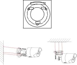
To mount the bullet camera on a wall or ceiling:
1.Drill the holes for the mounting hardware in the mounting surface using the supplied drill template. To route the cables from the base of the camera, drill a cable access hole in the mounting surface.
|
Ceiling Mounting |
Hole |
Hole |
|
Hole |
2.Route network cables to the mounting location as needed.
3.Secure the camera to the wall or ceiling with the supplied screws.
4.Connect the power cable and video output cable as needed.
5.Adjust the lens by doing the following: a. Loosen the adjustable nut.
10 P/N 466-5303-EN • REV A • ISS 25MAY17 © 2017 United Technologies Corporation. All rights reserved.
b.Adjust the pan direction [0°~360°].
c.Adjust the tilt direction [0°~90°].
d.Rotate the camera [0~360°] to adjust the lens to the surveillance angle.
e.Tighten the adjustable nut (1) to complete the installation.
Waterproof jacket assembly
We recommended using the waterproof jacket to protect network cabling when the camera is installed outdoors.
To assemble the waterproof jacket:
1.Remove the connector (3) from the end of the network cable
(7).
2.Route the network cable through the waterproof jacket components in the following sequence: fixed nut (6), waterproof ring (5), and the main body of the waterproof jacket
(4).
3.Insert the waterproof ring into the main body of the waterproof jacket.
4.Reattach the plug to the end of the network cable.
5.Place the O-ring (2) in the network interface (1) of the camera, and then connect the network cable.
6.Connect the network interface to the waterproof jacket, and then rotate the fixed nut clockwise to connect it to the main body of the waterproof jacket.
1. |
Network interface |
5. |
Waterproof ring |
2. |
O-ring |
6. |
Fixed nut |
3. |
Connector |
7. |
Network cable |
4.Waterproof jacket
P/N 466-5303-EN • REV A • ISS 25MAY17 © 2017 United Technologies Corporation. All rights reserved. 11
Loading...