


 Loading...
NS4802-24P-4S-2X User
Manual
P/N 1073040 • REV A • ISS 27AUG15

Copyright |
© 2015 UTC. All rights reserved. |
|
Interlogix is part of UTC Building & Industrial Systems, a unit of UTC. All rights |
|
reserved |
Trademarks and |
Trade names used in this document may be trademarks or registered |
patents |
trademarks of the manufacturers or vendors of the respective products. |
Manufacturer |
Interlogix |
|
2955 Red Hill Avenue, Costa Mesa, CA 92626-5923, USA |
|
Authorized EU manufacturing representative: |
|
UTC Fire & Security B.V. |
|
Kelvinstraat 7, 6003 DH Weert, The Netherlands |
FCC compliance |
Class A: This equipment has been tested and found to comply with the limits |
|
for a Class A digital device, pursuant to part 15 of the FCC Rules. These limits |
|
are designed to provide reasonable protection against harmful interference |
|
when the equipment is operated in a commercial environment. This equipment |
|
generates, uses, and can radiate radio frequency energy and, if not installed |
|
and used in accordance with the instruction manual, may cause harmful |
|
interference to radio communications. Operation of this equipment in a |
|
residential area is likely to cause harmful interference in which case the user will |
|
be required to correct the interference at his own expense. |
Canada |
This Class A digital apparatus complies with Canadian ICES-003. |
|
Cet appareil mumérique de la classe A est conforme à la norme NMB-003 du |
|
Canada. |
ACMA compliance |
Notice! This is a Class A product. In a domestic environment this product may |
|
cause radio interference in which case the user may be required to take |
|
adequate measures. |
Certification |
N4131 |
|
|
EU directives |
2004/108/EC (EMC directive): Hereby, UTC Fire & Security declares that this |
|
device is in compliance or with the essential requirements and other relevant |
|
provisions of Directive 2004/108/EC. |
|
2012/19/EU (WEEE directive): Products marked with this symbol cannot be |
|
disposed of as unsorted municipal waste in the European Union. For proper |
|
recycling, return this product to your local supplier upon the purchase of |
|
equivalent new equipment, or dispose of it at designated collection points. For |
|
more information see: www.recyclethis.info. |
|
2006/66/EC (battery directive): This product contains a battery that cannot be |
|
disposed of as unsorted municipal waste in the European Union. See the |
|
product documentation for specific battery information. The battery is marked |
|
with this symbol, which may include lettering to indicate cadmium (Cd), lead |
|
(Pb), or mercury (Hg). For proper recycling, return the battery to your supplier or |
|
to a designated collection point. For more information see: www.recyclethis.info. |
Contact information |
For contact information, see www.interlogix.com or |
|
www.utcfssecurityproducts.eu. |
2
|
TABLE OF CONTENTS |
|
1. INTRODUCTION.................................................................................................................. |
10 |
|
1.1 |
Packet Contents ......................................................................................................................................... |
10 |
1.2 |
Product Description ................................................................................................................................... |
11 |
1.3 How to Use This Manual ............................................................................................................................ |
15 |
|
1.4 |
Product Features........................................................................................................................................ |
16 |
1.5 |
Product Specifications .............................................................................................................................. |
19 |
2. INSTALLATION ................................................................................................................... |
22 |
|
2.1 |
Hardware Description ................................................................................................................................ |
22 |
|
2.1.1 Switch Front Panel .............................................................................................................................................. |
22 |
|
2.1.2 LED Indications ................................................................................................................................................... |
23 |
|
2.1.3 Switch Rear Panel............................................................................................................................................... |
24 |
2.2 |
Installing the Switch................................................................................................................................... |
25 |
|
2.2.1 Desktop Installation ............................................................................................................................................. |
25 |
|
2.2.2 Rack Mounting..................................................................................................................................................... |
26 |
|
2.2.3 Installing the SFP/SFP+ Transceiver................................................................................................................... |
26 |
2.3 |
Stack Installation ........................................................................................................................................ |
29 |
|
2.3.1 Connecting Stacking Cable.................................................................................................................................. |
31 |
|
2.3.2 Management Stacking......................................................................................................................................... |
32 |
3. SWITCH MANAGEMENT .................................................................................................... |
34 |
|
3.1 |
Requirements.............................................................................................................................................. |
34 |
3.2 Management Access Overview................................................................................................................. |
35 |
|
3.3 Administration Console............................................................................................................................. |
36 |
|
3.4 Web Management....................................................................................................................................... |
37 |
|
3.5 SNMP-based Network Management ......................................................................................................... |
37 |
|
4. WEB CONFIGURATION...................................................................................................... |
39 |
|
4.1 Main Web Page ........................................................................................................................................... |
41 |
|
4.2 |
System......................................................................................................................................................... |
43 |
|
4.2.1 System Information.............................................................................................................................................. |
44 |
|
3 |
|
4.2.2 IP Configuration................................................................................................................................................... |
45 |
4.2.3 IP Status .............................................................................................................................................................. |
47 |
4.2.4 Users Configuration............................................................................................................................................. |
48 |
4.2.5 Privilege Levels ................................................................................................................................................... |
51 |
4.2.6 NTP Configuration ............................................................................................................................................... |
52 |
4.2.7 Time Configuration .............................................................................................................................................. |
53 |
4.2.8 UPnP ................................................................................................................................................................... |
55 |
4.2.9 DHCP Relay ........................................................................................................................................................ |
56 |
4.2.10 DHCP Relay Statistics ....................................................................................................................................... |
58 |
4.2.11 CPU Load .......................................................................................................................................................... |
60 |
4.2.12 System Log........................................................................................................................................................ |
61 |
4.2.13 Detailed Log ...................................................................................................................................................... |
62 |
4.2.14 Remote Syslog .................................................................................................................................................. |
63 |
4.2.15 SMTP Configuration .......................................................................................................................................... |
64 |
4.2.16 Web Firmware Upgrade..................................................................................................................................... |
65 |
4.2.17 TFTP Firmware Upgrade ................................................................................................................................... |
66 |
4.2.18 Save Startup Config........................................................................................................................................... |
67 |
4.2.19 Configuration Download .................................................................................................................................... |
67 |
4.2.20 Configuration Upload......................................................................................................................................... |
68 |
4.2.21 Configuration Activate........................................................................................................................................ |
68 |
4.2.22 Configuration Delete.......................................................................................................................................... |
69 |
4.2.23 Image Select...................................................................................................................................................... |
69 |
4.2.24 Factory Default .................................................................................................................................................. |
70 |
4.2.25 System Reboot.................................................................................................................................................. |
71 |
4.3 Simple Network Management Protocol.................................................................................................... |
72 |
4.3.1 SNMP Overview .................................................................................................................................................. |
72 |
4.3.2 SNMP System Configuration............................................................................................................................... |
73 |
4.3.3 SNMP Trap Configuration.................................................................................................................................... |
75 |
4.3.4 SNMP System Information .................................................................................................................................. |
77 |
4.3.5 SNMPv3 Configuration........................................................................................................................................ |
78 |
4.3.5.1 SNMPv3 Communities .............................................................................................................................. |
78 |
4.3.5.2 SNMPv3 Users.......................................................................................................................................... |
79 |
4.3.5.3 SNMPv3 Groups........................................................................................................................................ |
80 |
4.3.5.4 SNMPv3 Views.......................................................................................................................................... |
81 |
4.3.5.5 SNMPv3 Access........................................................................................................................................ |
82 |
4.4 Port Management ....................................................................................................................................... |
84 |
4.4.1 Port Configuration................................................................................................................................................ |
84 |
4.4.2 Port Statistics Overview....................................................................................................................................... |
86 |
4.4.3 Port Statistics Detail............................................................................................................................................. |
87 |
4
4.4.4 SFP Module Information...................................................................................................................................... |
89 |
4.4.5 Port Mirror............................................................................................................................................................ |
90 |
4.5 Link Aggregation ........................................................................................................................................ |
93 |
4.5.1 Static Aggregation................................................................................................................................................ |
95 |
4.5.2 LACP Configuration............................................................................................................................................. |
96 |
4.5.3 LACP System Status ........................................................................................................................................... |
98 |
4.5.4 LACP Port Status................................................................................................................................................. |
99 |
4.5.5 LACP Port Statistics............................................................................................................................................. |
99 |
4.6 VLAN.......................................................................................................................................................... |
101 |
4.6.1 VLAN Overview ................................................................................................................................................. |
101 |
4.6.2 IEEE 802.1Q VLAN ........................................................................................................................................... |
101 |
4.6.3 VLAN Port Configuration ................................................................................................................................... |
105 |
4.6.4 VLAN Membership Status.................................................................................................................................. |
111 |
4.6.5 VLAN Port Status............................................................................................................................................... |
112 |
4.6.6 Port Isolation...................................................................................................................................................... |
114 |
4.6.7 VLAN setting example:...................................................................................................................................... |
116 |
4.6.7.1 Two Separate 802.1Q VLANs.................................................................................................................. |
116 |
4.6.7.2 VLAN Trunking between two 802.1Q aware switches ............................................................................. |
118 |
4.6.7.3 Port Isolate .............................................................................................................................................. |
121 |
4.6.8 MAC-based VLAN ............................................................................................................................................. |
122 |
4.6.9 Protocol-based VLAN........................................................................................................................................ |
123 |
4.6.10 Protocol-based VLAN Membership ................................................................................................................. |
124 |
4.7 Spanning Tree Protocol ........................................................................................................................... |
126 |
4.7.1 Theory ............................................................................................................................................................... |
126 |
4.7.2 STP System Configuration ................................................................................................................................ |
132 |
4.7.3 Bridge Status ..................................................................................................................................................... |
134 |
4.7.4 CIST Port Configuration..................................................................................................................................... |
135 |
4.7.5 MSTI Priorities................................................................................................................................................... |
138 |
4.7.6 MSTI Configuration............................................................................................................................................ |
139 |
4.7.7 MSTI Ports Configuration .................................................................................................................................. |
140 |
4.7.8 Port Status......................................................................................................................................................... |
142 |
4.7.9 Port Statistics..................................................................................................................................................... |
143 |
4.8 Multicast .................................................................................................................................................... |
144 |
4.8.1 IGMP Snooping ................................................................................................................................................. |
144 |
4.8.2 Profile Table....................................................................................................................................................... |
148 |
4.8.3 Address Entry .................................................................................................................................................... |
149 |
4.8.4 IGMP Snooping Configuration........................................................................................................................... |
150 |
4.8.5 IGMP Snooping VLAN Configuration................................................................................................................. |
152 |
5
4.8.6 IGMP Snooping Port Group Filtering ................................................................................................................. |
154 |
4.8.7 IGMP Snooping Status ...................................................................................................................................... |
155 |
4.8.8 IGMP Group Information.................................................................................................................................... |
156 |
4.8.9 IGMPv3 Information........................................................................................................................................... |
157 |
4.8.10 MLD Snooping Configuration........................................................................................................................... |
158 |
4.8.11 MLD Snooping VLAN Configuration................................................................................................................. |
159 |
4.8.12 MLD Snooping Port Group Filtering................................................................................................................. |
161 |
4.8.13 MLD Snooping Status...................................................................................................................................... |
162 |
4.8.14 MLD Group Information ................................................................................................................................... |
163 |
4.8.15 MLDv2 Information .......................................................................................................................................... |
164 |
4.8.16 MVR (Multicaset VLAN Registration)............................................................................................................... |
165 |
4.8.17 MVR Status...................................................................................................................................................... |
168 |
4.8.18 MVR Groups Information................................................................................................................................. |
169 |
4.8.19 MVR SFM Information ..................................................................................................................................... |
169 |
4.9 Quality of Service ..................................................................................................................................... |
171 |
4.9.1 Understanding QoS........................................................................................................................................... |
171 |
4.9.2 Port Policing ...................................................................................................................................................... |
172 |
4.9.3 Port Classification.............................................................................................................................................. |
172 |
4.9.4 Port Scheduler................................................................................................................................................... |
174 |
4.9.5 Port Shaping...................................................................................................................................................... |
175 |
4.9.5.1 QoS Egress Port Schedule and Shapers ................................................................................................ |
176 |
4.9.6 Port Tag Remarking........................................................................................................................................... |
177 |
4.9.6.1 QoS Egress Port Tag Remarking............................................................................................................. |
178 |
4.9.7 Port DSCP......................................................................................................................................................... |
179 |
4.9.8 DSCP-based QoS ............................................................................................................................................. |
180 |
4.9.9 DSCP Translation.............................................................................................................................................. |
181 |
4.9.10 DSCP Classification......................................................................................................................................... |
182 |
4.9.11 QoS Control List............................................................................................................................................... |
183 |
4.9.11.1 QoS Control Entry Configuration ........................................................................................................... |
185 |
4.9.12 QCL Status ...................................................................................................................................................... |
187 |
4.9.13 Storm Control Configuration ............................................................................................................................ |
188 |
4.9.14 WRED.............................................................................................................................................................. |
189 |
4.9.15 QoS Statistics .................................................................................................................................................. |
192 |
4.9.16 Voice VLAN Configuration ............................................................................................................................... |
192 |
4.9.17 Voice VLAN OUI Table..................................................................................................................................... |
195 |
4.10 Access Control Lists.............................................................................................................................. |
196 |
4.10.1 Access Control List Status ............................................................................................................................... |
196 |
4.10.2 Access Control List Configuration.................................................................................................................... |
198 |
4.10.3 ACE Configuration........................................................................................................................................... |
200 |
6
4.10.4 ACL Ports Configuration .................................................................................................................................. |
210 |
4.10.5 ACL Rate Limiter Configuration ....................................................................................................................... |
212 |
4.11 Authentication......................................................................................................................................... |
213 |
4.11.1 Understanding IEEE 802.1X Port-Based Authentication.................................................................................. |
214 |
4.11.2 Authentication Configuration............................................................................................................................ |
217 |
4.11.3 Network Access Server Configuration.............................................................................................................. |
218 |
4.11.4 Network Access Overview ............................................................................................................................... |
229 |
4.11.5 Network Access Statistics ................................................................................................................................ |
230 |
4.11.6 RADIUS ........................................................................................................................................................... |
237 |
4.11.7 TACACS+ ........................................................................................................................................................ |
239 |
4.11.8 RADIUS Overview ........................................................................................................................................... |
240 |
4.11.9 RADIUS Details ............................................................................................................................................... |
242 |
4.11.10 Windows Platform RADIUS Server Configuration.......................................................................................... |
248 |
4.11.11 802.1X Client Configuration ........................................................................................................................... |
253 |
4.12 Security ................................................................................................................................................... |
256 |
4.12.1 Port Limit Control............................................................................................................................................. |
256 |
4.12.2 Access Management ....................................................................................................................................... |
260 |
4.12.3 Access Management Statistics ........................................................................................................................ |
261 |
4.12.4 HTTPs ............................................................................................................................................................. |
262 |
4.12.5 SSH................................................................................................................................................................. |
263 |
4.12.6 Port Security Status......................................................................................................................................... |
263 |
4.12.7 Port Security Detail.......................................................................................................................................... |
266 |
4.12.8 DHCP Snooping .............................................................................................................................................. |
267 |
4.12.9 Snooping Table................................................................................................................................................ |
268 |
4.12.10 IP Source Guard Configuration...................................................................................................................... |
269 |
4.12.11 IP Source Guard Static Table......................................................................................................................... |
270 |
4.12.12 ARP Inspection.............................................................................................................................................. |
271 |
4.12.13 ARP Inspection Static Table........................................................................................................................... |
272 |
4.1 Address Table ........................................................................................................................................... |
274 |
4.13.1 MAC Table Configuration................................................................................................................................. |
274 |
4.13.2 MAC Address Table Status .............................................................................................................................. |
276 |
4.13.3 Dynamic ARP Inspection Table........................................................................................................................ |
277 |
4.13.4 Dynamic IP Source Guard Table...................................................................................................................... |
278 |
4.14 LLDP ........................................................................................................................................................ |
280 |
4.14.1 Link Layer Discovery Protocol ......................................................................................................................... |
280 |
4.14.2 LLDP Configuration ......................................................................................................................................... |
280 |
4.14.3 LLDP MED Configuration ................................................................................................................................ |
283 |
4.14.4 LLDP-MED Neighbor....................................................................................................................................... |
289 |
7
4.14.5 Neighbor.......................................................................................................................................................... |
293 |
|
4.14.6 Port Statistics................................................................................................................................................... |
294 |
|
4.15 Network Diagnostics.............................................................................................................................. |
296 |
|
4.15.1 Ping ................................................................................................................................................................. |
|
297 |
4.15.2 IPv6 Ping ......................................................................................................................................................... |
298 |
|
4.15.3 Remote IP Ping Test........................................................................................................................................ |
299 |
|
4.15.4 Cable Diagnostics............................................................................................................................................ |
300 |
|
4.16 Power over Ethernet .............................................................................................................................. |
302 |
|
4.16.1 Power over Ethernet Powered Device............................................................................................................. |
302 |
|
4.16.2 System Configuration ...................................................................................................................................... |
304 |
|
4.16.3 Power Over Ethernet Configuration................................................................................................................. |
305 |
|
4.16.4 Port Sequential................................................................................................................................................ |
307 |
|
4.16.5 Port Configuration............................................................................................................................................ |
308 |
|
4.16.6 PoE Status....................................................................................................................................................... |
310 |
|
4.16.7 PoE Schedule.................................................................................................................................................. |
312 |
|
4.16.8 LLDP PoE Neighbours..................................................................................................................................... |
315 |
|
4.17 Loop Protection...................................................................................................................................... |
316 |
|
4.17.1 Configuration ................................................................................................................................................... |
316 |
|
4.17.2 Loop Protection Status..................................................................................................................................... |
317 |
|
4.18 RMON....................................................................................................................................................... |
|
319 |
4.18.1 RMON Alarm Configuration ............................................................................................................................. |
319 |
|
4.18.2 RMON Alarm Status......................................................................................................................................... |
321 |
|
4.18.3 RMON Event Configuration ............................................................................................................................. |
322 |
|
4.18.4 RMON Event Status......................................................................................................................................... |
323 |
|
4.18.5 RMON History Configuration ........................................................................................................................... |
324 |
|
4.18.6 RMON History Status....................................................................................................................................... |
325 |
|
4.18.7 RMON Statistics Configuration ........................................................................................................................ |
326 |
|
4.18.8 RMON Statistics Status.................................................................................................................................... |
327 |
|
4.19 Stack ........................................................................................................................................................ |
|
329 |
4.19.1 Stack................................................................................................................................................................ |
|
331 |
4.19.1.1 |
Switch IDs........................................................................................................................................... |
331 |
4.19.1.2 |
Master Election ................................................................................................................................... |
332 |
4.19.1.3 |
Stack Redundancy.............................................................................................................................. |
332 |
4.19.1.4 |
Shortest Path Forwarding ................................................................................................................... |
333 |
4.19.2 Stack Configuration.......................................................................................................................................... |
333 |
|
4.19.3 Stack Information............................................................................................................................................. |
337 |
|
4.19.4 Stack Port State Overview ............................................................................................................................... |
338 |
|
4.19.5 Stack Example................................................................................................................................................. |
338 |
|
8
5. SWITCH OPERATION ....................................................................................................... |
342 |
|
5.1 Address Table ........................................................................................................................................... |
342 |
|
5.2 |
Learning .................................................................................................................................................... |
342 |
5.3 |
Forwarding & Filtering ............................................................................................................................. |
342 |
5.4 |
Store-and-Forward ................................................................................................................................... |
342 |
5.5 Auto-Negotiation ...................................................................................................................................... |
343 |
|
6. TROUBLESHOOTING....................................................................................................... |
344 |
|
APPENDIX A: Networking Connection ............................................................................... |
345 |
|
A.1 |
PoE RJ-45 Port Pin Assignments........................................................................................................... |
345 |
A.2 |
Switch's Data RJ-45 Pin Assignments - 1000Mbps, 1000BASE-T ...................................................... |
345 |
A.3 |
10/100Mbps, 10/100BASE-TX.................................................................................................................. |
345 |
APPENDIX B : GLOSSARY .................................................................................................. |
347 |
|
9

1. INTRODUCTION
Thank you for purchasing a NS4802-24P-4S-2X L2+ 24-Port 10/100/1000T 802.3at PoE + 4-Port Shared SFP + 2-Port 10G SFP+ Managed Stackable Switch. NS4802-24P-4S-2X, comes with the multi-port Gigabit Ethernet Switch and SFP fiber optic connectibility and robust layer 2 features. The description of this model is shown below:
NS4802-24P-4S-2X L2+ 24-Port 10/100/1000T 802.3at PoE + 4-Port Shared SFP + 2-Port 10G SFP+ Managed Stackable Switch
“Managed Switch” “NS4802” is used as an alternative name in this user’s manual.
1.1 Packet Contents
Open the box of the Managed Switch and carefully unpack it. The box should contain the following items:
Managed Switch |
x 1 |
Quick Installation Guide |
x 1 |
RJ45 to RS232 Cable |
x 1 |
SFP Dusty Cap |
x 8 |
Rubber Feet |
x 4 |
Rack-mount Accessory Kit |
x 1 |
Power Cord |
x 1 |
If any of these are missing or damaged, please contact your dealer immediately; if possible, retain the carton including the original packing material, and use them again to repack the product in case there is a need to return it to us for repair.
10
1.2 Product Description
High-Density, Resilient Deployment Switch Solution for Gigabit Networking of Enterprise, Campus and Data Center
For the growing Gigabit network and IoT (Internet of Things) demand, IFS has launched a new-generation Stackable Gigabit PoE+ Switch solution, the NS4802-24P-4S-2X, to meet the needs of IP surveillance, enterprises, telecoms and campuses for a large-scale network deployment. The NS4802-24P-4S-2X is Layer 2+ Managed Stackable Gigabit PoE+ Switch, which supports both IPv4 and IPv6 protocols and hardware Layer 3 static routing capability, and provides 24 10/100/1000Mbps Gigabit Ethernet ports, 4 shared Gigabit SFP slots, 2 10G SFP+ uplink slots and another 2 dedicated 10G SFP+ stacked interfaces for stacking the switch. Up to 16 units, 384 Gigabit Ethernet ports and 32 10Gbps SFP+ slots can be managed by a stacking group and you can add ports and functionality as needed.
Efficient Single IP Management
The NS4802-24P-4S-2X applies the advantage of the stacking technology to managing the stack group with one single IP address, which helps network managers to easily manage a stack of switches instead of connecting and setting each unit one by one. The stacking technology also enables the chassis-based switches to be integrated into the NS4802-24P-4S-2X Managed Switch at an inexpensive cost.
11
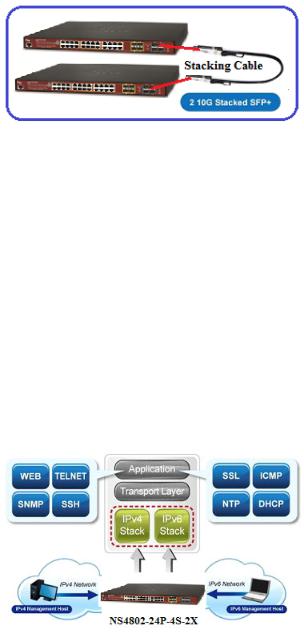
Highly-reliable Stacking Ability
Through its up to 40Gbps, bi-directional high bandwidth tunnel and stacking technology, the NS4802 gives the enterprises, service providers and telecoms flexible control over port density, uplinks and switch stack performance. The stack redundancy of the NS4802 ensures that data integrity is retained even if one switch in the stack fails. You can even hot-swap switches without disrupting the network, which greatly simplifies the tasks of upgrading the LAN for catering to increasing bandwidth demands.
Cost-effective 10Gbps Uplink Capacity
10G Ethernet is a big leap in the evolution of Ethernet. The two 10G SFP+ slot of the NS4802 supports Dual-speed, 10GBASE-SR/LR or 1000BASE-SX/LX, meaning the administrator now can flexibly choose the suitable SFP/SFP+ transceiver according to the transmission distance or the transmission speed required to extend the network efficiently. They greatly support SMB network to achieve 10Gbps high performance in a cost-effective way because 10GbE interface usually could be available in Layer 3 Switch but Layer 3 Switch could be too expensive to SMBs. (Small Businesses)
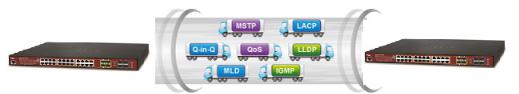
Solution for IPv6 Networking
By supporting IPv6 / IPv4 dual stack and plenty of management functions with easy and friendly management interfaces, the NS4802 is the best choice for IP surveillance, VoIP and wireless service providers to connect with the IPv6 network. It also helps the SMB to step in the IPv6 era with the lowest investment but not necessary to replace the network facilities while the ISP constructs the IPv6 FTTx edge network.
IPv4 and IPv6 VLAN Routing for Secure and Flexible Management
To help customers stay on top of their businesses, the NS4802 not only provides ultra high transmission performance and excellent layer 2 technologies, but also offers IPv4/IPv6 VLAN routing feature which allows crossing over different VLANs and different IP addresses for the purpose of having a highly secured, flexible management and simpler networking application.
Robust Layer2 Features
12
The NS4802 can be programmed for advanced switch management function, such as dynamic port link aggregation, Q-in-Q VLAN, Multiple spanning tree protocol (MSTP), Layer 2/4 QoS, bandwidth control and IGMP/MLD snooping. The NS4802 allows the operation of a high-speed trunk combining multiple ports. It enables up to 3 groups of 6 ports for trunk maximum and supports connection fail-over as well.
Powerful Security
The NS4802-24P-4S-2X offers comprehensive layer2 to layer4 access control list (ACL) for enforcing security to the edge. It can be used to restrict to network access by denying packets based on source and destination IP address, TCP/UDP port number or defined typical network applications. Its protection mechanism also comprises 802.1x Port-based and MAC-based user and device authentication. With the private VLAN function, communication between edge ports can be prevented to ensure user privacy.
Enhanced Security and Traffic Control
The NS4802-24P-4S-2X also provides DHCP Snooping, IP Source Guard and Dynamic ARP Inspection functions to prevent IP snooping from attack and discard ARP packets with invalid MAC address. The network administrator can now construct highly secured corporate networks with considerably less time and effort than before.
User-friendly Secure Management
For efficient management, the NS4802-24P-4S-2X managed switch is equipped with console, web and SNMP management interfaces. With the built-in web-based management interface, the NS4802-24P-4S-2X offers an easy-to-use, platform independent management and configuration facility. The NS4802-24P-4S-2X supports SNMP and it can be managed via any management software based on standard of SNMP v1 and v2 protocol. For reducing product learning time, the NS4802-24P-4S-2X offers Cisco-like command via Telnet or console port and customer doesn’t need to learn new command from these switches. Moreover, the NS4802-24P-4S-2X offers remote secure management by supporting SSH, SSL and SNMPv3 connection which can be encrypted the packet content at each session.
Flexible and Extendable Solution
The 4 mini-GBIC SFP slots built in the NS4802-24P-4S-2X support dual speed as it features 100BASE-FX and 1000BASE-SX/LX SFP (Small Form-factor Pluggable) fiber-optic modules. Now the administrator can flexibly choose the suitable SFP transceiver according to not only the transmission distance, but also the transmission speed required. The distance can be extended from 550 meters to 2km (multi-mode fiber) and up to above 10/20/30/40/50/70 kilometers (single-mode fiber or WDM fiber). They are well suited for applications within the enterprise data centers and distributions.
Intelligent SFP Diagnosis Mechanism
The NS4802 supports SFP-DDM (Digital Diagnostic Monitor) function that greatly helps network administrator to easily monitor real-time parameters of the SFP and SFP+ transceivers, such as optical output power, optical input power, temperature, laser bias current, and transceiver supply voltage.
13

Centralized Power Management for Gigabit Ethernet PoE Networking
To fulfill the needs of higher power required PoE network applications with Gigabit speed transmission, the NS4802 features high-performance Gigabit IEEE 802.3af PoE (up to 15.4 watts) and IEEE 802.3at PoE+ (up to 30 watts) on all ports. It perfectly meets the power requirement of PoE VoIP phone and all kinds of PoE IP cameras such as IR, PTZ, speed dome cameras or even box type IP cameras with built-in fan and heater for high power consumption.
The NS4802’s PoE capabilities also help to reduce deployment costs for network devices as a result of freeing from restrictions of power outlet locations. Power and data switching are integrated into one unit, delivered over a single cable and managed centrally. It thus eliminates cost for additional AC wiring and reduces installation time.
Built-in Unique PoE Functions for Surveillance Management
As a managed PoE Switch for surveillance network, the NS4802 features intelligent PoE Management functions:
Scheduled Power Recycling
SMTP/SNMP Trap Event Alert
PoE Schedule
Scheduled Power Recycling
The NS4802 allows each of the connected PD (Powered Device) to reboot in a specific time each week. Therefore, it will reduce the chance of PD (Powered Device) crash resulting from buffer overflow.
SMTP/SNMP Trap Event alert
Though most NVR or camera management software offer SMTP email alert function, the NS4802 further provides event alert function to help to diagnose the abnormal device owing to whether or not there is a break of the network connection, loss of PoE power or the rebooting response by PD Alive Check process.
PoE Schedule for Energy Saving
Besides being used for IP surveillance, theNS4802 is certainly applicable to construct any PoE network including VoIP and wireless LAN. Under the trend of energy saving worldwide and contributing to the environmental protection on the Earth, the NS4802 can effectively control the power supply besides its capability of giving high watts power. The “PoE schedule” function helps you to enable or disable PoE power feeding for each PoE port during specified time intervals and it is a powerful function to help SMBs or enterprises save power and money.
14
1.3 How to Use This Manual
This User’s Manual is structured as follows: Section 2, INSTALLATION
The section explains the functions of the Managed Switch and how to physically install the Managed Switch.
Section 3, SWITCH MANAGEMENT
The section contains the information about the software function of the Managed Switch.
Section 4, WEB CONFIGURATION
The section explains how to manage the Managed Switch by Web interface.
Section 5, SWITCH OPERATION
The chapter explains how to do the switch operation of the Managed Switch.
Section 6, POWER over ETHERNET OVERVIEW
The chapter introduces the IEEE 802.3af / 802.3at PoE standard and PoE provision of the Managed Switch.
Section 7, TROUBLESHOOTING
The chapter explains how to do troubleshooting of the Managed Switch.
Appendix A
The section contains cable information of the Managed Switch.
15

1.4 Product Features
Physical Port
24-Port 10/100/1000BASE-T RJ45 copper with IEEE 802.3at / 802.3af Power over Ethernet Injector function
4 100/1000BASE-X mini-GBIC/SFP slots, shared with Port-21 to Port-24 compatible with 100BASE-FX SFP
2 10GBASE-SR/LR SFP+ slots, compatible with 1000BASE-SX/LX/BX SFP
2 10GBASE-SR/LR SFP+ stacking slots
RJ45 console interface for basic management and setup
Stacking Features
■Physical stacking up to 16 units, 384 Gigabit ports, 32 10 Gigabit ports
■Single IP address stack management
■Stacking architecture supports Chain and Ring mode
■Plug and Play connectivity
■Mirror across stack
■Link Aggregation groups spanning multiple switches in a stack
■Physical MAC address learning with MAC table synchronization across stack
Layer 2 Features
■Prevents packet loss with back pressure (half-duplex) and IEEE 802.3x pause frame flow control (full-duplex)
■High performance of Store-and-Forward architecture and runt/CRC filtering eliminates erroneous packets to optimize the network bandwidth
■Storm Control support
−Broadcast / Multicast / Unknown unicast
■Supports VLAN
−IEEE 802.1Q tagged VLAN
−Up to 255 VLANs groups, out of 4094 VLAN IDs
−Supports provider bridging (VLAN Q-in-Q, IEEE 802.1ad)
−Private VLAN Edge (PVE)
−Protocol-based VLAN
−MAC-based VLAN
−Voice VLAN
■Supports Spanning Tree Protocol
−STP, IEEE 802.1D Spanning Tree Protocol
−RSTP, IEEE 802.1w Rapid Spanning Tree Protocol
−MSTP, IEEE 802.1s Multiple Spanning Tree Protocol, spanning tree by VLAN
−BPDU Guard
■Supports Link Aggregation
−802.3ad Link Aggregation Control Protocol (LACP)
−Cisco ether-channel (Static Trunk)
−Maximum 10 trunk groups, up to 16 ports per trunk group
−Up to 32Gbps bandwidth (full duplex mode)
■Provides port mirror (many-to-1)
■Port mirroring to monitor the incoming or outgoing traffic on a particular port
■Loop protection to avoid broadcast loops
Layer 3 IP Routing Features
Supports maximum 128 VLAN interfaces
32 static routing entries
Quality of Service
16

■Ingress Shaper and Egress Rate Limit per port bandwidth control
■8 priority queues on all switch ports
■Traffic classification
-IEEE 802.1p CoS
-TOS / DSCP / IP Precedence of IPv4/IPv6 packets
-IP TCP/UDP port number
-Typical network application
■Strict priority and Weighted Round Robin (WRR) CoS policies
■Supports QoS and In/Out bandwidth control on each port
■Traffic-policing policies on the switch port
■DSCP remarking
Multicast
Supports IGMP Snooping v1, v2 and v3
Supports MLD Snooping v1 and v2
Querier mode support
IGMP Snooping port filtering
MLD Snooping port filtering
Multicast VLAN Registration (MVR) support
Security
Authentication
-IEEE 802.1x Port-based / MAC-based network access authentication
-Built-in RADIUS client to co-operate with the RADIUS servers
-TACACS+ login users access authentication
-RADIUS / TACACS+ users access authentication
Access Control List
-IP-based Access Control List (ACL)
-MAC-based Access Control List
Source MAC / IP address binding
DHCP Snooping to filter un-trusted DHCP messages
Dynamic ARP Inspection discards ARP packets with invalid MAC address to IP address binding
IP Source Guard prevents IP spoofing attacks
IP address access management to prevent unauthorized intruder
Management
IPv4 and IPv6 dual stack management
Switch Management Interfaces
-Console / Telnet Command Line Interface
-Web switch management
-SNMP v1, v2c, and v3 switch management
-SSH / SSL secure access
IPv6 IP Address / NTP / DNS management
Built-in Trivial File Transfer Protocol (TFTP) client
BOOTP and DHCP for IP address assignment
System Maintenance
-Firmware upload/download via HTTP / TFTP
-Reset button for system reboot or reset to factory default
-Dual Images
DHCP Relay
17

DHCP Option82
User Privilege levels control
NTP (Network Time Protocol)
Link Layer Discovery Protocol (LLDP) and LLDP-MED
Network Diagnostic
-ICMPv6 / ICMPv4 Remote Ping
-Cable Diagnostic technology provides the mechanism to detect and report potential cabling issues
SMTP / Syslog remote alarm
Four RMON groups (history, statistics, alarms and events)
SNMP trap for interface Link Up and Link Down notification
System Log
IFS Smart Discovery Utility for deploy management
Power over Ethernet
■Complies with IEEE 802.3at High Power over Ethernet End-Span PSE
■Complies with IEEE 802.3af Power over Ethernet End-Span PSE
■Up to 24 ports of IEEE 802.3af / 802.3at devices powered
■Supports PoE Power up to 30.8 Watts for each PoE ports
■Auto detects powered device (PD)
■Circuit protection prevents power interference between ports
■Remote power feeding up to 100 meters
■PoE Management
−Total PoE power budget control
−Per port PoE function enable/disable
−PoE Port Power feeding priority
−Per PoE port power limitation
−PD classification detection
−PD alive-check
−PoE schedule
−PD power recycling schedule
18
1.5 Product Specifications
Model |
NS4802-24P-4S-2X |
||||||
|
|
|
|
|
|
|
|
Hardware Specifications |
|
|
|
|
|
|
|
|
|
|
|
|
|
|
|
Copper Ports |
24 10/ 100/1000BASE-T RJ-45 Auto-MDI/MDI-X ports |
||||||
|
|
|
|
|
|
|
|
10/100/1000Mbps / SFP Combo |
4 10/100/1000Mbps TP and SFP shared combo interfaces, SFP (Mini-GBIC) |
||||||
Interfaces |
supports 100/1000Mbps Dual mode DDM, shared with Port-21 to Port-24 |
||||||
|
|
|
|
|
|
|
|
10Gbps Fiber Uplink Ports |
2 1/10GBASE-SR/LR SFP+ slots |
||||||
10Gbps Fiber Stackable Ports |
2 10GBASE-SR/LR SFP+ slots |
||||||
Console |
1 x RJ45 serial port (115200, 8, N, 1) |
||||||
|
|
|
|
|
|
|
|
Switch Architecture |
Store-and-Forward |
||||||
|
|
|
|
|
|
|
|
Switch Fabric |
128Gbps / non-blocking |
||||||
|
|
|
|
|
|
|
|
Throughput |
95.2Mpps@64Bytes |
||||||
|
|
|
|
|
|
|
|
Address Table |
16K entries, automatic source address learning and ageing |
||||||
|
|
|
|
|
|
|
|
Shared Data Buffer |
4 megabits |
||||||
|
|
|
|
|
|
|
|
Flow Control |
IEEE 802.3x pause frame for full-duplex |
||||||
Back pressure for half-duplex |
|||||||
|
|||||||
Jumbo Frame |
9K bytes |
||||||
|
|
|
|
|
|
|
|
Reset Button |
|
< 5 sec: System reboot |
|||||
|
> 5 sec: Factory Default |
||||||
|
|
||||||
|
|
|
|
|
|
|
|
|
|
System/Alert/Stack: |
|||||
|
|
PWR (Green) |
|||||
|
|
Master (Green) |
|||||
|
|
PWR1 Alert (Green) |
|||||
|
|
PWR2 Alert (Green) |
|||||
|
|
Fan1 Alert (Green) |
|||||
|
|
Fan2 Alert (Green) |
|||||
LED |
|
STX1 (Green) |
|||||
|
|
STX2 (Green) |
|||||
|
|
|
(Port 1 to Port 24): |
||||
|
|
Ethernet Interfaces |
|||||
|
|
LNK/ACT (Green), PoE (Orange) |
|||||
|
|
|
|
(Port 21 to Port 24): |
|||
|
|
100/1000Mbps SFP Combo Interfaces |
|||||
|
|
LNK/ACT (Green) |
|||||
|
|
|
(Port 25 to Port 26): |
||||
|
|
1/10G SFP+ Interfaces |
|||||
|
|
10G (Green), 1G (Orange) |
|||||
Power Requirements |
100~240V AC, 50/60Hz |
||||||
|
|
|
|
|
|
|
|
Power Consumption |
440 watts maximum, (220W for ports 1 thru 12 and 220W for ports 13 thru 24) |
||||||
(Full Loading) |
|||||||
|
|
|
|
|
|
||
|
|
|
|
|
|
|
|
ESD Protection |
6KV DC |
||||||
Dimensions (W x D x H) |
440 x 300 x 44.5 mm, 1U height |
||||||
|
|
|
|
|
|
|
|
Weight |
4887g |
||||||
|
|
|
|
|
|
|
|
19

Stacking Functions
|
Stacking Ports |
2 SFP+ slots |
||
|
Stacking Numbers |
16 |
|
|
|
Stacking Bandwidth |
40Gbps full duplex |
||
|
Stack ID Display |
7-Segment LED display (1~9, A~F, 0) |
||
|
Stack Topology |
Ring / Chain / Back-to-Back |
||
|
Power over Ethernet |
|
|
|
|
|
|
|
|
|
PoE Standard |
IEEE 802.3af / 802.3at PoE / PSE |
||
|
PoE Power Supply Type |
End-span |
|
|
|
PoE Power Output |
Per Port 56V DC, Max. 30 watts per port (Max.7 per each side) |
||
|
Power Pin Assignment |
1/2(+), 3/6(-) |
|
|
|
PoE Power Budget |
380 watts (max.) @ 50 degrees C |
||
|
PoE Ability PD @ 7 watts |
24 units |
|
|
|
PoE Ability PD @ 15.4 watts |
24 units |
|
|
|
PoE Ability PD @ 30.8 watts |
14 units |
(Max.7 per each side) |
|
|
Layer2 Management Function |
|
|
|
|
|
|
|
|
|
Basic Management Interfaces |
Console, Telnet, Web Browser, SNMP v1, v2c |
||
|
Secure Management Interfaces |
SSH, SSL, SNMP v3 |
||
|
|
Port disable / enable |
||
|
Port Configuration |
Auto-negotiation 10/100/1000Mbps full and half duplex mode selection |
||
|
|
Flow Control disable / enable |
||
|
Port Status |
Display each port’s speed duplex mode, link status, flow control status, auto |
||
|
negotiation status, trunk status |
|||
|
|
|||
|
Port Mirroring |
TX / RX / Both |
||
|
Many-to-1 monitor |
|||
|
|
|||
|
|
802.1Q tagged based VLAN, up to 255 VLAN groups |
||
|
|
Q-in-Q tunneling |
||
|
|
Private VLAN Edge (PVE) |
||
|
VLAN |
MAC-based VLAN |
||
|
Protocol-based VLAN |
|||
|
|
|||
|
|
Voice VLAN |
|
|
|
|
MVR (Multicast VLAN Registration) |
||
|
|
Up to 255 VLAN groups, out of 4094 VLAN IDs |
||
|
Link Aggregation |
IEEE 802.3ad LACP / Static Trunk |
||
|
Supports 3 groups of 6-Port trunk (Fiber Port Supported Only) |
|||
|
|
|||
|
|
Traffic classification based, Strict priority and WRR |
||
|
|
8-Level priority for switching |
||
|
QoS |
- Port Number |
||
|
- 802.1p priority |
|||
|
|
|||
|
|
- 802.1Q VLAN tag |
||
|
|
- DSCP/TOS field in IP Packet |
||
20
IGMP Snooping |
IGMP (v1/v2/v3) Snooping, up to 255 multicast Groups |
|||
IGMP Querier mode support |
|
|||
|
|
|||
MLD Snooping |
MLD (v1/v2) Snooping, up to 255 multicast Groups |
|||
MLD Querier mode support |
|
|||
|
|
|||
Access Control List |
IP-based ACL / MAC-based ACL |
|
||
Up to 256 entries |
|
|
||
|
|
|
||
Bandwidth Control |
Per port ingress / egress bandwidth control |
|||
|
RFC 1213 MIB-II |
|
RFC 2819 RMON MIB (Group 1, 2, 3 and 9) |
|
|
IF-MIB |
|
RFC 2618 RADIUS Client MIB |
|
|
RFC 1493 Bridge MIB |
RFC 3411 SNMP-Frameworks-MIB |
||
SNMP MIBs |
RFC 1643 Ethernet MIB |
IEEE 802.1X PAE |
||
|
RFC 2863 Interface MIB |
LLDP |
||
|
RFC 2665 Ether-Like MIB |
MAU-MIB |
||
|
RFC 2737 Entity MIB |
PoE-Ethernet MIB |
||
Layer3 Function |
|
|
|
|
|
|
|
|
|
IP Interfaces |
Max. 128 VLAN interfaces |
|
||
Routing Table |
Max. 32 routing entries |
|
||
Routing Protocols |
IPv4 hardware static routing |
|
||
IPv6 hardware static routing |
|
|||
|
|
|||
Standards Conformance |
|
|
|
|
|
|
|
|
|
Regulation Compliance |
FCC Part 15 Class A, CE |
|
||
|
|
|
|
|
|
IEEE 802.1Q VLAN tagging |
|
||
|
IEEE 802.1x Port Authentication Network Control |
|||
|
IEEE 802.1ab LLDP |
|
|
|
|
IEEE 802.3af Power over Ethernet |
|
||
|
IEEE 802.3at Power over Ethernet PLUS |
|||
|
RFC 768 UDP |
|
|
|
|
RFC 793 TFTP |
|
|
|
Standards Compliance |
RFC 791 IP |
|
|
|
|
RFC 792 ICMP |
|
|
|
|
RFC 2068 HTTP |
|
|
|
|
RFC 1112 IGMP version 1 |
|
||
|
RFC 2236 IGMP version 2 |
|
||
|
RFC 3376 IGMP version 3 |
|
||
|
RFC 2710 MLD version 1 |
|
||
|
FRC 3810 MLD version 2 |
|
||
Environments |
|
|
|
|
Operating |
Temperature: |
0 ~ 50 degrees C |
||
Relative Humidity: 5 ~ 95% (non-condensing) |
||||
|
||||
Storage |
Temperature: |
-10 ~ 70 degrees C |
||
Relative Humidity: |
5 ~ 95% (non-condensing) |
|||
|
||||
21
2. INSTALLATION
This section describes the hardware features and installation of the Managed Switch on the desktop or rack mount. For easier management and control of the Managed Switch, familiarize yourself with its display indicators, and ports. Front panel illustrations in this chapter display the unit LED indicators. Before connecting any network device to the Managed Switch, please read this chapter completely.
2.1 Hardware Description
2.1.1 Switch Front Panel
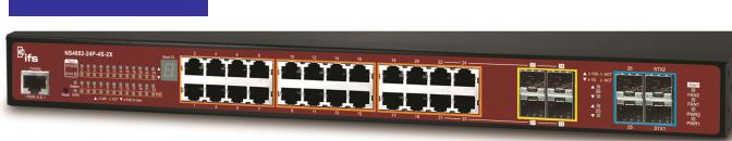
The front panel provides a simple interface monitoring the Managed Switch. Figure 2-1-1 shows the front panel of the Managed Switch.
NS4802-24P-4S-2X Front Panel
Figure 2-1-1: Front Panel of NS4802
■Gigabit TP interface
10/100/1000BASE-T Copper, RJ45 twisted-pair: Up to 100 meters.
■SFP slot
100/1000BASE-X mini-GBIC slot, SFP (Small-form Factor Pluggable) transceiver module: From 550 meters to 2km (multi-mode fiber), up to above 10/20/30/40/50/70/120 kilometers (single-mode fiber).
■10 Gigabit SFP+ slot
10GBASE-SR/LR mini-GBIC slot, SFP+ Transceiver Module supports from 300 meters (multi-mode fiber) to up to 10 kilometers (single-mode fiber)
■10 Gigabit Stacked SFP+ slot
10GBASE-SR/LR mini-GBIC slot, SFP+ Transceiver Module supports from 300 meters (multi-mode fiber) to up to 10 kilometers (single-mode fiber)
■Console Port
The console port is an RJ45 port connector. It is an interface for connecting a terminal directly. Through the console port, it provides rich diagnostic information including IP address setting, factory reset, port management, link status and system setting. Users can use the attached DB9 to RJ45 console cable in the package and connect to the console port on the device. After the connection, users can run any terminal emulation program (Hyper Terminal, ProComm Plus, Telix,
22
Winterm and so on) to enter the startup screen of the device.
■Reset button
At the right of the front panel, the reset button is designed for rebooting the Managed Switch without turning off and on the power. The following is the summary table of reset button functions:
Reset Button Pressed and Released |
Function |
|
|
|
|||
< 5 sec: System Reboot |
Reboot the Managed Switch. |
||
|
|
||
|
Reset the Managed Switch to Factory Default configuration. |
||
|
The Managed Switch will then reboot and load the default |
||
|
settings as shown below: |
||
> 5 sec: Factory Default |
|
Default Username: admin |
|
|
Default Password: admin |
||
|
|||
|
|
Default IP address: 192.168.0.100 |
|
|
|
Subnet mask: 255.255.255.0 |
|
|
|
Default Gateway: 192.168.0.254 |
|
2.1.2 LED Indications
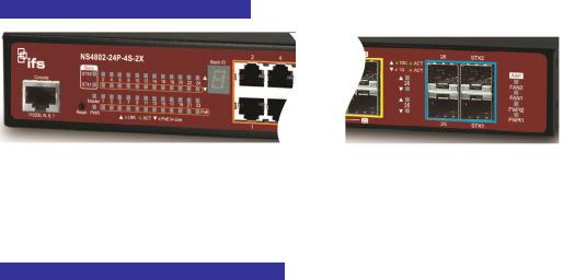
The front panel LEDs indicate instant status of power and system status, fan status, port links / PoE in-use and data activity; they help monitor and troubleshoot when needed. Figure 2-1-2 shows the LED indications of the Managed Switch.
NS4802-24P-4S-2X LED Indication
Figure 2-1-2: Front Panel LEDs of NS4802-24P-4S-2X
NS4802-24P-4S-2X LED Indication Table
LED definition
System / Alert / Stack
LED |
Color |
Function |
|
PWR |
Green |
Lights to indicate that the Switch is powered on. |
|
Blinks to indicate the System is running under booting procedure. |
|||
|
|
||
|
|
|
|
Master |
Green |
Lights to indicate that the Switch is the Master of the stack group. |
|
|
|
|
|
FAN1 |
Green |
Lights to indicate fan1 has failed. |
|
|
|
|
|
FAN2 |
Green |
Lights to indicate fan2 has failed. |
|
|
|
|
|
PWR1 |
Green |
Lights to indicate power supply 1 has failed. |
|
|
|
|
|
PWR2 |
Green |
Lights to indicate power supply 2 has failed. |
|
|
|
|
|
|
|
23 |

|
|
Lights to indicate the link through that SFP+ stacking port is successfully established with |
STX1 |
Green |
speed 10Gbps. |
|
|
Off to indicate that the port is link down. |
|
|
Lights to indicate the link through that SFP+ stacking port is successfully established with |
STX2 |
Green |
speed 10Gbps. |
|
|
Off to indicate that the port is link down. |
Per 10/100/1000BASE-T interfaces (Port-1 to Port-24)
LED |
Color |
Function |
|
|
|
Lights to indicate the link through that port is successfully established at |
|
LNK/ACT |
Green |
10/100/1000Mbps. |
|
|
|
Blinks to indicate that the switch is actively sending or receiving data over that port. |
|
PoE |
Orange |
Lights to Indicate the port is providing 56V DC in-line power. |
|
Blinks to indicate the connected device is not a PoE Powered Device (PD). |
|||
|
|
||
|
|
|
Per 10G uplink SFP+ interface (Port-25 to Port-26)
LED |
Color |
Function |
|
10G |
Green |
Lights to indicate the port is running in 10Gbps speed and successfully established. |
|
LNK/ACT |
Blinks to indicate that the switch is actively sending or receiving data over that port. |
||
|
|||
1G |
Orange |
Lights to indicate the port is running in 1Gbps speed and successfully established. |
|
LNK/ACT |
Blinks to indicate that the switch is actively sending or receiving data over that port. |
||
|
2.1.3 Switch Rear Panel
The rear panel of the Managed Switch indicates an AC inlet power socket, which accepts input power from 100 to 240V AC, 50-60Hz. Figure 2-1-3 shows the rear panel of the Managed Switch.
NS4802-24P-4S-2X Rear Panel
Figure 2-1-3: Rear Panel of NS4802-24P-4S-2X
■AC Power Receptacle
For compatibility with electric service in most areas of the world, the Managed Switch’s power supply automatically adjusts line power in the range of 100-240V AC and 50/60 Hz.
Plug the female end of the power cord firmly into the receptalbe on the rear panel of the Managed Switch and the other end of the power cord into an electric service outlet and the power will be ready.
The device is a power-required device, which means it will not work till it is powered. If your networks should be active all the time, please consider using UPS (Uninterrupted Power Supply) for your device.
Power Notice: It will prevent you from network data loss or network downtime. In some areas, installing a surge suppression device may also help to protect your Managed Switch from being damaged by unregulated surge or current to the Switch or the power adapter.
24
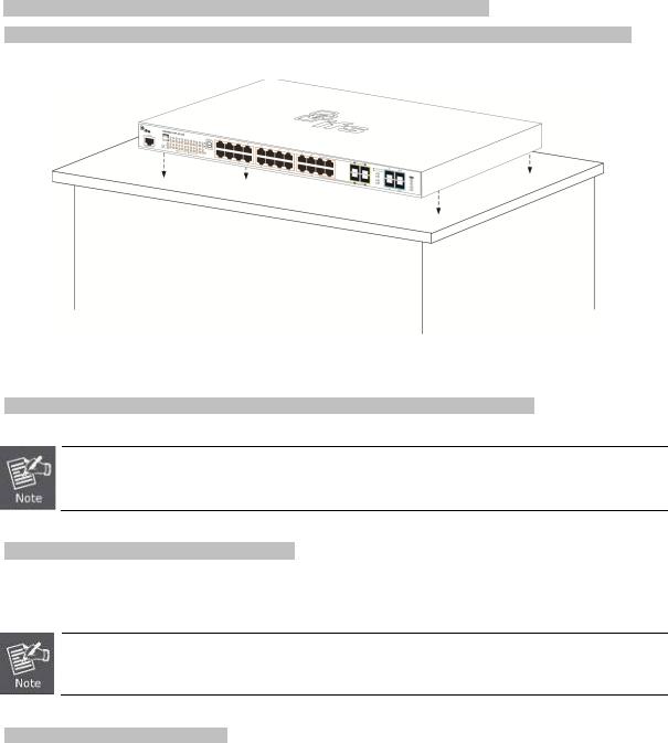
2.2 Installing the Switch
This section describes how to install your Managed Switch and make connections to the Managed Switch. Please read the following topics and perform the procedures in the order being presented. To install your Managed Switch on a desktop or shelf, simply complete the following steps.
2.2.1 Desktop Installation
To install the Managed Switch on desktop or shelf, please follow these steps:
Step 1: Attach the rubber feet to the recessed areas on the bottom of the Managed Switch.
Step 2: Place the Managed Switch on the desktop or the shelf near an AC power source, as shown in Figure 2-2-1.
Figure 2-2-1: Place the Managed Switch on the Desktop
Step 3: Keep enough ventilation space between the Managed Switch and the surrounding objects.
When choosing a location, please keep in mind the environmental restrictions discussed in Chapter 1, Section 4, and specifications.
Step 4: Connect the Managed Switch to network devices.
Connect one end of a standard network cable to the 10/100/1000 RJ-45 ports on the front of the Managed Switch. Connect the other end of the cable to the network devices such as printer server, workstation or router.
Connection to the Managed Switch requires UTP Category 5e network cabling with RJ-45 tips. For more information, please see the Cabling Specification in Appendix A.
Step 5: Supply power to the Managed Switch.
Connect one end of the power cable to the Managed Switch.
Connect the power plug of the power cable to a standard wall outlet.
When the Managed Switch receives power, the Power LED should remain solid Green.
25

2.2.2 Rack Mounting
To install the Managed Switch in a 19-inch standard rack, please follow the instructions described below.
Step 1: Place the Managed Switch on a hard flat surface, with the front panel positioned towards the front side.
Step 2: Attach the rack-mount bracket to each side of the Managed Switch with supplied screws attached to the package. Figure 2-2-2 shows how to attach brackets to one side of the Managed Switch.
Figure 2-2-2: Attach Brackets to the Managed Switch.
You must use the screws supplied with the mounting brackets. Damage caused to the parts by using incorrect screws would invalidate the warranty.
Step 3: Secure the brackets tightly.
Step 4: Follow the same steps to attach the second bracket to the opposite side.
Step 5: After the brackets are attached to the Managed Switch, use suitable screws to securely attach the brackets to the rack, as shown in Figure 2-2-3.
Figure 2-2-3: Mounting Managed Switch in a Rack
Step 6: Proceed with Steps 4 and 5 of session 2.2.1 Desktop Installation to connect the network cabling and supply power to the Managed Switch.
2.2.3 Installing the SFP/SFP+ Transceiver
The sections describe how to insert an SFP/SFP+ transceiver into an SFP/SFP+ slot. The SFP/SFP+ transceivers are hot-pluggable and hot-swappable. You can plug in and out the transceiver to/from any SFP/SFP+ port without having to power down the Managed Switch, as the Figure 2-2-4 shows..
26

Figure 2-2-4: Plug-in the SFP/SFP+ Transceiver
Approved IFS SFP/SFP+ Transceivers
IFS Managed Switch supports both single mode and multi-mode SFP/SFP+ transceiver. The following list of approved IFS SFP/SFP+ transceivers is correct at the time of publication:
Fast Ethernet Transceiver (100Base-X SFP)
Gigabit Ethernet Transceiver (1000BASX-LX-BX, Fiber Bi-Directional SFP)
27
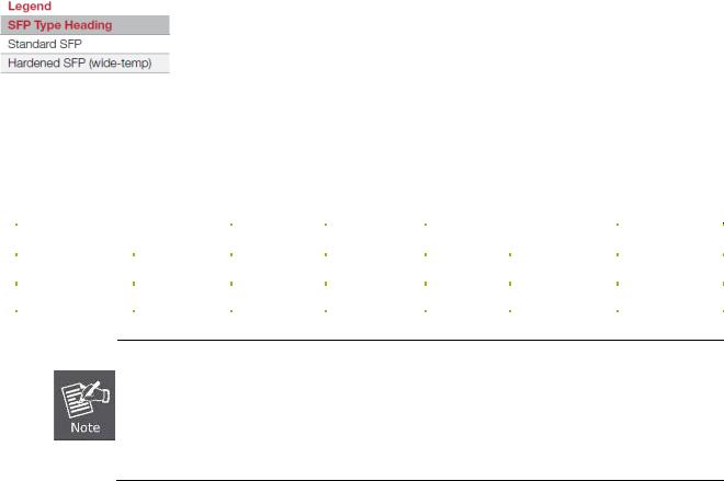
10Gigabit Ethernet Transceiver (10GBASE-X SFP+)
■10 Gigabit Stacked SFP+ slot
10GBASE-SR/LR mini-GBIC slot, SFP+ Transceiver Module supports from 300 meters (multi-mode fiber) to up to 10 kilometers (single-mode fiber)
Model |
Speed (Mbps) |
Connector |
Fiber Mode |
Distance |
Wavelength (nm) |
Operating Temp. |
||
Interface |
||||||||
|
|
|
|
|
|
|
||
S40-2MLC |
10G |
LC |
Multi Mode |
300m |
850nm |
0 ~ 60 |
|
|
|
|
|
|
|
|
|
|
|
S40-2SLC-10 |
10G |
LC |
Single Mode |
10km |
1310nm |
0 ~ 60 |
|
|
|
|
|
|
|
|
|
|
|
1.It is recommended to use IFS SFP on the Managed Switch. If you insert an SFP transceiver that is not supported, the Managed Switch will not recognize it.
2.Port 21 to Port 24 are a shared SFP slot that supports the Gigabit and Fast Ethernet SFP transceiver.
3.Port 25 to Port 26 are a shared SFP+ slot that supports the 10 Gigabit SFP+ transceiver and Gigabit SFP transceiver.
1.Before we connect the NS4802 to the other network device, we have to make sure both sides of the SFP transceivers are with the same media type, for example: 1000BASE-SX to 1000BASE-SX, 1000Bas-LX to 1000BASE-LX.
2.Check whether the fiber-optic cable type matches with the SFP transceiver requirement.
To connect to 1000BASE-SX SFP transceiver, please use the multi-mode fiber cable with one side being the male duplex LC connector type.
To connect to 1000BASE-LX SFP transceiver, please use the single-mode fiber cable with one side being the male duplex LC connector type.
Connect the Fiber Cable
1.Insert the duplex LC connector into the SFP/SFP+ transceiver.
2.Connect the other end of the cable to a device with SFP/SFP+ transceiver installed.
3.Check the LNK/ACT LED of the SFP/SFP+ slot on the front of the Managed Switch. Ensure that the SFP/SFP+ transceiver is operating correctly.
4.Check the Link mode of the SFP/SFP+ port if the link fails. Tofunction with some fiber-NICs or Media Converters, user has to set the port Link mode to “10GForce”, “1000 Force” or “100 Force”.
Remove the Transceiver Module
1.Make sure there is no network activity anymore.
2.Remove the Fiber-Optic Cable gently.
3.Lift up the lever of the SFP module and turn it to a horizontal position.
4.Pull out the module gently through the lever.
28
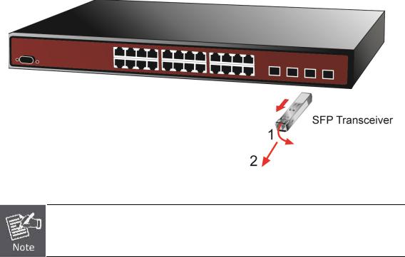
Figure 2-2-5: How to Pull Out the SFP/SFP+ Transceiver
Never pull out the module without lifting up the lever of the module and turning it to a horizontal position. Directly pulling out the module could damage the module and the SFP/SFP+ module slot of the Managed Switch.
2.3 Stack Installation
NS4802-24P-4S-2X
The NS4802 Managed Switch series provides a switch stacking function to manage up to 16 switches using a single IP address. And up to 320 Gigabit Ethernet ports, 64 Gigabit TP/SFP ports and 32 high-capacity 10G SFP+ ports can be managed by a stacking group and you can add ports and functionality as needed. You can add the NS4802 switch as needed to support more network clients, knowing that your switching fabric will scale to meet increasing traffic demands.
Two types of stack topologies are supported by the NS4802.
Chain topology (same as a disconnected ring)
Ring topology
29
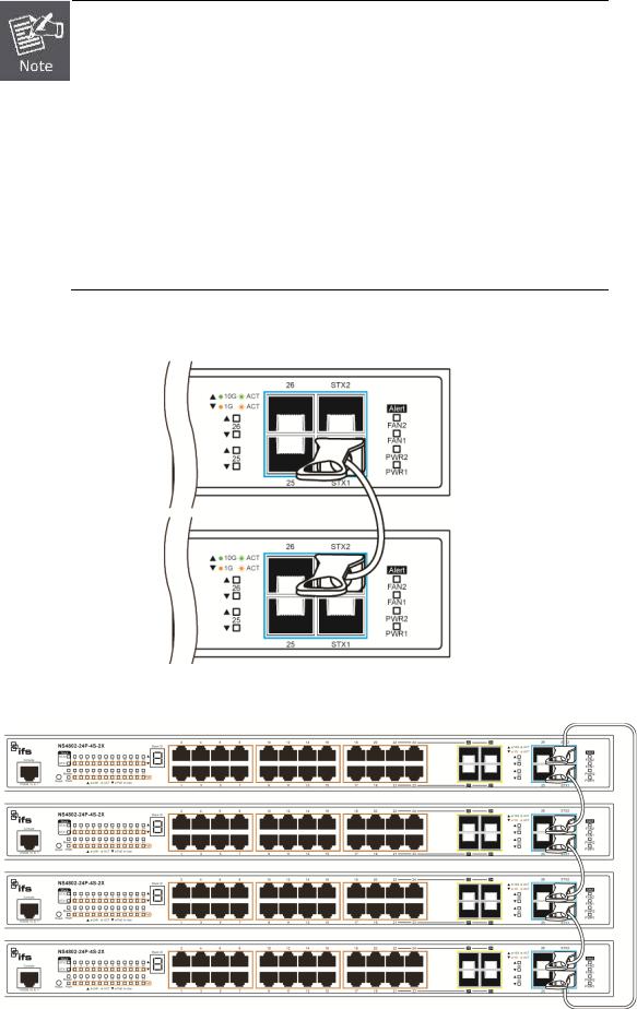
1.Please note that from now on the stacking example images are coming from NS4802, however, as NS4802-24P stacking ports are on the front panel, but the stacking cable connection rule is totally same with NS3601.
2.if you remove one of switch from stacking group and causes stacking ID without sequence, please re-assign stacking ID from “Stack Configuration“before you make the other operation.
3.Stack ports are port27 and port28 and the stacking ports could be used for stacking only, it can’t be set to “uplink”.
Please find the following picture for sample connection.
Figure 2-21 Chain Stack topology
Figure 2-22 Ring Stack topology
30
Loading...