


 Loading...
TruVision IP Camera
Configuration Manual
Firmware 5.0X
P/N 1072665A-EN • REV 1.0 • ISS 25SEP13
Copyright © 2013 UTC Fire & Security Americas Corporation, Inc.
Interlogix is part of UTC Climate Controls & Security, a unit of United Technologies Corporation. All rights reserved.
Trademarks and The TruVision and Interlogix names and logos are trademarks of patents United Technologies.
Other trade names used in this document may be trademarks or registered trademarks of the manufacturers or vendors of the respective products.
Manufacturer UTC Fire & Security Americas Corporation, Inc. 3211 Progress Drive, Lincolntown, NC 28092, USA
Authorized EU manufacturing representative: UTC Fire & Security B.V.
Kelvinstraat 7, 6003 DH Weert, The Netherlands
Contact information For contact information, see www.interlogix.com or www.utcfssecurityproducts.eu.
Customer support www.interlogix.com/customer-support
Content
Chapter 1 |
Introduction |
1 |
|
|
|
|
|
|
Chapter 2 |
Network access |
3 |
|
|
|
|
||
|
Checking your web browser security level 3 |
|||||||
|
Accessing the camera over the internet 5 |
|||||||
|
Overview of the camera web browser |
5 |
||||||
Chapter 3 |
Camera configuration |
9 |
|
|
|
|||
|
Configuration |
9 |
|
|
|
|
|
|
|
Local configuration |
10 |
|
|
|
|
||
|
System time |
12 |
|
|
|
|
|
|
|
Network settings |
13 |
|
|
|
|
||
|
Recording parameters |
17 |
|
|
|
|||
|
Video image |
18 |
|
|
|
|
|
|
|
OSD 21 |
|
|
|
|
|
|
|
|
Overlay text |
22 |
|
|
|
|
|
|
|
Privacy masks 23 |
|
|
|
|
|
||
|
Motion detection alarms |
23 |
|
|
||||
|
Tamper-proof alarms 26 |
|
|
|
||||
|
Exception alarms |
27 |
|
|
|
|
||
|
Alarm inputs and outputs |
27 |
|
|
||||
|
Snapshot parameters 28 |
|
|
|
||||
|
NAS settings |
29 |
|
|
|
|
|
|
|
Storage devices |
30 |
|
|
|
|
||
|
Defining a recording schedule |
30 |
|
|||||
|
Defining RS-232 settings |
32 |
|
|
||||
|
Defining RS-485 settings |
33 |
|
|
||||
Chapter 4 |
Camera management |
35 |
|
|
||||
|
User management |
35 |
|
|
|
|
||
|
Defining RTSP Authentication |
37 |
|
|||||
|
Defining IP Address Filter |
38 |
|
|
||||
|
Defining Telnet |
38 |
|
|
|
|
||
|
Restoring default settings |
38 |
|
|
||||
|
Importing/Exporting Configuration file |
39 |
||||||
|
Upgrading the firmware |
39 |
|
|
||||
|
Rebooting the camera |
40 |
|
|
|
|||
Chapter 5 |
Camera operation |
41 |
|
|
|
|
||
|
Logging on and off |
41 |
|
|
|
|
||
|
Live view mode |
41 |
|
|
|
|
||
|
Playing back recorded video |
42 |
|
|||||
|
Searching event logs 44 |
|
|
|
||||
|
Operating PTZ control |
46 |
|
|
|
|||
TruVision IP Camera Configuration Manual |
|
|
|
|
|
|
i |
|
Index 49
ii |
TruVision IP Camera Configuration Manual |
Chapter 1
Introduction
This is the user manual for TruVision IP camera models:
TVB-1101 (1.3MPX IP bullet camera, PAL)
TVB-3101 (1.3MPX IP bullet camera, NTSC)
TVB-1102 (3MPX IP bullet camera, PAL)
TVB-3102 (3MPX IP bullet camera, NTSC)
TVD-1103 (1.3MPX IP VF mini dome, PAL)
TVD-3103 (1.3MPX IP VF mini dome, NTSC)
TVD-1104 (3MPX IP VF mini dome, PAL)
TVD-3104 (3MPX IP VF mini dome, NTSC)
TVD-1101 (1.3MPX IP indoor mini dome, PAL)
TVD-3101 (1.3MPX IP indoor mini dome, NTSC)
TVD-1102 (3MPX IP indoor mini dome, PAL)
TVD-3102 (3MPX IP indoor mini dome, NTSC)
TVW-1101 (1.3MPX IP wedge dome, PAL)
TVW-3101 (1.3MPX IP wedge dome, NTSC)
TVW-1102 (3MPX IP wedge dome, PAL)
TVW-3102 (3MPX IP wedge dome, NTSC)
TruVision IP Camera Configuration Manual |
1 |
0BChapter 1: Introduction
2 |
TruVision IP Camera Configuration Manual |
Chapter 2
Network access
This manual explains how to configure the camera over the network with a web browser.
TruVision IP cameras can be configured and controlled using Microsoft Internet Explorer (IE) and other browsers. The procedures described use Microsoft Internet Explorer (IE) web browser.
Checking your web browser security level
When using the web browser interface, you can install ActiveX controls to connect and view video using Internet Explorer. However, you cannot download data, such as video and images due to the increased security measure. Consequently you should check the security level of your PC so that you are able to interact with the cameras over the web and, if necessary, modify the Active X settings.
Configuring IE ActiveX controls
You should confirm the ActiveX settings of your web browser.
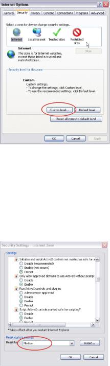
To change the web browser’s security level:
1.In Internet Explorer click Internet Options on the Tools menu.
2.On the Security tab, click the zone to which you want to assign a web site under “Select a web content zone to specify its security settings”.
3.Click Custom Level.
TruVision IP Camera Configuration Manual |
3 |
1BChapter 2: Network access
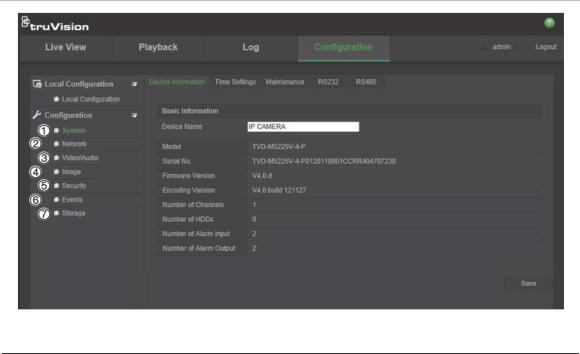
4.Change the ActiveX controls and plug-ins options that are signed or marked as safe to Enable. Change the ActiveX controls and plug-ins options that are unsigned to Prompt or Disable. Click OK.
- or -
Under Reset Custom Settings, click the security level for the whole zone in the Reset To box, and select Medium. Click Reset.
Then click OK to the Internet Options Security tab window.
5. Click Apply in the Internet Options Security tab window.
Windows Vista and 7 users
Internet Explorer for Windows Vista and Windows 7 operating systems have increased security measures to protect your PC from any malicious software being installed.
To have complete functionality of the web browser interface with Windows Vista and Windows 7, do the following:
•Run the Browser interface as an administrator in your workstation
4 |
TruVision IP Camera Configuration Manual |
1BChapter 2: Network access
•Add the camera’s IP address to your browser’s list of trusted sites
To add the camera’s IP address to Internet Explorer’s list of trusted sites:
1.Open Internet Explorer.
2.Click Tools, and then Internet Options.
3.Click the Security tab, and then select the Trusted sites icon.
4.Click the Sites button.
5.Clear the “Require server verification (https:) for all sites in this zone box.
6.Enter the IP address in the “Add this website to the zone” field.
7.Click Add, and then click Close.
8.Click OK in the Internet Options dialog window.
9.Connect to the camera for full browser functionality.
Accessing the camera over the internet
Use the web browser to access and configure the camera over the internet.
It is recommended that you change the administrator password once the set up is complete. Only authorized users should be able to modify camera settings. See “User management” on page 35 for further information.
To access the camera online:
1.In the web browser enter the camera’s IP address (default is 192.168.1.70). Use the tool, TruVision Device Finder, enclosed on the CD to find the IP address of the camera.
The Login dialog box appears.
Note: Ensure that the Active X controls are enabled.
2.Enter your user name and password.
User name: admin Password: 1234
3.Click Login. The web browser window appears in live view mode.
Overview of the camera web browser
The camera web browser lets you view, record, and play back recorded videos as well as manage the camera from any PC with Internet access. The browser’s easy-to-use controls give you quick access to all camera functions. See Figure 1 on page 6.
TruVision IP Camera Configuration Manual |
5 |

1BChapter 2: Network access
If there is more than one camera connected over the network, open a separate web browser window for each individual camera.
Figure 1: Web browser interface
Table 1: Overview of the web browser interface
No. |
Name |
Description |
|
|
|
1. |
Live view |
Click to view live video. |
|
|
|
2. |
Playback |
Click to play back video. |
|
|
|
3. |
Log |
Click to search for event logs. There are three main types: Alarm, |
|
|
Exception and Operation. |
|
|
|
4. |
Configuration |
Click to display the configuration window for setting up the |
|
|
camera. |
|
|
|
5. |
Current user |
Displays current user logged on. |
|
|
|
6. |
Logout |
Click to log out from the system. This can be done at anytime. |
|
|
|
7. |
PTZ controls |
Direction actions, zoom, focus, iris, light and wiper control. |
|
|
Note: Direction actions, lighter and wiper control can be used if |
|
|
the camera supports RS-485 and external pan/tilt unit, light or |
|
|
wiper is installed. |
|
|
|
8. |
Viewer |
View live video. Time, date and camera name are displayed here. |
|
|
|
9. |
Start/stop live view |
Click to start/stop live view. |
|
|
|
10. |
Capture |
Click to take a snapshot of the video. The snapshot will be saved |
|
|
to the default folder in JPEG format. |
|
|
|
11. |
Start/stop recording |
Click to record live video. |
|
|
|
6 |
TruVision IP Camera Configuration Manual |
1BChapter 2: Network access
No. |
Name |
Description |
|
|
|
12. |
Digital Zoom |
Click to enable digital zoom. |
|
|
|
13. |
Bidirectional audio |
Turn on/off microphone. |
|
|
|
14. |
Audio |
Adjust volume. |
|
|
|
TruVision IP Camera Configuration Manual |
7 |
1BChapter 2: Network access
8 |
TruVision IP Camera Configuration Manual |
Chapter 3
Camera configuration
This chapter explains how to configure the cameras through a web browser.
Once the camera hardware has been installed, configure the camera’s settings through the web browser. You must have administrator rights in order to configure the cameras over the internet.
The camera web browser lets you configure the camera remotely using your PC. Web browser options may vary depending on camera model. The camera is configured using on-screen display (OSD) menus.
There are two main folders in the configuration panel:
Local configuration
Configuration
Configuration menu overview
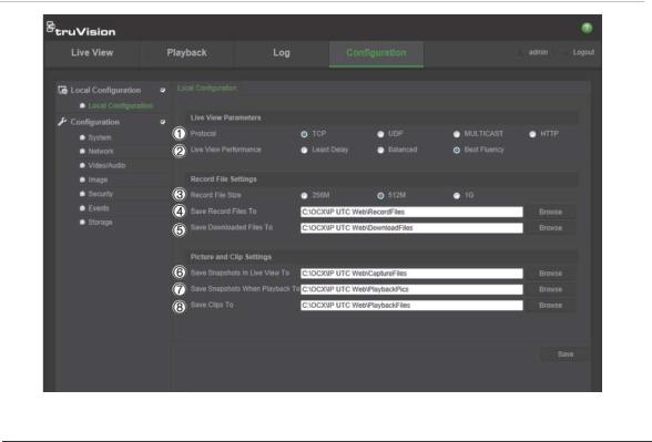
Use the Configuration panel to configure the server, network, camera, alarms, users, transactions and other parameters such as upgrading the firmware. See Figure 2 and Table 2 below for descriptions of the configuration folders available.
TruVision IP Camera Configuration Manual |
9 |
2BChapter 3: Camera configuration
Figure 2: Configuration panel (Device Information tab selected)
Table 2: Overview of the Configuration panel
No. |
Configuration |
Description |
|
folders |
|
1. |
System |
Defines device basic information including SN and the current firmware |
|
|
version, time settings, maintenance, and serial port parameters. |
|
|
|
2. |
Network |
Defines the network parameters required to access the camera over |
|
|
the internet. |
|
|
|
3. |
Video/Audio |
Defines recording parameters. |
|
|
|
4. |
Image |
Defines the image parameters, OSD settings, overlay text, and privacy |
|
|
mask. |
|
|
|
5. |
Security |
Defines who can use the camera, their passwords and access |
|
|
privileges, RTSP authentication, IP address filter, and telnet access. |
|
|
|
6. |
Events |
Defines motion detection, tamper-proof, alarm input/output, exception, |
|
|
and snapshot configuration. |
|
|
|
7. |
Storage |
Defines recording schedule, storage management, and NAS |
|
|
configuration. |
|
|
|
Local configuration
Use the Local menu to manage the protocol type, live view performance and local storage paths. In the Configuration panel, click Local Configuration to display the local configuration window. See Figure 3 and Table 3 below for descriptions of the different menu parameters.
10 |
TruVision IP Camera Configuration Manual |
2BChapter 3: Camera configuration
Figure 3: Example of a configuration window (Local configuration shown)
Table 3: Overview of the Local configuration window
No. |
Parameters |
Description |
|
|
|
|
Live View Parameters |
|
|
|
|
1. |
Protocol |
Specifies the network protocol used. |
|
|
Options include: TCP, UDP, MULTICAST and HTTP. |
|
|
|
2. |
Live View Performance |
Specifies the transmission speed. |
|
|
Options include: Least Delay, Balanced or Best Fluency. |
|
|
|
|
Record File Settings |
|
|
|
|
3. |
Record File Size |
Specifies the maximum file size. |
|
|
Options include: 256 MB, 512 MB and 1G. |
|
|
|
4. |
Save Record Files to |
Specifies the directory for recorded files. |
|
|
|
5. |
Save Downloaded Files to |
Specifies the directory for downloaded files. |
|
|
|
|
Picture and Clip Settings |
|
|
|
|
6. |
Save Snapshots In Live |
Specifies the directory for saving snapshots in live view mode. |
|
View To |
|
|
|
|
7. |
Save Snapshots When |
Specifies the directory for saving snapshots in playback mode. |
|
Playback To |
|
|
|
|
8. |
Save Clips To |
Specifies the directory for saving video clips in playback mode. |
|
|
|
TruVision IP Camera Configuration Manual |
11 |
2BChapter 3: Camera configuration
System time
NTP (Network Time Protocol) is a protocol for synchronizing the clocks of network devices, such as IP cameras and computers. Connecting network devices to a dedicated NTP time server ensures that they are all synchronized.
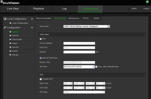
To define the system time and date:
1. In the System folder, click the Time Settings tab to open its window.
2.From the Time Zone drop-down menu, select the time zone that is the closest to the camera’s location.
3.Under Time Sync, check one of the options for setting the time and date:
Synchronize with an NTP server: Check the NTP enable box and enter the server NTP address. The time interval can be set from 1 to 10080 minutes. - Or -
Set manually: Enable the Manual Time Sync function and then click  to set the system time from the pop-up calendar.
Note: You can also check the Sync with computer time checkbox to synchronize the time of the camera with the time of your computer.
4.Check Enable DST to enable the DST function, and set the date of the DST period.
5.Click Save to save changes.
12 |
TruVision IP Camera Configuration Manual |
2BChapter 3: Camera configuration
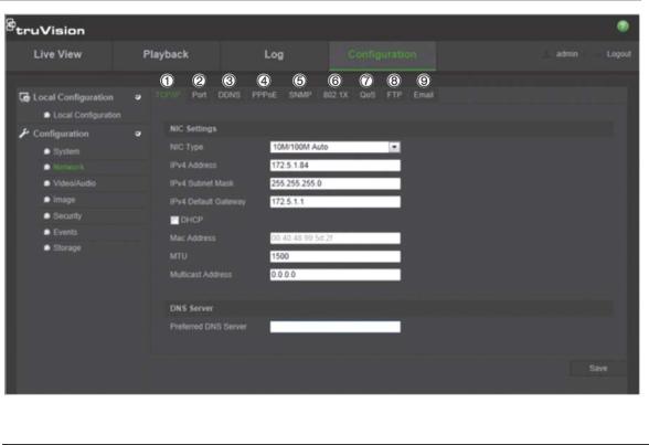
Network settings
Accessing the camera through a network requires that you define certain network settings. Use the “Network” folder to define the network settings. See Figure 4 and Table 4 below for further information.
Figure 4: Network window (TCP/IP tab shown)
Table 4: Network parameters
No. |
Parameters |
Description |
|
|
|
1. |
TCP/IP |
NIC Type: Specifies the NIC type. Default is Auto. Other options include: |
|
|
10M Half-dup, 10M Full-dup, 100M Half-dup and 100M Full-dup. |
|
|
DHCP: Enable to automatically obtain an IP address and other network |
|
|
settings from that server. |
|
|
IPv4 Address: Specifies the IPv4 address of the camera. |
|
|
IPv4 Subnet Mask: Specifies the IPv4 subnet mask. |
|
|
IPv4 Default Gateway: Specifies the IPv4 gateway IP address. |
|
|
IPv6 Mode: Specifies the IPv6 mode, including Manual, DHCP and |
|
|
Router Advertisement. |
|
|
IPv6 Address: Specifies the IPv6 address of the camera. |
|
|
IPv6 Subnet Prefix Length: Specifies the IPv6 prefix length. |
|
|
IPv6 Default Gateway: Specifies the IPv6 gateway IP address. |
|
|
Mac Address: Set to 00:4d:c1:33:11:d4. |
|
|
MTU: Specifies the valid value range of MTU. Default is 1500. |
|
|
Multicast Address: Specifies a D-class IP address between 224.0.0.0 to |
|
|
239.255.255.255. Only specify this option if you are using the multicast |
|
|
function. Some routers prohibit the use of multicast function in case of a |
|
|
network storm. |
|
|
DNS server: Specifies the DNS server for your network. |
|
|
|
TruVision IP Camera Configuration Manual |
13 |
Loading...