


Concord 5” TouchScreen Installation Sheet
Description
Concord 5” TouchScreen, model 60-924-3-C4TS5, features a 5-inch color LCD screen with a graphical user interface designed to control basic functionality of Concord 4, version 4.5 or later.
Multiple touch screens can be added to each Concord panel. An internal speaker provides system status beeps for trouble and alarm indications.
The touch screen provides a convenient option for the following system operations:
•Easily obtain home/building status using At-A-Glance (AAG) sensor status.
•Arm the system (doors, windows, motion sensors, and property).
•Disarm the system.
•Activate a panic alarm to call the central monitoring station in a non-medical emergency.
Equipment
•Alphanumeric keypad (for panel and end user programming)
•4-conductor, 18 to 22-gauge wire
•#6 screws and anchors (included)
•Super bus power supply (optional), PN 600-1019
Tools
•2.5mm flat-blade screwdriver
•#2 Phillips screwdriver
•Drill and drill bits for opening wallboard (3/16and 1/2-inch bits)
Safety information
IMPORTANT SAFETY INFORMATION. READ ENCLOSED WARNINGS AND SAFETY INFORMATION.
 WARNING! Disconnect panel power before servicing.
 CAUTION: Use static electricity precautions when handling electronic components.
Installation guidelines
The touch screen can be the primary interface to the panel or it can act as auxiliary interface working in conjunction with alphanumeric keypads (such as Interlogix P/N 600-1070-E or 60-983).
•The touch screen is not listed to UL Fire Standards and may not be programmed for use with a Fire System in California per CSFM Regulations.
•Mount the touch screen in an environmentally-controlled area (32°F to 120°F/0°C to 49°C).
•Do not exceed the maximum available power given in the panel. Refer to the total system power and guideline section in Concord installation instructions. See Table 1 for touch screen power usage and Table 2 for maximum wire length between touch screen and panel.
•Depending on system loading, multiple touch screens can be installed on a Concord 4 system. See the examples in Table 3 and Table 4.
Table 1: Touch Screen Power Usage
Current (mA) |
Conditions |
|
|
400 |
Maximum alarm current with the buzzer sounding and |
|
the touch screen illuminated from a button press |
|
|
100 |
Typical operation |
|
|
40 |
Power saving mode (no panel AC power) |
|
|
Table 2: Maximum SuperBus Lengths |
|
|
|
Wire gauge |
Max. touch screen wire length between touch |
(shielded or |
screen and panel |
unshielded) |
|
|
|
22 |
120 feet |
|
|
© 2018 UTC Fire & Security Americas Corporation, Inc. |
1 / 8 |
P/N 466-5410 (EN) • REV D • ISS 19MAR18 |
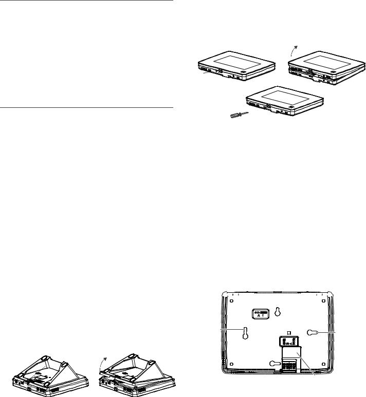
Table 3: Example – Basic Concord 4 system with two Concord 5” TouchScreens and one alphanumeric keypad
Device |
Part # |
Number |
Alarm |
Available |
|
|
used |
current |
Power |
|
|
|
draw |
|
|
|
|
|
|
Concord 4 |
|
|
|
1000 mA |
|
|
|
|
|
Concord 5” |
60-924-3- |
2 |
800 mA |
|
Touch Screen |
C4TS5 |
|
|
|
|
|
|
|
|
ATP 1000 |
60-983 |
1 |
110 mA |
|
|
|
|
|
|
Total |
|
|
|
90 mA |
|
|
|
|
remaining |
|
|
|
|
|
Table 4: Example - Concord 4 system with four Concord 5” TouchScreens, one ADC modem, and one panel voice module (Note: SB 2000 power supply is needed in this configuration)
Device |
Part # |
Number |
Alarm |
Available |
|
|
used |
current |
Power |
|
|
|
draw |
|
|
|
|
|
|
Concord 4 |
|
|
|
1000 mA |
|
|
|
|
|
SB2000 voice |
60-836 |
1 |
600 mA |
|
only module |
|
|
|
|
|
|
|
|
|
Concord 5” |
60-924-3- |
1 |
400 mA |
|
Touch Screen |
C4TS |
|
|
|
|
|
|
|
|
|
|
|
|
0 mA |
|
|
|
|
remaining |
|
|
|
|
|
SB2000 |
600-1019 |
1 |
|
2000 mA |
Power Supply |
|
|
|
|
|
|
|
|
|
ADC LTE |
600-1053- |
1 |
125 mA |
|
Modem |
LTEAT |
|
|
|
|
|
|
|
|
Concord 5” |
60-924-3- |
4 |
1600 mA |
|
Touch Screen |
C4TS5 |
|
|
|
|
|
|
|
|
Total |
|
|
|
875 mA |
|
|
|
|
remaining |
|
|
|
|
|
Preparation
To begin
1.Separate the touch screen and the mounting base from the preassembled desktop stand. Remove the desktop stand by holding the touch screen unit with one hand and prying the desktop stand at the removal tab marking until it separates (Figure 1) with the other.
Figure 1: Desktop stand removal
2 / 8
2.Remove the touch screen from the mounting base pressing the opening button on the bottom of the touch screen (as shown in Figure 2). In case the parts stick to each other, try to separate them by inserting a small screwdriver into the opening slot beneath the protruding opening button (Figure 2).
Figure 2: Opening slot
Opening
button
Wall mounting
1.If the unit is to be installed and used on surface utilizing the desktop stand, skip to step 9.
Wall mounting uses only the mounting base; the desktop stand is not used.
2.Hold the base on the wall at the desired mounting location and mark the mounting holes and bus wire drop.
3.At the mounting hole locations, drill 3/16-inch holes into the wall for plastic anchors.
4.At the bus wire drop opening, drill a 1/2-inch hole into the wall.
5.Push the two plastic anchors into the drilled holes and tighten screws within a quarter-inch of the anchors.
6.Feed the bus wiring through the backside of the bus wire drop in the mounting base (Figures 3 and 4).
Figure 3: Wire access in mounting base
 Mounting


 base
base
Mounting |
Mounting |
|
hole |
||
hole |
||
|
Bus wire drop opening
P/N 466-5410 (EN) • REV D • ISS 19MAR18

Figure 4: Bus Wire Routing Wall Mount
Wires
Terminal
block
7.Hang the base using the screws, level the base, and tighten the screws.
8.Feed any extra bus wire back into wall. Bus wires should not protrude outside of the bus wire drop opening.
Surface, desktop mounting
If the unit is to be wall mounted, skip to step 11.
9.Feed the bus wiring through the desktop stand from the backside forward, and then feed the wire through the backside of the bus wire drop in the mounting base (see Figure 5).
Figure 5: Bus Wire Routing Surface Desktop Mount

 Wires
Wires
10. Reattach the desktop stand to the mounting base.
Wiring and final assembly
11.For either mounting, now connect the bus wires to the 4- position terminal block (Figure 6).
P/N 466-5410 (EN) • REV D • ISS 19MAR18
Figure 6: Connecting the touch screen
GND (Black)
BUS-B (White)
BUS-A (Green)
+12V (Red)
4 |
3 |
2 |
1 |
12.To reattach the touch screen to the mounting base (which is mounted either to a wall or is attached to the desktop stand sitting on a surface), angle the top of the touch screen into the tab hooks on the top of the mounting base and swing the bottom of the touch screen into the lower part of the mounting base until you hear an audible click.
Note: If necessary, use a soft cloth to clear smudges on the touch screen. Do not use glass cleaner.
Power up and bus communication
Follow the steps below for powering up the panel and for verifying that the TouchScreen and other products like an alphanumeric keypad are properly communicating with each other.
Note: On power up, the panel scans the bus for connected devices, assigns a unit number to each bus device, and automatically adds the device ID number of each bus device.
1.Verify that all wiring between the panel, touch screen, and alphanumeric keypad is correct.
2.Connect the panel battery and restore AC power.
The alphanumeric keypad briefly shows SCANNING BUS DEVICES, then displays date and time.
Note: Emergency button program changes can only be completed within two minutes of initial power up of touch screen.
Installer Programming
The Concord 5” TouchScreen has a keypad emulation mode that allows installer/dealer code access to panel programming and configuration.
To access, press the Settings icon  on the Main screen and the Settings screen appears.
3 / 8
 Loading...