


IC-F31GS
INSTRUCTION MANUAL
VHF TRANSCEIVER
iF31GT/GS
UHF TRANSCEIVER
iF41GT/GS

FOREWORD
Thank you for purchasing the IC-F31GT/GS, IC-F41GT/GS FM
transceiver.
READ ALL INSTRUCTIONS carefully and completely before using
the transceiver.
SAVE THIS INSTRUCTION MANUAL–This instruction manual
contains important operating instructions for the transceiver.
ABOUT CE
CE Versions of the IC-F31GT/GS, ICF41GT/GS which display the “CE” symbol on
the serial number seal, comply with the essential requirements of the European Radio
and Telecommunication Terminal Directive
1999/5/EC.
This warning symbol indicates that this equipment operates in nonharmonised frequency bands and/or may be subject to licensing
conditions in the country of use. Be sure to check that you have the
correct version of this radio or the correct programming of this radio,
to comply with national licensing requirements.
INSTALLATION NOTES
• When transmitting with a portable radio, hold the radio in a vertical
position with its microphone 5 to 10 centimeters away from your
mouth. Keep the antenna at least 2.5 centimeters from your head
and body.
• If you wear a portable two-way radio on your body, ensure that the
antenna is at least 2.5 centimeters from your body when transmitting.
i

IMPORTANT
R CAUTION! NEVER hold the transceiver so that the antenna is
very close to, or touching exposed parts of the body, especially the
face or eyes, while transmitting. The transceiver will perform best if
the microphone is 5 to 10 cm away from the lips and the transceiver
is vertical.
R CAUTION! NEVER operate the transceiver with a headset or
other audio accessories at high volume levels.
R CAUTION! NEVER short the terminals of the battery pack.
DO NOT push the PTT when not actually desiring to transmit.
AVOID using or placing the transceiver in direct sunlight or in areas
with temperatures below –10°C or above +50°C.
The basic operations, transmission and reception of the transceiver,
are guaranteed within the specified operating temperature range
(depending on version). However, the LCD display may be operate
correctly, or show an indication in the case of long hours of operation, or after being placed in extremely cold areas.
DO NOT modify the transceiver for any reason.
KEEP the transceiver from the heavy rain, and Never immerse it in
the water. The transceiver construction is water resistant, not waterproof.
The use of non-Icom battery packs/chargers may impair transceiver
performance and invalidate the warranty.
ii

TABLE OF CONTENTS
ABOUT CE . . . . . . . . . . . . . . . . . . . . . . . . . . . . . . . . . . . . . . . . . . . . . .i
INSTALATION NOTES . . . . . . . . . . . . . . . . . . . . . . . . . . . . . . . . . . . . .i
FOREWORD . . . . . . . . . . . . . . . . . . . . . . . . . . . . . . . . . . . . . . . . . . .i–ii
IMPORTANT . . . . . . . . . . . . . . . . . . . . . . . . . . . . . . . . . . . . . . . . . . . .ii
TABLE OF CONTENTS . . . . . . . . . . . . . . . . . . . . . . . . . . . . . . . . . . .iii
1 ACCESSORIES . . . . . . . . . . . . . . . . . . . . . . . . . . . . . . . . . . . . . . . .1
2 PANELDESCRIPTION . . . . . . . . . . . . . . . . . . . . . . . . . . . . . . . .2–4
‘ Switches, controls, keys and connectors . . . . . . . . . . . . . . . . .2–3
‘ Function display . . . . . . . . . . . . . . . . . . . . . . . . . . . . . . . . . . . . . .4
3 BATTERY PACKS . . . . . . . . . . . . . . . . . . . . . . . . . . . . . . . . . . .5–10
‘ Battery pack replacement . . . . . . . . . . . . . . . . . . . . . . . . . . . . . .5
‘ Battery cautions . . . . . . . . . . . . . . . . . . . . . . . . . . . . . . . . . . . . . .6
‘ Battery charging . . . . . . . . . . . . . . . . . . . . . . . . . . . . . . . . . . .7–8
‘ Charging NOTE . . . . . . . . . . . . . . . . . . . . . . . . . . . . . . . . . . . . .9
‘ Battery case (Option) . . . . . . . . . . . . . . . . . . . . . . . . . . . . . . . .10
4 PROGRAMMABLE FUNCTIONS . . . . . . . . . . . . . . . . . . . . . .11–15
‘ General . . . . . . . . . . . . . . . . . . . . . . . . . . . . . . . . . . . . . . . . . . .11
5 CONVENTIONAL OPERATION . . . . . . . . . . . . . . . . . . . . . . . .16–18
‘ Receiving and transmitting . . . . . . . . . . . . . . . . . . . . . . . . . . . .16
‘ Call procedure . . . . . . . . . . . . . . . . . . . . . . . . . . . . . . . . . . . . . .17
‘ Tx code channel selection . . . . . . . . . . . . . . . . . . . . . . . . . . . . .18
‘ Manual 5-tone codes . . . . . . . . . . . . . . . . . . . . . . . . . . . . . . . . .18
‘ Transmitting notes . . . . . . . . . . . . . . . . . . . . . . . . . . . . . . . . . . .18
6 SmarTrunk IITMOPERATION . . . . . . . . . . . . . . . . . . . . . . . . . .19–21
‘ Basic operation . . . . . . . . . . . . . . . . . . . . . . . . . . . . . . . . . . . . .19
7 OTHER FUNCTIONS . . . . . . . . . . . . . . . . . . . . . . . . . . . . . . . . . . .22
‘ DTMF pager/Code squelch . . . . . . . . . . . . . . . . . . . . . . . . . . . .22
8 OPTIONAL UNIT INSTALLATION . . . . . . . . . . . . . . . . . . . . . . . . .23
‘ Installation . . . . . . . . . . . . . . . . . . . . . . . . . . . . . . . . . . . . . . . . .23
9 CLONING . . . . . . . . . . . . . . . . . . . . . . . . . . . . . . . . . . . . . . . . . . . .24
10 OPTIONS . . . . . . . . . . . . . . . . . . . . . . . . . . . . . . . . . . . . . . . .25–26
‘ Options . . . . . . . . . . . . . . . . . . . . . . . . . . . . . . . . . . . . . . . .25–26
11 MEMO . . . . . . . . . . . . . . . . . . . . . . . . . . . . . . . . . . . . . . . . . . . . . .27
iii
ACCESSORIES
q
w
To release the belt clip
To attach the belt clip
‘‘
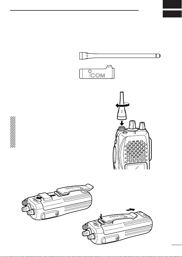
Accessory attachment
D Supplied accessories
The transceiver comes supplied with the following accessories.
q Flexible antenna
differ from that shown,
or may not be supplied
with some versions)
w Belt clip
D Antenna
The antenna screws onto the transceiver
as illustrated at right.
✔
For IC-F31GT-L/GS-L
The most suitable flexible antenna
should be purchased according to programmed frequency parameters. See
page 26 for details.
D Belt clip
Attach the belt clip to the transceiver as illustrated below.
(may
1
1
2
q
w
e
r
t
y
u
i
o
!0
!1
Microphone
Speaker
!2
‘‘
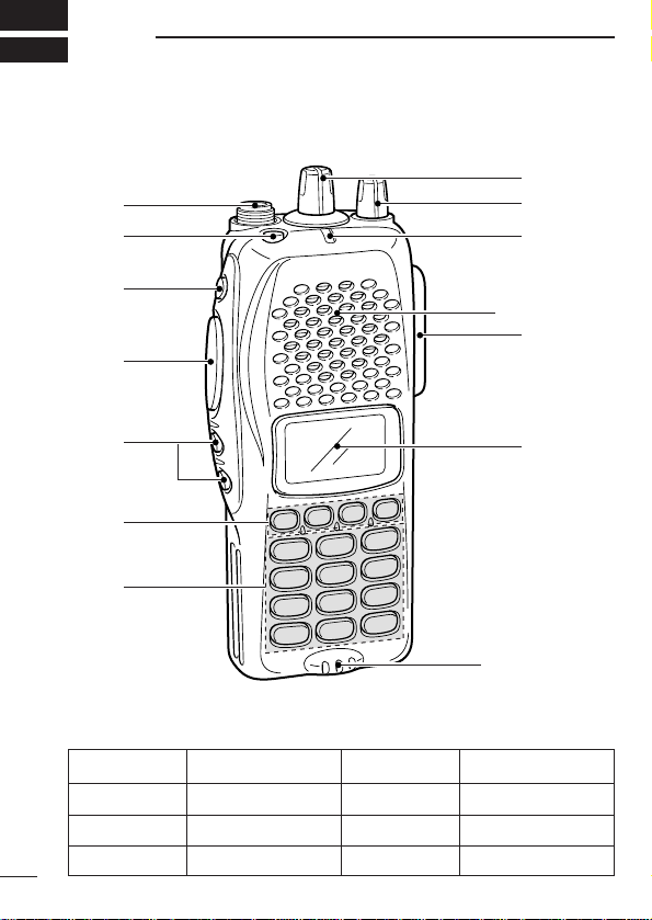
PANEL DESCRIPTION
Switches, controls, keys and connectors
DD
Programmable key reference
F0 (Red)
F1 (Black)
F2 (Black)
F3 (Black)
2
P
P1
P2
P3
0

PANELDESCRIPTION
q ANTENNA CONNECTOR
Connects the supplied antenna.
w DEALER-PROGRAMMABLE KEY [F0 (Red)]
e DEALER-PROGRAMMABLE KEY [F1 (Black)]
r PTT SWITCH [PTT]
Push and hold to transmit; release to receive.
t DEALER-PROGRAMMABLE KEYS [F2 (Black)], [F3 (Black)]
• Push to select the operating channel. Depends on setting.
• Can be programmed as [ ✱ ]/[ # ]. (SmarTrunk mode only)
y DEALER-PROGRAMMABLE KEYS [P
0]/[P1]/[P2]/[P3]
Can each be programmed for one of several functions by your
Icom Dealer.
u 10-KEY PAD (IC-F31GT/IC-F41GT only)
Used to enter DTMF codes, the operating channel, etc.
i FUNCTION DISPLAY
Displays a variety of information, such as, operating channel
number/names, 5-tone code, remaining battery power, DTMF
numbers, transmit output power setting, Audible indication, etc.
NOTE: The above functions depend on pre-setting.
o MULTI CONNECTOR
Connect optional speaker-microphone, etc..
!0 TRANSMIT/BUSY INDICATOR
Lights red while transmitting; lights green while receiving a signal, or when the squelch is open.
!1 VOLUME CONTROL [VOL]
Turns power ON and adjusts the audio level.
!2 ROTARY SELECTOR [SEL]
Selects operating channel, or bank. Depends on setting.
2
3

2
q
w
e
r
t
y
u
i
o
PANELDESCRIPTION
‘‘
Function display
q SIGNAL STRENGTH METER
Indicates relative signal strength level.
w BANK NUMBER INDICATOR
Indicates operating bank (channel group) number.
e LOW POWER INDICATOR
Appears when low output power is selected.
r MULTI-FUNCTION INDICATOR
Indicates operating channel number, channel names, 5-tone
code, etc., according to operating condition.
t SCRAMBLER INDICATOR
Appears while the voice scrambler function is activated.
y KEY LOCK INDICATOR
Appears during key lock function ON.
u BELL INDICATION
Appears or blinks when a 2/5Tone call is received.
i AUDIBLE INDICATOR
Appears when the monitor function is turned ON. (CTCSS and
DTCS mutes are released.)
o BATTERY INDICATOR
Indicates remaining battery power.
4

BATTERY PACKS
‘‘
Battery pack replacement
Before replacing the battery pack, the volume control MUST be ro-
tated fully counterclockwise, until a click is heard, to turn the power
OFF.
• Slide the battery release forward, then pull the battery pack upward with the transceiver facing away from you.
DD
BATTERY PACKS
Charging period
Battery
BP-208
BP-209 7.2 V 1100mAh 15 hrs. 1.5 hrs. 7 hrs.
BP-210 7.2 V 1650 mAh 15 hrs. 2.0 hrs. 11hrs
*1Battery life is calculated under the following conditions;
Tx : Rx : standby =5 : 5 : 90
*2Operating period depends on alkaline cells used.
Voltage Capacity
pack BC-137 BC-121
Battery case for AA
(R6)×6 alkaline
N/A N/A —*
BC-144 or
with AD-94
3
Battery life*
2
1
5

BATTERYPACKS
3
‘‘
Battery cautions
• CAUTION! NEVER short terminals (or charging terminals) of the
battery pack. Also, current may flow into nearby metal objects
such as a necklace, so be careful when placing battery packs (or
the transceiver) in handbags, etc.
Simply carrying with or placing near metal objects such as a necklace, etc. causes shorting. This will damage not only the battery
pack, but also the transceiver.
• NEVER incinerate used battery packs. Internal battery gas may
cause an explosion.
• NEVER immerse the battery pack in water. If the battery pack be-
comes wet, be sure to wipe it dry BEFORE attaching it to the
transceiver.
• Clean the battery terminals to avoid rust or miss contact.
• Keep battery contacts clean. It’s a good idea to clean battery ter-
minals once a week.
If your battery pack seems to have no capacity even after being
charged, completely discharge it by leaving the power ON
overnight. Then, fully charge the battery pack again. If the battery
pack still does not retain a charge (or only very little charge), a new
battery pack must be purchased. (p. 9)
6
 Loading...