


INSTRUCTION MANUAL
PMR446 FM TRANSCEIVER
iF25SR

IMPORTANT
READ ALL INSTRUCTIONS carefully and completely before using the transceiver.
SAVE THIS INSTRUCTION MANUAL— This instruc-
tion manual contains important operating instructions for the IC-
F25SR PMR446 FM TRANSCEIVER.
EXPLICIT DEFINITIONS
WORD |
DEFINITION |
RWARNING
Personal injury, fire hazard or electric shock may occur.
CAUTION Equipment damage may occur.
NOTE
If disregarded, inconvenience only. No risk of personal injury, fire or electric shock.
Icom, Icom Inc. and the 
 logo are registered trademarks of Icom Incorporated (Japan) in the United States, the United Kingdom, Germany, France, Spain, Russia and/or other countries.
All other products or brands are registered trademarks or trademarks of their respective holders.
i

PRECAUTIONS
R CAUTION! NEVER hold the transceiver so that the antenna is very close to, or touching exposed parts of the body, especially the face or eyes, while transmitting. The transceiver will perform best if the microphone is 5 to 10 cm away from the lips and the transceiver is vertical.
R CAUTION! NEVER operate the transceiver with a headset or other audio accessories at high volume levels.
R CAUTION! NEVER short the terminals of the battery pack.
DO NOT push [PTT] when not actually desiring to transmit.
AVOID using or placing the transceiver in direct sunlight or in areas with temperatures below –25°C or above +55°C.
The basic operations, transmission and reception of the transceiver are guaranteed within the specified operating temperature range.
DO NOT modify the transceiver for any reason.
Optional unit installation should be done at an authorized Icom service center only.
KEEP the transceiver from heavy rain, and never immerse it in the water. The transceiver construction is water resistant, not waterproof.
The use of non-Icom battery packs/chargers may impair transceiver performance and invalidate the warranty.
ii

DOC
CE versions of the IC-F25SR which display the “CE” symbol on the serial number seal, comply with the essential requirements of the European Radio and Telecommunication Terminal Directive 1999/5/EC.
|
|
|
|
DECLARATION |
|
|
|
|
|
OF CONFORMITY |
|
||
We Icom Inc. Japan |
0168 |
|
|
|||
Osaka 547-0003, Japan |
|
|
||||
1-1-32, Kamiminami, Hirano-ku |
|
|
|
|||
Declare on our sole responsibility that this equipment complies with the |
|
|
|
|||
essential requirements of the Radio and Telecommunications Terminal |
|
|
|
|||
Equipment Directive, 1999/5/EC, and that any applicable Essential Test |
14th Jul. 2006 |
|
|
|||
Suite measurements have been performed. |
Place and date of issue |
|
||||
Kind of equipment: UHF PMR TRANSCEIVER
Type-designation: iCf25sr
Version (where applicable):
This compliance is based on conformity with the following harmonised standards, specifications or documents:
i)EN 60950-1 2001
ii)EN 300 296-2 (March 2001)
iii)EN 301 489-1 V1.4.1 (August 2002)
iv)EN 301 489-5 V1.3.1 (August 2002)
Authorized representative name
H. Ikegami
General Manager
Signature
iii

TABLE OF CONTENTS
IMPORTANT …………………………………………………………………… i EXPLICIT DEFINITIONS ……………………………………………………… i PRECAUTIONS ………………………………………………………………… ii DOC……………………………………………………………………………… iii TABLE OF CONTENTS ……………………………………………………… iv
1ACCESSORIES ………………………………………………………… 1–4
‘Supplied accessories …………………………………………………… 1
‘Accessory attachments ………………………………………………… 2
2PANEL DESCRIPTION ………………………………………………… 5–8
‘Front, top and side panels ……………………………………………… 5
‘LED indicator …………………………………………………………… 7
‘Programmable function keys …………………………………………… 8
3BASIC OPERATION ………………………………………………… 9–17
‘Receiving and transmitting …………………………………………… 9
‘Setting the squelch level ……………………………………………… 11
‘Auto scan function …………………………………………………… 11
‘Battery type selection ………………………………………………… 12
‘Setting the group code number ……………………………………… 13
‘Find scan operation …………………………………………………… 17
4RINGER FUNCTION ………………………………………………… 18–20
‘Call-Ring operation …………………………………………………… 18
‘Smart-Ring operation ………………………………………………… 19
5OTHER FUNCTIONS………………………………………………… 21–23
‘Monitor audible function ……………………………………………… 21
‘Time-Out Timer ………………………………………………………… 21
‘Power save function …………………………………………………… 22
‘Low battery indication ………………………………………………… 22
‘Scrambler function……………………………………………………… 23
‘All reset function ……………………………………………………… 23
6BATTERY CHARGING ……………………………………………… 24–32
‘Caution ………………………………………………………………… 24
‘Battery chargers………………………………………………………… 27
7BATTERY CASE……………………………………………………… 33–34
‘Optional battery case (BP-240) ……………………………………… 33
8SWIVEL BELT CLIP ………………………………………………… 35–38
‘MB-93 contents ………………………………………………………… 35
‘Attaching ………………………………………………………………… 35
‘Detaching ……………………………………………………………… 37
9OPTIONS ……………………………………………………………… 39–40
10SPECIFICATIONS …………………………………………………… 41–42
iv

1 ACCESSORIES
■ Supplied accessories
Battery pack |
Battery charger |
Belt clip |
Jack cover |
AC adapter*1 |
|
(with screws) |
(for the battery charger) |
Unit cover*2 (double-sided tape)
*1 Depends on version.
*2 Use the unit cover as a spare. Ask your dealer for details.
1
ACCESSORIES 1
■ Accessory attachments |
1 |
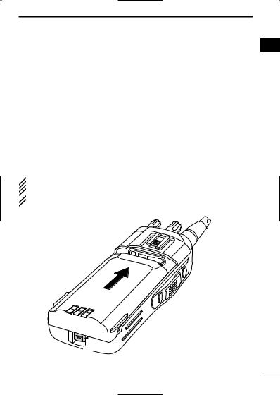
ï Battery pack
To attach the battery pack:
Slide the battery pack in the direction of the arrow (q), then lock it with the battery release button.
•Slide the battery pack until the battery release button makes a ‘click’ sound.
To release the battery pack:
Push the battery release button in the direction of the arrow (w). Then slide the battery pack in the direction opposite to the arrow (q).
 NEVER release or attach the battery pack when the transceiver
is wet or soiled. This may result in water or dust getting into the
 transceiver/battery pack and may result in the transceiver being
  damaged.
q |

 Battery release button
  w
w
2

1 ACCESSORIES
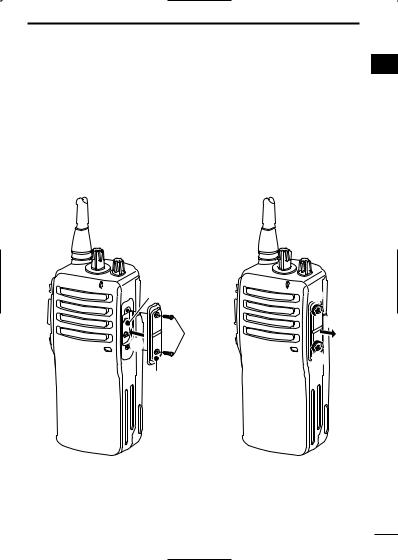
D Belt clip
To attach the belt clip:
q Release the battery pack if it is attached.
wSlide the belt clip in the direction of the arrow until the belt clip is locked and makes a ‘click’ sound.
To detach the belt clip:
q Release the battery pack if it is attached.
wPinch to lift the clip (q), and slide the belt clip in the direction of arrow (w).
w
q
3
ACCESSORIES |
1 |
ï Jack cover |
1 |
Attach the jack cover when the optional speaker-microphone or headset is not used.
To attach the jack cover:
q Attach the jack cover to the [MIC/SP] jack.
w Tighten the screws using a Phillips screwdriver.
To detach the jack cover:
q Unscrew the screws using a Phillips screwdriver.
w Detach the jack cover for the optional speaker-microphone or headset connection.
[MIC/SP] jack |
q |
|
w |
w |
|
q |
|
|
q |
Jack cover |
|
 CAUTION!: Use the supplied screws only.
4

2 PANEL DESCRIPTION
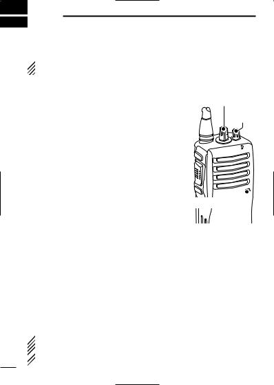
■ Front, top and side panels
|
q |
Antenna |
w |
|
|
|
e |
u
|
Speaker |
y |
r |
t |
Microphone |
q CHANNEL SELECTOR [CH selector]
Rotate to select the pre-programmed memory channels.
w VOLUME CONTROL [VOL]
Rotate to turn the power ON/OFF and adjust the audio level.
5
PANEL DESCRIPTION |
2 |
e LED INDICATOR (p. 7) |
2 |
Lights red while transmitting.
Lights green while receiving a signal, or when the squelch is open.
Blinks orange after transmitting/receiving a Smart-Ring call.
Blinks green to indicate the low battery condition.
r EXTERNAL MICROPHONE/SPEAKER JACK [MIC/SP]
Connect an optional speaker-microphone or headset.
Jack cover
NOTE: Attach the jack cover when optional equipment is not used.
See page 4 for details.
t PROGRAMMABLE KEY [Lower]
The desired function can be assigned. (p. 8)
y PTT SWITCH [PTT]
Push and hold to transmit; release to receive.
u PROGRAMMABLE KEY [Upper]
The desired function can be assigned. (p. 8)
6

2 PANEL DESCRIPTION
‘ LED indicator
The LED indicator indicates the information as follows;
(Ref.; R=Red, G=Green, O=Orange)
• TX: Turns Red while transmitting a signal.
R ( O ) *
• RX: Turns Green while receiving a signal.
G
• Call LED (Blink): Transmitting or receiving the Smart-Ring.
O 
 O
O
• Auto/Find scan: Blinks while Auto/Find scan is activated.
G |
G |
• Low BATT1: You should charge the battery. (blinks slowly)
G 
 G
G
• Low BATT2: You must charge the battery. (blinks fast)
G G |
G G |
• TX low BATT1: Low BATT1 was detected during TX mode.
R |
R |
• TX low BATT2: Low BATT2 was detected during TX mode.
R |
R |
R |
R |
* During the alkaline battery operation.
7

PANEL DESCRIPTION 2
‘ Programmable function keys
The desired key function can be assigned to [Upper] and [Lower] 2 in following way.
q Turn power OFF in advance.
w Rotate [CH selector] to select channel 16.
eRotate [VOL] to turn power ON while pushing and holding the desired key, [Upper] or [Lower], to be assigned.
• The beep is emitted depending on the selected function as below.
[Smart Ring/Ringer] |
1 high beep is emitted. |
[Moni] |
2 high beeps are emitted. |
[Scrambler] |
3 high beeps are emitted. |
[Null] |
1 high beep is emitted for 1 sec. |
|
|
r Turn power OFF.
t Repeat steps e and r until the desired key function is assigned.
NULL KEY
No function.
SMART RING/RINGER KEY
Push to send a Smart-Ring call.
Push and hold for 1 sec. to send a Call-Ring.
MONITOR KEY
Push to mute the CTCSS (or DTCS) squelch mute.
Push and hold for 1 sec. to release the CTCSS (or DTCS) squelch mute.
Open any squelch/deactivate any mute while pushing and holding this key.
VOICE SCRAMBLER FUNCTION KEY
Push to turn the voice scrambler function OFF.
Push and hold for 1 sec. to turn the voice scrambler function ON.
8
3 BASIC OPERATION
■ Receiving and transmitting
 Prior to using the transceiver for the first time, the battery pack must be fully charged for optimum life and operation. (P. 24)
Receiving:
q Rotate [VOL] clockwise to turn power ON.
wRotate [CH selector] to select the desired operating channel.
•Set your group code number if required. (pgs. 13–16)
•Scan starts automatically when channel 16 is selected. (p. 11)
eListen for a transmission and adjust [VOL] to a comfortable listening level.
•The LED indicator turns green, when the received signal contains the same CTCSS tone or DTCS code.
•When no transmission is heard, push and hold [MONI] while adjusting [VOL].
[CH selector]
[VOL]
Microphone
rThe transceiver is now set to receive desired calls on the selected channel.
Transmitting:
Wait for the channel to become clear to avoid interference.
q While pushing and holding [PTT], speak into the microphone at a normal voice level.
• The LED indicator turns red.
w Release [PTT] to return to receive.
 IMPORTANT!: To maximize the readability of your signal;
1. Pause briefly after pushing [PTT].
 2. Hold the microphone 5 to 10 cm from your lips, then speak
  into the microphone at a normal voice level.
9

BASIC OPERATION 3
D Frequency channel/CTCSS tone list (default)
CH |
Frequency (MHz)*1 |
Tone (Hz)*2 |
|
3 |
1 |
446.006250 |
No setting |
|
|
2 |
446.018750 |
No setting |
|
|
3 |
446.031250 |
No setting |
|
|
4 |
446.043750 |
107.2 |
|
|
5 |
446.056250 |
110.9 |
|
|
6 |
446.068750 |
114.8 |
|
|
7 |
446.081250 |
118.8 |
|
|
8 |
446.093750 |
123.0 |
|
|
9 |
446.006250 |
127.3 |
|
|
10 |
446.018750 |
131.8 |
|
|
11 |
446.031250 |
136.5 |
|
|
12 |
446.043750 |
141.3 |
|
|
13 |
446.056250 |
146.2 |
|
|
14 |
446.068750 |
151.4 |
|
|
15 |
446.081250 |
156.7 |
|
|
16 |
Auto Scan |
— |
|
|
|
|
|
|
|
*1 All operating channel frequencies cannot be changed.
*2 CTCSS tones can be programmed. You can use DTCS (Digital Tone Code Squelch) instead of CTCSS. (p. 15)
10
 Loading...