


IC-M502
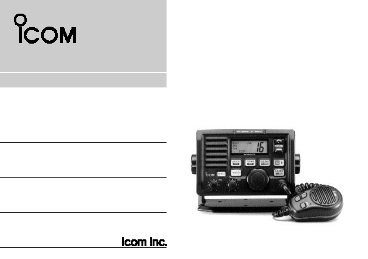
INSTRUCTION MANUAL
VHF MARINE TRANSCEIVER
iM502
This device complies with Part 15 of the FCC rules. Operation is subject to the following two conditions: (1) This device may not cause
harmful interference, and (2) this device must accept any interference
received, including interference that may cause undesired operation.

IMPORTANT
READ ALL INSTRUCTIONS carefully and completely
before using the transceiver.
IN CASE OF EMERGENCY
If your vessel requires assistance, contact other vessels and
the Coast Guard by sending a distress call on channel 16.
USING CHANNEL 16
DISTRESS CALL PROCEDURE
1. “MAYDAY MAYDAY MAYDAY.”
2. “THIS IS ...............” (name of vessel)
3. Your call sign or other indication of the vessel
(AND 9-digit DSC ID if you have one).
4. “LOCATED AT ...............” (your position)
5. The kind of the distress and assistance
required.
6. Any other information which might facilitate
the rescue.
SAVE THIS INSTRUCTION MANUAL — This in-
struction manual contains important operating instructions for
the IC-M502.
Or, transmit your distress call using digital selective calling on
channel 70.
USING DIGITAL SELECTIVE CALLING
(Ch 70)
DISTRESS CALL PROCEDURE
1. While lifting up the switch cover, push and
hold [DISTRESS] for 5 sec. until you hear 5
short beeps change to one long beep.
2. Wait for an acknowledgment from a coast
station.
• Channel 16 is automatically selected.
3. Push and hold [PTT], then transmit the
appropriate information as at left.
i

TABLE OF CONTENTS
IMPORTANT .............................................. i
IN CASE OF EMERGENCY ...................... i
TABLE OF CONTENTS ............................ ii
CAUTIONS ............................................... iii
1 OPERATING RULES .................. 1
2 PANEL DESCRIPTION .......... 2– 5
■ Panel description ............................ 2
■ Function display .............................. 4
■ Microphone ..................................... 5
3 BASIC OPERATION ............ 6 – 10
■ Channel selection ........................... 6
■ Microphone lock function ................ 7
■ Receiving and transmitting ............. 8
■ Call channel programming .............. 9
■ Channel names .............................. 9
■ Optional voice scrambler
operation ....................................... 10
4 DUALWATCH/TRI-WATCH ....... 11
■ Description .................................... 11
■ Operation ...................................... 11
5 SCAN OPERATIONS ......... 12 – 13
■ Scan types .................................... 12
■ Setting tag channels ..................... 13
■ Starting a scan .............................. 13
6 DSC OPERATION .............. 14 – 28
■ MMSI code programming ............. 14
■ Position and time programming .... 14
■ Position indication ......................... 15
■ Distress call .................................. 16
■ Transmitting DSC calls ................. 17
■ Setting the distress information .... 21
■ DSC individual ID ......................... 22
■ Receiving DSC calls ..................... 23
■ DSC set mode .............................. 26
■ Receive messages ....................... 28
7 INTERCOM OPERATION ......... 29
■ Intercom operation ........................ 29
8 SET MODE ........................ 30– 33
■ Set mode programming ................ 30
■ Set mode items ............................. 31
9 CONNECTIONS AND
MAINTENANCE ................. 34– 39
■ Supplied accessories .................... 34
■ Antenna ........................................ 34
■ Fuse replacement ......................... 34
■ Cleaning ....................................... 34
■ Connections .................................. 35
■ Mounting the transceiver .............. 36
■ Optional unit installation ............... 38
■ Dimensions.................................... 39
10 TROUBLESHOOTING .............. 40
11 CHANNEL LIST ........................ 41
12 SPECIFICATIONS AND
OPTIONS ........................... 42 – 43
■ Specifications ............................... 42
■ Options ......................................... 43
13 HM-127 REMOTE-CONTROL
MICROPHONE ................... 44 – 56
■ Panel description .......................... 44
■ Function display ............................ 46
■ HM-127 supplied accessories ...... 47
■ Installation .................................... 48
■ Channel selection ......................... 50
■ Receiving and transmitting ........... 51
■ RF attenuator function .................. 51
■ Lock functions ............................... 52
■ Display backlighting ...................... 52
■ Monitor function ............................ 52
■ Call channel programming ............ 53
■ Optional voice scrambler
operation ....................................... 53
■ Starting a scan .............................. 54
■ Setting tag channels ..................... 54
■ Dualwatch/Tri-watch operation ..... 54
■ Set mode programming ................ 55
■ Intercom operation ........................ 56
■ Channel names ............................ 56
TEMPLATE
ii

CAUTIONS
RWARNING! NEVER connect the transceiver to an AC
outlet. This may pose a fire hazard or result in an electric
shock.
CAUTION: Changes or modifications to this device, not ex-
pressly approved by Icom Inc., could void your authority to
operate this device under FCC regulations.
NEVER connect the transceiver to a power source of more
than 16 V DC or use reverse polarity. This will ruin the transceiver.
NEVER cut the DC power cable between the DC plug and
fuse holder. If an incorrect connection is made after cutting,
the transceiver may be damaged.
NEVER place the transceiver where normal operation of the
vehicle may be hindered or where it could cause bodily injury.
KEEP the transceiver at least 3.3 ft (1 m) away from the
ship’s navigation compass.
DO NOT use or place the transceiver in areas with temper-
atures below –4°F (–20°C) or above +140°F (+60°C) or, in
areas subject to direct sunlight, such as the dashboard.
AVOID the use of chemical agents such as benzine or al-
cohol when cleaning, as they may damage the transceiver
surfaces.
BE CAREFUL! The transceiver rear panel will become
hot when operating continuously for long periods.
Place the transceiver in a secure place to avoid inadvertent
use by children.
BE CAREFUL! The transceiver and optional HM-127 em-
ploy waterproof construction, which corresponds to JIS waterproof specification, grade 7 (1 m/30 min.). However, once
the transceiver or microphone has been dropped, waterproofing cannot be guaranteed due to the fact that the case
may be cracked, or the waterproof seal damaged, etc.
CLEAN THE TRANSCEIVER AND MICROPHONE
THOROUGHLY WITH FRESH WATER after exposure to
water including fresh water, otherwise, the keys and
iii

OPERATING RULES
1
PRIORITIES
•Read all rules and regulations pertaining to priorities and
keep an up-to-date copy handy. Safety and distress calls
take priority over all others.
• You must monitor channel 16 when you are not operating on
another channel.
•False or fraudulent distress signals are prohibited and punishable by law.
PRIVACY
•Information overheard but not intended for you cannot lawfully be used in any way.
• Indecent or profane language is prohibited.
RADIO LICENSES
(1) SHIP STATION LICENSE
You must have a current radio station license before using the
transceiver. It is unlawful to operate a ship station which is not
licensed.
Inquire through your dealer or the appropriate government
agency for a Ship-Radiotelephone license application. This
government-issued license states the call sign which is your
craft’s identification for radio purposes.
(2) OPERATOR’S LICENSE
A Restricted Radiotelephone Operator Permit is the license
most often held by small vessel radio operators when a radio
is not required for safety purposes.
The Restricted Radiotelephone Operator Permit must be
posted or kept with the operator. Only a licensed radio operator may operate a transceiver.
However, non-licensed individuals may talk over a transceiver
if a licensed operator starts, supervises, ends the call and
makes the necessary log entries.
Keep a copy of the current government rules and regulations
handy.
Radio license for boaters (U.S.A. only)
The Telecommunications Act of 1996 permits recreational
boaters to have and use a VHF marine radio, EPIRB, and
marine radar without having an FCC ship station license.
Boaters traveling on international voyages, having an HF
single sideband radiotelephone or marine satellite terminal,
or required to carry a marine radio under any other regulation must still carry an FCC ship station license. For further
information, see the FCC Ship Radio Stations Fact Sheet.
1
2
PANEL DESCRIPTION
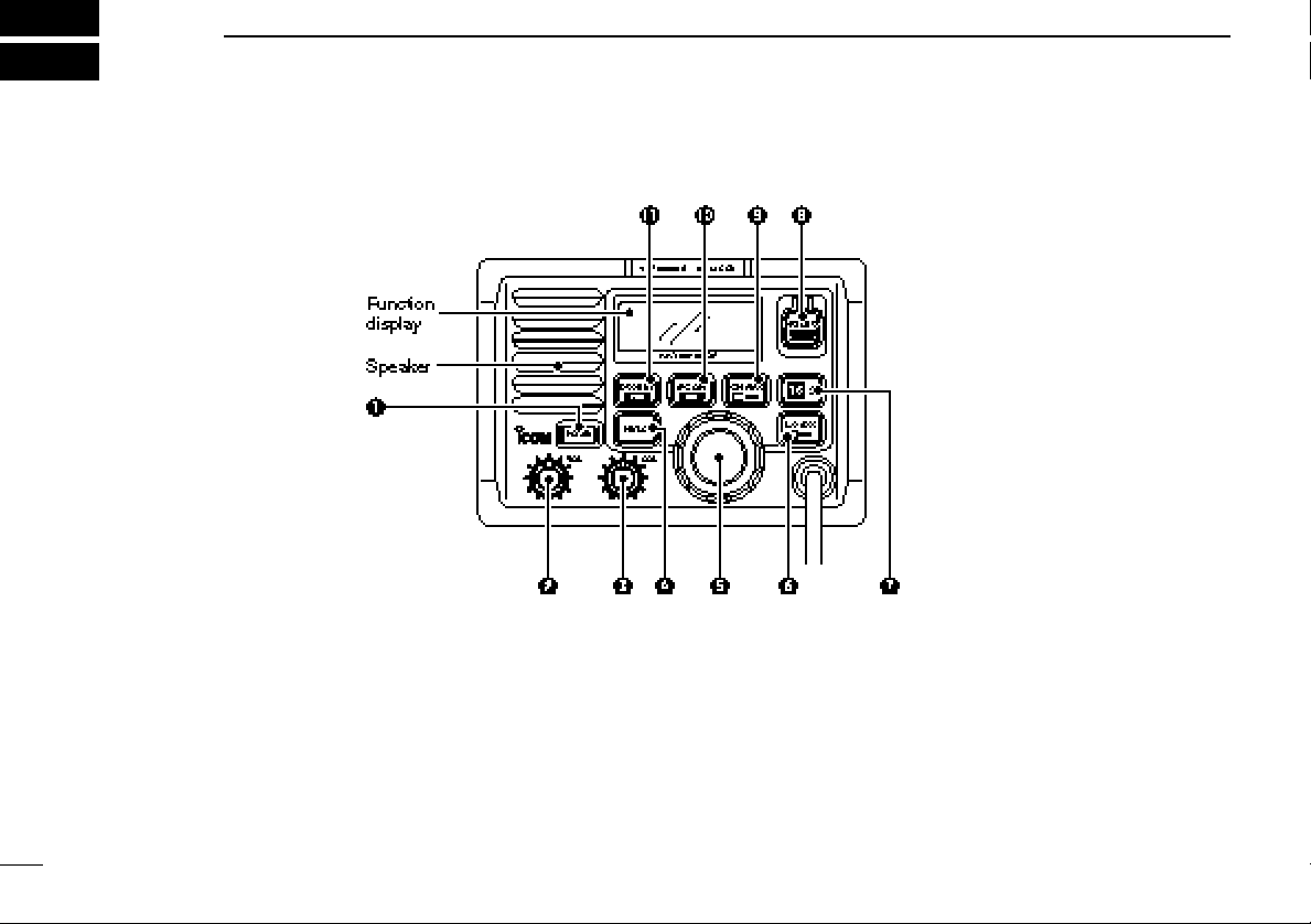
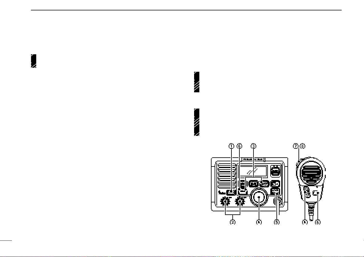
■ Panel description
q POWER SWITCH [POWER]
Push to toggle the transceiver power ON and OFF.
w VOLUME CONTROL [VOL]
Adjusts the audio level. (p. 8)
e SQUELCH CONTROL [SQL]
Sets the squelch threshold level. (p. 8)
2
r TRANSMIT POWER SWITCH [HI/LO]
➥ Toggles high and low power when pushed. (p. 8)
• Some channels are set to low power only.
➥ While pushing this switch, other switches perform sec-
ondary functions.
t CHANNEL SELECTOR [CHANNEL]
➥ Rotate [CHANNEL] to select the operating channels, set
mode contents, etc. (p. 8)

PANEL DESCRIPTION
2
➥ While pushing [HI/LO], rotate [CHANNEL] to adjust the
brightness of the LCD and switch backlight.
y ATTENUATOR/INTERCOM/SCRAMBLER SWITCH
[LO/DX•IC•SCR]
➥ Toggles the attenuator function ON and OFF when
pushed momentarily. (p. 8)
•“LOCAL” appears when the attenuator is in use. The order of
indication precedence is “LOCAL,” “SP OFF” and “CALL.”
➥ Activates an optional intercom function when pushed for
1 sec. (p. 29)
➥ Calls optional HM-127
when pushed and held while in intercom mode. (p. 29)
➥ While pushing [HI/LO], activates an optional voice
scrambler function. (p. 10)
•The optional voice scrambler function cannot be used on
channel 16 and 70.
u CHANNEL 16/CALL CHANNEL SWITCH [16•9]
➥ Selects channel 16 when pushed. (p. 6)
➥ Selects call channel when pushed for 1 sec. (p. 6)
•“CALL” appears when call channel is selected. “LOCAL” and
“SP OFF” indications have priority.
➥ Push for 3 sec. to enter call channel programming con-
dition when call channel is selected. (p. 9)
➥ While pushing [HI/LO], enters memory name program-
ming condition. (p. 9)
➥ Enters set mode when pushed while turning power ON.
(p. 30)
REMOTE-CONTROL MICROPHONE
i DISTRESS SWITCH [DISTRESS]
Transmits distress call when pushed for 5 sec. (p. 16)
o CHANNEL/DUALWATCH/TRI-WATCH SWITCH
[CH/WX•DW•U/I/C]
➥ Selects and toggles the regular channels and weather
channel when pushed momentarily. (pgs. 6, 7)
➥ While pushing [HI/LO], selects one of 3 regular channels
in sequence when pushed. (pgs. 6, 7)
•International, U.S.A. and Canadian channels are available for
regular channels.
➥ Starts dualwatch or tri-watch when pushed for 1 sec.
(p. 11)
➥ Stops dualwatch or tri-watch when either is activated.
!0 SCAN SWITCH [SCAN•TAG] (p. 13)
➥ Starts and stops normal or priority scan when tag chan-
nels are programmed.
➥ Push [SCAN•TAG] for 1 sec. to set the displayed chan-
nel as a tag (scanned) channel.
➥ While pushing [HI/LO], push for 3 sec. to clear all tag
channels.
!1 DSC/POSITION SWITCH [DSC/ENT•POS]
➥ Selects the DSC menu when pushed. (p. 14)
➥ Shows current position and time from an optional GPS
receiver, etc. when pushed for 1 sec. (p. 15)
3

PANEL DESCRIPTION
2
■ Function display
q BUSY/TRANSMIT INDICATOR (p. 8)
➥ “BUSY” appears when receiving a signal or when the
squelch opens.
➥ “TX” appears while transmitting.
w POWER INDICATOR (p. 8)
➥ “25W” appears when high power is selected.
➥ “1W” appears when low power is selected.
e TAG CHANNEL INDICATOR (p. 13)
Appears when a tag channel is selected.
r CHANNEL NAME INDICATOR
➥ Channel comment appears if programmed. (p. 9)
➥ “Low battery” flashes when the battery voltage drops to
approx. 10 V DC or below.
➥ “DUAL” appears during dualwatch; “TRI” appears dur-
ing tri-watch. (p. 11)
t SCRAMBLER INDICATOR (p. 10)
Appears when an optional voice scrambler is activated.
y DUPLEX INDICATOR (p. 6)
Appears when a duplex channel is selected.
u CHANNEL NUMBER READOUT
➥ Indicates the selected operating channel number. “A”
appears when a simplex channel is selected. (p. 6)
➥ In set mode, indicates the selected condition. (p. 30)
i CHANNEL GROUP INDICATOR (p. 6)
Indicates whether an International (INT), U.S.A. (USA),
Canadian (CANADA) or weather (WX) channel is selected.
o CALL CHANNEL INDICATOR
➥ “CALL” appears when the call channel is selected. (p.
6)
➥ “SP OFF” appears when the internal speaker is turned
OFF in set mode. (p. 32)
➥ “LOCAL” appears when the attenuator is in use. (p. 8)
•The order of indication precedence is “LOCAL,” “SP OFF” and
4
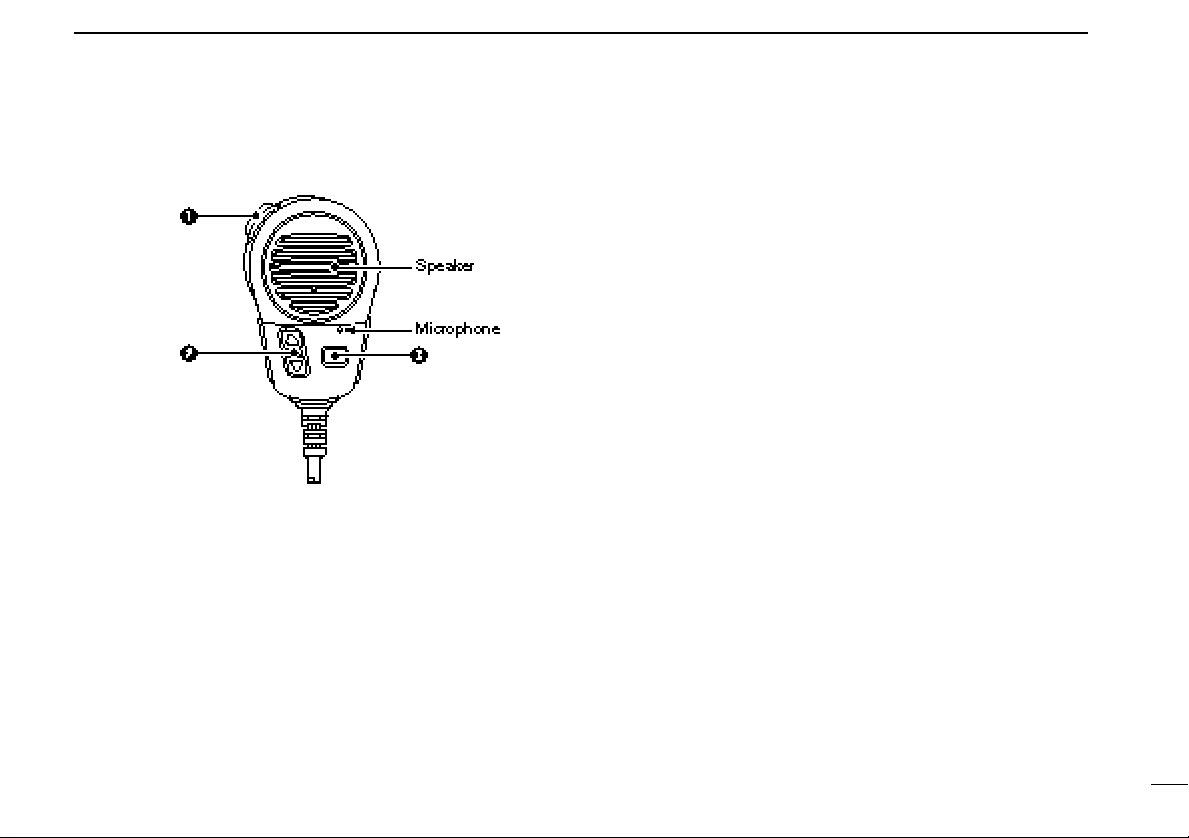
■ Microphone
q PTT SWITCH [PTT]
Push and hold to transmit; release to receive. (p. 8)
w CHANNEL UP/DOWN SWITCHES [YY]/[ZZ]
Push either switch to change the operating memory channel, set mode contents, etc. (p. 8)
PANEL DESCRIPTION
2
e TRANSMIT POWER SWITCH [HI/LO]
➥ Same as the [HI/LO] switch on the front panel. (p. 8)
➥ While pushing [HI/LO] on the supplied microphone, turn
power ON to toggle the lock function ON and OFF. (p.
5
3
BASIC OPERATION
■ Channel selection
Channel 16
Channel 16 is the distress and safety channel. It is used for
establishing initial contact with another station and for emergency communications. Channel 16 is monitored during both
dualwatch and tri-watch. While standing by, you must monitor
channel 16.
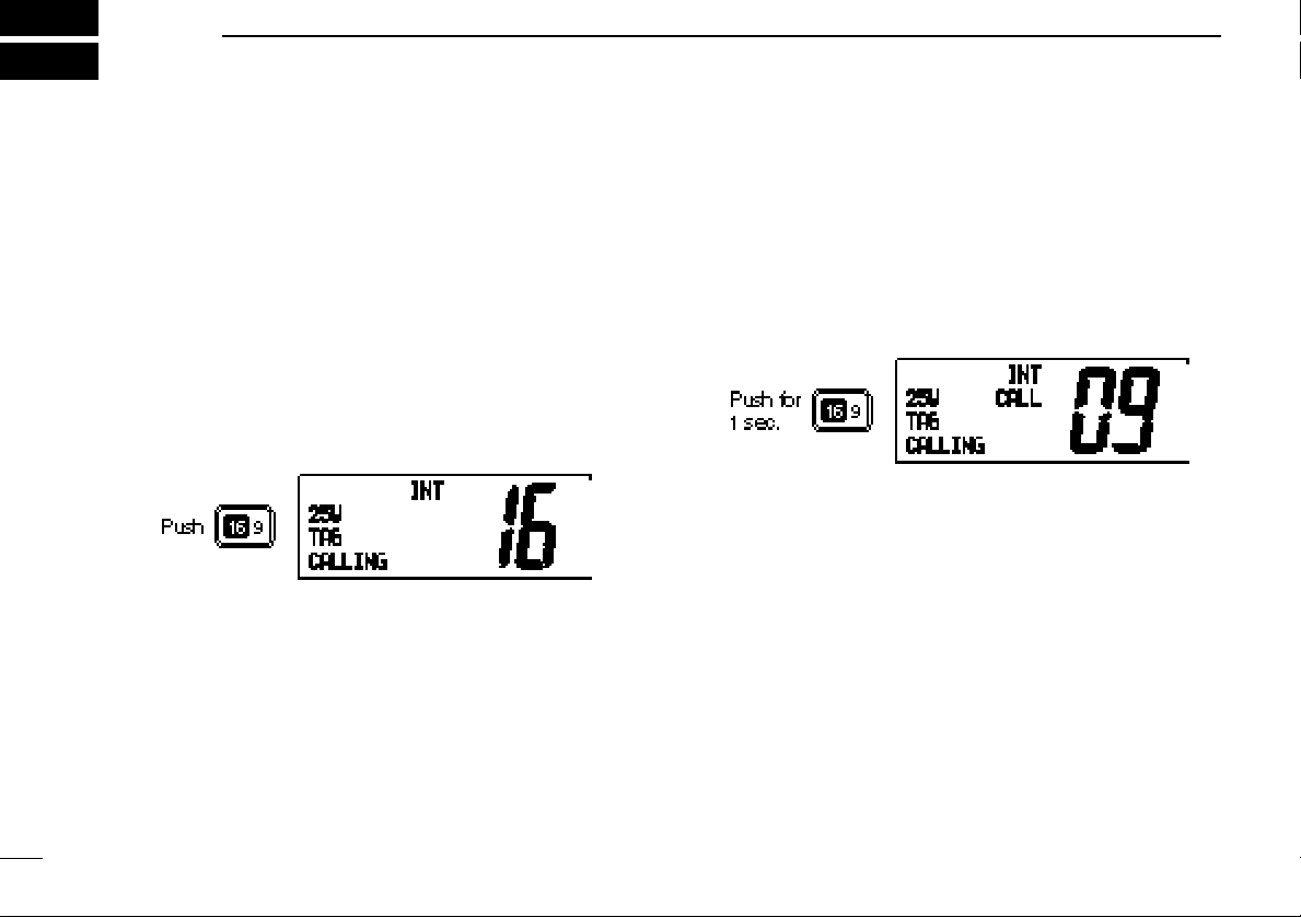
➥ Push [16•9] momentarily to select channel 16.
➥ Push [CH/WX] to return to the condition before selecting
channel 16, or rotate [CHANNEL] to select operating channel.
➥ Push [16•9] for 1 sec. to select the call channel of the se-
lected channel group.
•“CALL” and call channel number appear.
• Each channel group may have an independent call channel after
changing a call channel.
➥ Push [CH/WX] to return to the condition before selecting
call channel
channel.
, or rotate [CHANNEL] to select operating
U.S.A., Canadian and international
channels
There are 57 U.S.A., 61 Canadian and 57 international channels. These channel groups may be specified for the operat-
Channel 9 (Call channel)
Each regular channel group has a separate leisure-use call
channel. The call channel is monitored during tri-watch. The
call channels can be programmed (p. 9) and are used to store
your most often used channels in each channel group for
quick recall.
6
ing area.
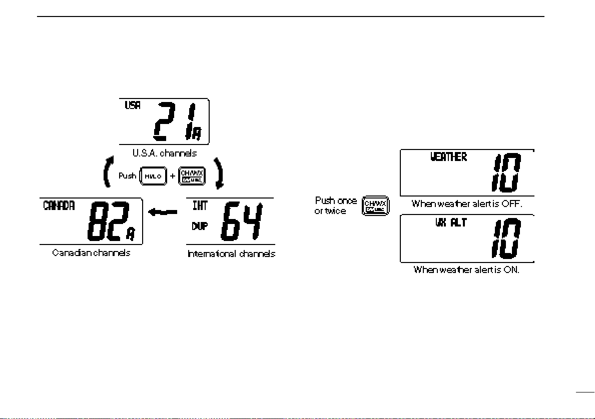
q Push [CH/WX] to select a regular channel.
• If a weather channel appears, push [CH/WX] again.
w Push [CH/WX•U/I/C] while pushing [HI/LO] to change the
channel group, if necessary.
•U.S.A., International (INT) and Canadian channels can be se-
lected in sequence.
e Rotate the channel selector to select a channel.
BASIC OPERATION
3
• “DUP” appears for duplex channels.
• “A” appears for simplex channels.
Weather channels
There are 10 weather channels. Used for monitoring weather
channels from the NOAA (National Oceanographic and Atmospheric Administration) broadcasts.
The transceiver can detect a weather alert tone on the selected weather channel while receiving the channel, during
standby on a regular channel or while scanning. See
“Weather alert” on p. 31.
q Push [CH/WX] once or twice to select a weather channel.
•“WEATHER” appears when a weather channel is selected. “WX
ALT” appears when the weather alert function is in use. (p. 31)
w Rotate the channel selector to select a channel.
• Channels are memorized separately for each channel group.
■ Microphone lock function
The microphone lock function electrically locks the [Y]/[Z]
and [HI/LO] switches on the supplied microphone. This prevents accidental channel changes and accidental function access.
7
BASIC OPERATION
3
■ Receiving and transmitting
CAUTION: Transmitting without an antenna may dam-
age the transceiver.
q Push [POWER] to turn power ON.
w Set the audio and squelch levels.
➥ Rotate [SQL] fully counterclockwise in advance.
➥ Rotate [VOL] to adjust the audio output level.
➥ Rotate [SQL] clockwise until the noise disappears.
e To change the channel group, push [CH/WX•DW•U/I/C]
while pushing [HI/LO]. (p. 6)
r Rotate the channel selector or push [Y]/[Z] on the micro-
phone to select the desired channel.
•When receiving a signal, “BUSY” appears and audio is emitted
from the speaker.
•Further adjustment of [VOL] may be necessary at this point.
•Use the optional voice scrambler function for privacy. (p. 10)
t Push [LO/DX] to turn the receive attenuator ON or OFF if
necessary.
•“LOCAL” appears when the receive attenuator is in use.
y Push [HI/LO] to select the output power if necessary.
•“25W” or “1W” appears when high or low power is selected, respectively.
•Choose low power to conserve power, choose high power for
longer distance communications.
• Some channels are for low power only.
u Push and hold [PTT] to transmit, then speak into the mi-
crophone.
• “TX” appears.
• Channel 70 cannot be used for transmission (for GMDSS use).
Simplex channels, 3, 21, 23, 61, 64, 81, 82 and 83 CAN-
NOT be lawfully used by the general public in U.S.A. waters.
i Release [PTT] to receive.
IMPORTANT: To maximize the readability of your transmitted signal, pause a few sec. after pushing [PTT], hold
the microphone 4 to 6 inches (10 to 15 cm) from your
mouth and speak at a normal voice level.
8
BASIC OPERATION
3
■ Call channel programming
The call channel is used to select channel 9, however, you
can program your most often-used channels in each channel
group for quick recall.
q While pushing [HI/LO], push [CH/WX•DW•U/I/C] one or
more times to select the desired channel group (U.S.A., International, Canada) to be programmed.
w Push [16•9] for 1 sec. to select the call channel of the se-
lected channel group.
•“CALL” and call channel number appear.
•The order of indication precedence is “LOCAL,” “SP OFF” and
“CALL.”
e Push [16•9] again for 3 sec.
(until long beep changes to
2 short beeps) to enter call
channel programming condition.
•Channel number starts flashing.
r Rotate the channel selector
to select the desired channel.
t Push [16•9] to program the displayed channel as the call
channel.
• Push [CH/WX] to cancel.
•The channel number stops flashing.
■ Channel names
Memory channels can be tagged with alphanumeric names
of up to 10 characters each.
Capital letters, small letters, numerals, some symbols (! " # $
% & ' ( ) ✱ + ,– .⁄ ) and spaces can be used.
q Select the desired memory channel.
• Cancel dual watch, tri-watch or scan in advance.
w While pushing [HI/LO], push [16•9] to edit memory chan-
nel name.
• A cursor appears and blinks.
e Select the desired character by rotating the channel selec-
tor or by pushing [Y]/[Z] on the microphone.
• Push [SCAN] or [CH/WX] for cursor movement.
r Push [16•9] to input and set the name.
• Push [HI/LO] to cancel.
•The cursor disappears.
t Repeat steps q to r to program other memory channel
names, if desired.
9
BASIC OPERATION
3
■ Optional voice scrambler operation
Activating the scrambler
The optional voice scrambler provides private communications. In order to receive or send scrambled transmissions
you must first activate the scrambler function. To activate the
function, an optional UT-98 or UT-112 is necessary. See p. 33
for selecting the unit. Ask your dealer for details.
The scrambler function automatically turns OFF when
channel 16 or 70 is selected.
q Select an operating channel other than channel 16 and 70.
w While pushing [HI/LO], push [LO/DX•IC/SCR] to toggle an
optional scrambler function ON or OFF.
• “SC” appears.
e To turn the scrambler function OFF, repeat step w.
• “SC” disappears.
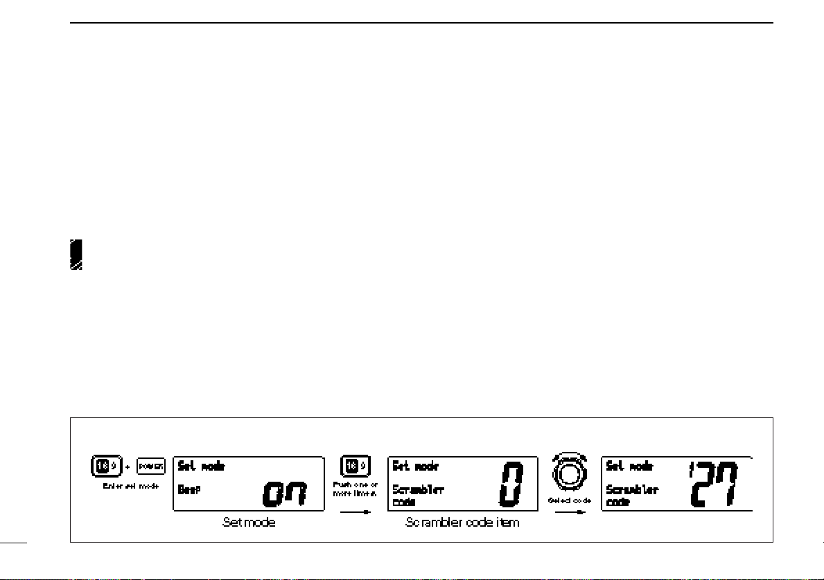
[Example]: Programming scrambler code 127.
Programming scrambler codes
There are 128 or 32 codes (0 to 127 or 1 to 32) available for
programming when the optional UT-98 or UT-112 is installed.
In order to understand one another, all transceivers in your
group must have the same scramble code. This function may
not be available depending on dealer setting.
q Turn power OFF.
w While pushing [16•9], turn power ON to enter set mode.
e After the display appears, release [16•9].
r Push [16•9] one or more times to select the scrambler
code item.
• “Scrambler code” appears.
t Rotate the channel selector to select the desired scram-
bler code.
y Turn power OFF, then ON again to exit set mode.
10

DUAL WATCH/TRI-WATCH
4
■ Description
Dualwatch monitors channel 16 while you are receiving another channel; tri-watch monitors channel 16 and the call
channel while receiving another channel.
DUALWATCH/TRI-WATCH SIMULATION
•If a signal is received on channel 16, dualwatch/tri-watch pauses
on channel 16 until the signal disappears.
•If a signal is received on the call channel during tri-watch, triwatch becomes dualwatch until the signal disappears.
•To transmit on the selected channel during dualwatch/tri-watch,
push and hold [PTT].
■ Operation
q Select the desired operating channel.
w Select dualwatch or tri-watch in set mode. (p. 31)
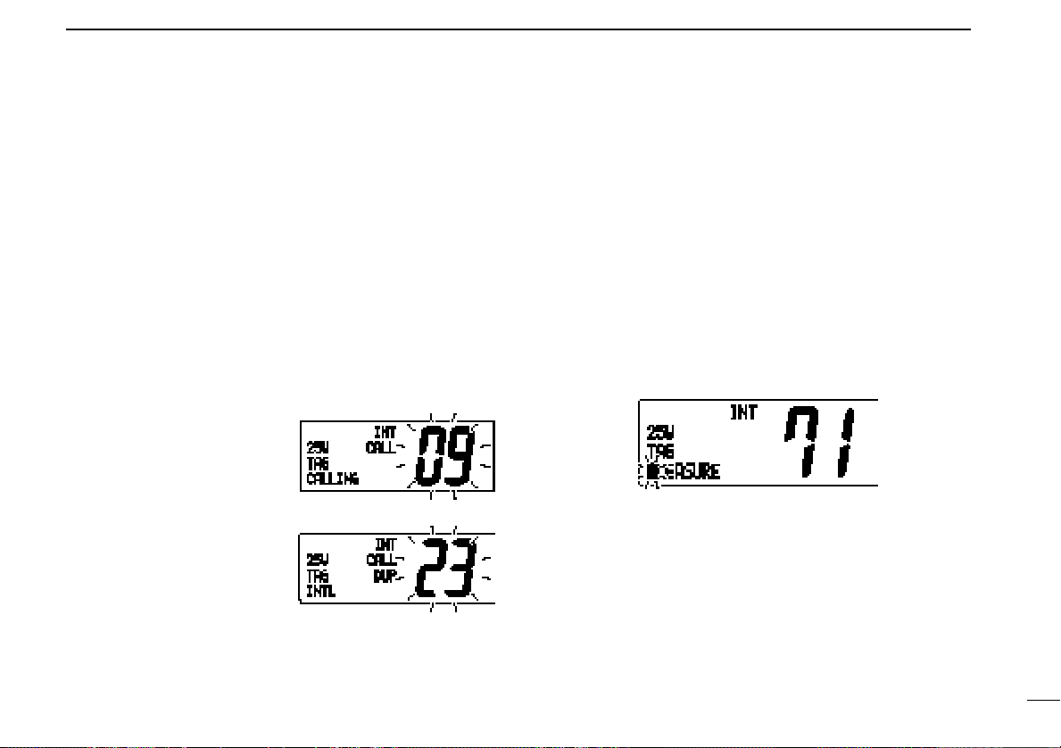
e Push [CH/WX•DW•U/I/C] for 1 sec. to start dualwatch or
tri-watch.
• “DUAL” appears during dualwatch; “TRI” appears during tri-
watch.
• Beep tone sounds when a signal is received on channel 16.
r To cancel dualwatch/tri-watch, push [CH/WX•DW•U/I/C]
[Example]: Operating tri-watch on INT channel 25.
11

5
SCAN OPERATIONS
■ Scan types
Scanning is an efficient way to locate signals quickly over a
wide frequency range. The transceiver has priority scan and
normal scan.
When the weather alert function is in use, the selected
weather channel is checked while scanning. (p. 31)
PRIORITY SCAN
Priority scan searches through all tag channels in sequence while monitoring channel 16. When a signal is detected on channel 16, scan pauses until the signal disappears; when a signal is detected on a channel other than
channel 16, scan becomes dualwatch until the signal disappears.
Set the tag channels (scanned channel) before scanning.
Clear the tag channels which inconveniently stop scanning,
such as digital communication use.
Choose priority or normal scan in set mode. (p. 31)
NORMAL SCAN
Normal scan, like priority scan, searches through all tag
channels in sequence. However, unlike priority scan, channel 16 is not checked unless channel 16 is set as a tag
channel.
12
SCAN OPERATION
5
■ Setting tag channels
For more efficient scanning, add desired channels as tag
channels or clear tag channels for unwanted channels. Channels set as non-tag channels will be skipped during scanning.
Tag channels can be assigned to each channel group
(U.S.A., International, Canada) independently.
q While pushing [HI/LO], push [CH/WX•DW•U/I/C] one or
more times to select the desired channel group, if desired.
w Select the desired channel to set as a tag channel.
e Push [SCAN•TAG] for 1 sec. to set the displayed channel
as a tag channel.
• “TAG” appears in the function display.
r To cancel the tag channel setting, repeat e.
• “TAG” disappears.
• Clearing all tag channels in the selected channel group
➥ While pushing [HI/LO], push [SCAN•TAG] for 3 sec. to
clear all tag channels in the channel group.
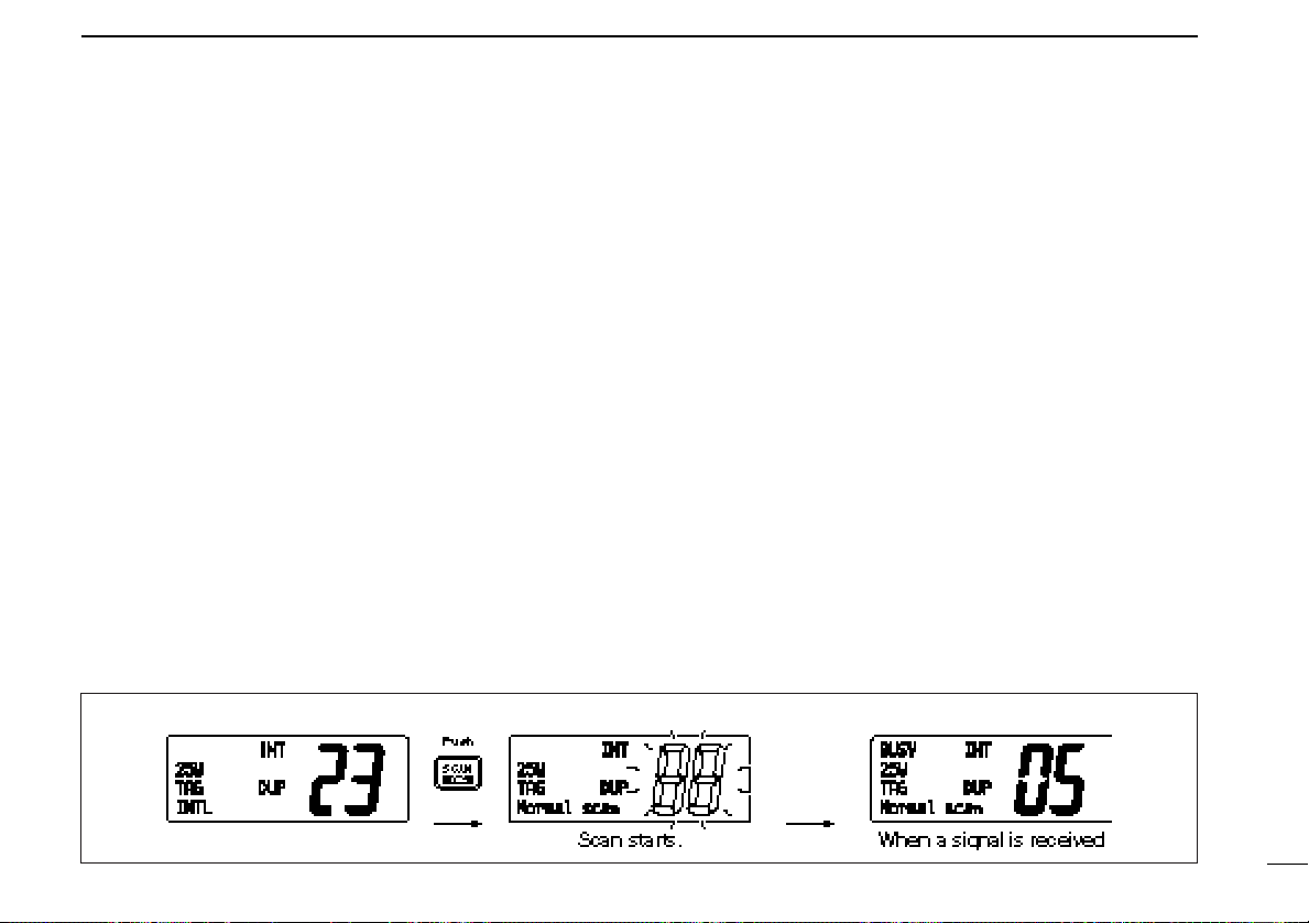
[Example]: Starting a normal scan.
■ Starting a scan
Set scan type (priority or normal scan) and scan resume timer
in advance using set mode. (p. 31)
q Set tag channels as described at left.
w Make sure the squelch is closed to start a scan.
e While pushing [HI/LO], push [CH/WX•DW•U/I/C] one or
more times to select the desired channel group, if desired.
r Push [SCAN] to start priority or normal scan.
• “Pri scan 16” or “Normal scan” appears in the function display.
•When a signal is detected, scan pauses until the signal disappears or resumes after pausing 5 sec. according to set mode setting. (Channel 16 is still monitored during priority scan.)
•Rotate the channel selector to check the scanning tag channels,
to change the scanning direction or resume the scan manually.
•“16” flashes and a beep tone sounds when a signal is received
on channel 16 during priority scan.
•Push [SCAN•TAG] for 1 sec. to set the paused channel as a tag
channel.
t To stop the scan, push [SCAN].
13
6
DSC OPERATION
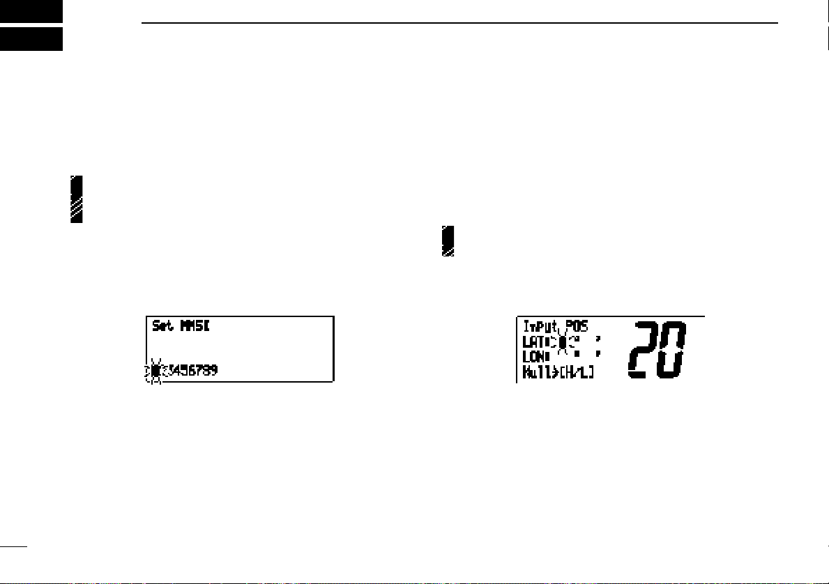
■ MMSI code programming
The 9-digit MMSI (DSC self ID) code can be programmed at
power ON.
This function is not available when the MMSI code has
been programmed by the dealer. This code programming
can be performed only 2 times.
q Turn power OFF.
w While pushing [DSC/ENT], turn power ON to enter MMSI
code programming condition.
e After the display appears, release [DSC/ENT].
r Select the desired number by rotating the channel selector.
t Push [CH/WX] to advance the cursor.
• Push [SCAN] to move the cursor backward.
y Repeat steps r and t to input 9 digit code.
u Push [DSC/ENT] to input and set the code.
• The previously selected channel appears.
■
Position and time programming
A distress call should include the ship’s position and time. If
no GPS is connected, your position and UTC (Universal Time
Coordinated) time should be input. They are included automatically when a GPS receiver (NMEA0183 ver. 2.0) is connected.
This function is not available when an optional GPS receiver (NMEA0183 ver. 2.0) is connected.
q Push [DSC/ENT] twice to enter the position programming
condition.
w Rotate the channel selector to select the digit of your posi-
tion.
e Push [CH/WX] to advance the cursor.
• Push [SCAN] to move the cursor backward.
• Push [HI/LO] to clear the position data.
14

DSC OPERATION
6
r Push [DSC/ENT] to set the position and advance to time
setting condition.
• Push [LO/DX] to abandon the setting and exit the condition.
t Rotate the channel selector to select the digit of current
UTC time.
y Push [CH/WX] to advance the cursor.
• Push [SCAN] to move the cursor backward.
• Push [HI/LO] to clear the time.
u Push [DSC/ENT] to set the time.
•Push [LO/DX] to abandon the setting and exit the condition.
■ Position indication
When an optional GPS receiver (NMEA0183 ver. 2.0) is connected, the transceiver can display the current position and
time. When no GPS receiver is connected, the transceiver
displays the manually entered position and time.
A GPS receiver appropriate for the IC-M502 is not supplied
from Icom. An NMEA0183 ver. 2.0 is required for position indication. Ask your dealer about the GPS receiver.
➥ Push [DSC/ENT•POS] for 1 sec. to display the current po-
sition and time.
•“MNL” (manual) appears instead of the “GPS” indication when
the position data is entered manually.
15
 Loading...