


Repair Parts Manual Manuel De Pièces De Rechange
YTA1946 / 96048005500
Please read the operator's manual carefully and make sure you understand the instructions before using the machine.
586 26 35-49 |
|
|
Lisez très attentivement et soyez certain de comprende |
English/French |
|
|
ces instructions avant d’utiliser cette machine. |
||
|
|
HOW TO USE THIS MANUAL
This manual is designed to provide the customer with a means to identify the parts on his/her tractor when ordering repair parts. The illustrations may or may not represent the actual assemblies; therefore, it is not recommended to use this manual as a guide to assemble or disassemble the tractor. Some hardware and parts are drawn larger in order to more readily identify them.
Each tractor has its own model number. |
|
|
The model number for your tractor can be found on the fender under the seat. |
|
|
When ordering parts, always give the following information: |
|
|
• |
Product - “TRACTOR” |
|
• |
MODEL NUMBER - “YTA1946" (96048005500)” |
|
• |
Part Number |
|
• |
Part Description |
|
TABLE OF CONTENTS |
|
|
SCHEMATIC ....................................................................................................................................................................... |
3 |
|
ELECTRICAL.................................................................................................................................................................. |
4-5 |
|
CHASSIS ........................................................................................................................................................................ |
6-7 |
|
DRIVE.............................................................................................................................................................................. |
8-9 |
|
ENGINE....................................................................................................................................................................... |
10-11 |
|
STEERING .................................................................................................................................................................. |
12-13 |
|
MOWER DECK ........................................................................................................................................................... |
14-15 |
|
MOWER LIFT.................................................................................................................................................................... |
16 |
|
SEAT |
................................................................................................................................................................................. |
17 |
DECALS............................................................................................................................................................................ |
18 |
|
COMO UTILIZAR ESTE MANUAL
Este manual está diseñado para brindarle al comprador un medio para identificar las piezas del tractor para cuando necesite hacer el pedido de un repuesto. Las ilustraciones pueden o no representar los ensambles reales; por lo tanto, no se recomienda utilizar este manual como una guía para ensamblar o desarmar el tractor. Algunos accesorios y piezas están dibujados en tamaños más grandes para identificarlos con mayor facilidad.
Cada tractor tiene su propio número de modelo. |
|
|
El número de modelo del tractor se encuentra en el guardabarros debajo del asiento. |
|
|
Cuando haga el pedido de una pieza, siempre brinde la siguiente información: |
|
|
• |
Producto: ”TRACTOR” |
|
• |
NÚMERO DE MODELO: “YTA1946"(96048005500)” |
|
• |
Número de pieza |
|
• |
Descripción de la pieza |
|
ÍNDICE |
|
|
DIAGRAMA....................................................................................................................................................................... |
19 |
|
DIAGRAMA ELÉCTRICO........................................................................................................................................... |
20-21 |
|
CHASIS....................................................................................................................................................................... |
22-23 |
|
TRANSMISIÓN ........................................................................................................................................................... |
24-25 |
|
MOTOR ....................................................................................................................................................................... |
26-27 |
|
DIRECCIÓN ................................................................................................................................................................ |
28-29 |
|
PLATAFORMA DE LA CORTADORA DE CÉSPED.................................................................................................. |
30-31 |
|
ELEVACIÓN DE LA CORTADORA DE CÉSPED............................................................................................................ |
32 |
|
ASIENTO........................................................................................................................................................................... |
33 |
|
CALCOMANÍAS................................................................................................................................................................ |
34 |
|
2
TRACTOR - MODEL NO. YTA1946 (96048005500), PRODUCT NO. 960 48 00-55
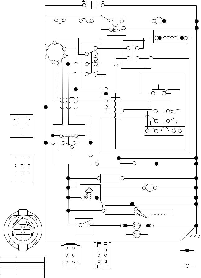
SCHEMATIC
SCH13
87
86 87A 85
30
RELAY

 C
C 
 F
F 
 H
H

 B
B 
 E
E 
 G
G

 A
A 
 D
D
PTO SWITCH
(MATING SIDE)
|
|
|
BATTERY |
SOLENOID |
|
|
|
|
|
|
STARTER |
||
|
|
|
|
|
|
|
|
A |
|
RED |
|
|
M |
|
|
|
|
|
|
|
|
|
RED |
FUSE |
|
|
|
AMMETER |
|
|
BLACK |
|
||
(OPTIONAL) |
|
|
|
|
||
|
|
|
|
|
||
|
WHITE |
|
PTO SWITCH |
|
|
ELECTRIC CLUTCH |
|
|
|
WHITE |
BLACK |
||
|
|
|
|
|||
|
|
|
(DISENGAGED) |
|
|
|
S |
BLACK |
H |
WHITE |
|
|
|
B |
M |
|
|
|
|
|
C |
|
|
|
|
||
|
A1 |
|
|
|
|
|
G |
|
|
|
|
GRAY |
|
A2 |
|
|
|
|
||
L |
A |
D |
|
CLUTCH/BRAKE |
|
|
|
|
RED |
|
|||
|
|
BLUE |
|
|
(PEDAL UP) |
|
|
|
B |
E |
BLACK |
|
|
|
|
|
|
|
REVERSE SWITCH |
|
|
|
|
|
|
|
|
|
|
|
|
|
|
(NOT IN REVERSE) |
|
|
|
BLACK |
|
|
|
|
|
|
BLACK |
|
|
|
|
|
|
BLACK |
2 |
BLACK |
SEAT SWITCH |
|
|
|
3 |
|
||
|
|
|
|
BLACK |
(NOT OCCUPIED) |
|
|
|
|
BLACK |
1 |
BLACK |
|
|
|
|
|
|
|
|
|
|
|
|
6 |
GRAY |
|
|
BLUE |
BLACK |
/WHITE |
|
JUNCTION |
|
|
|
|
CONNECTOR |
|
||
|
|
|
BLACK |
|
||
|
85 |
86 |
|
|
|
|
|
|
|
|
|
||
|
30 |
87 |
|
|
|
SHORTING |
|
|
CHASSIS |
CONNECTOR |
|||
|
|
|
|
|
||
|
|
87A |
|
HARNESS |
|
|
|
|
|
|
|
|
|
|
|
BLACK |
|
|
|
|
|
|
IGNITION |
|
SPARK |
|
|
|
UNIT |
|
PLUGS GAP |
|
|
|
|
|
(2 PLUGS ON |
|
|
|
(OPTIONAL) |
|
TWIN CYL. ENGINES) |
|
|
|
|
|
|
|
|
BLUE |
HOUR |
|
BLACK |
|
BLACK |
|
METER |
|
|
|
FUEL |
BLUE |
|
12V |
BLACK |
|
|
|
|
|
||
|
LINE |
|
|
|
|
|
|
|
|
POWER OUTLET |
|
|
BLUE |
|
|
(OPTIONAL) |
|
|
|
CHARGING SYSTEM OUTPUT |
|
||
|
FUEL SHUT-OFF |
9-15 AMP DC @ 3600 RPM |
|
||
|
SOLENOID |
|
|
|
|
|
(IF EQUIPPED) |
REGULATOR |
STATOR |
|
|
|
RED |
|
|||
|
|
|
|
||
|
ORANGE |
|
28 VOLTS AC @ 3600 RPM (REGULATOR DISCONNECTED) |
||
|
|
|
|||
|
|
BROWN |
|
|
BLACK |
|
LIGHT |
|
|
|
|
|
SWITCH |
|
|
|
|
|
|
|
|
HEADLIGHTS |
|
|
|
|
3 |
6 |
6 |
3 |
|
IGNITION SWITCH |
|
|
|||||
2 |
5 |
5 |
2 |
||||
POSITION |
CIRCUIT |
“MAKE” |
|||||
|
|
4 |
1 |
||||
OFF |
M+G+A1 |
|
1 |
4 |
|||
|
|
|
|||||
RUN/OVERRIDE |
B+A1 |
|
|
|
|
|
|
RUN |
B+A1 |
L+A2 |
CHASSIS HARNESS |
DASH HARNESS |
|||
START |
B + S + A1 |
|
CONNECTOR |
CONNECTOR |
|||
|
(MATING SIDE) |
|
|
||||
|
|
|
|
|
|||
WIRING INSULATED CLIPS
NOTE: IF WIRING INSULATED CLIPS WERE REMOVED FOR SERVICING OF UNIT, THEY SHOULD BE RE-INSTALLED TO PROPERLY SECURE YOUR WIRING.
NON-REMOVABLE CONNECTIONS
REMOVABLE CONNECTIONS
3
TRACTOR - MODEL NO. YTA1946 (96048005500), PRODUCT NO. 960 48 00-55 |
|||||
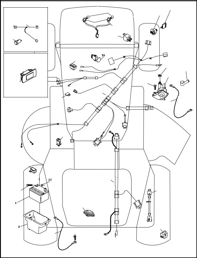
ELECTRICAL |
|
|
|
|
|
T21S |
|
|
|
33 |
|
With 12V Outlet Option |
|
|
22 |
|
|
|
|
30 |
|
||
|
|
|
|
|
|
103 |
|
79 |
|
21 |
|
|
|
|
|
|
|
59 |
|
|
|
81 |
|
|
|
|
|
|
|
With Service Minder Option |
|
34 |
|
|
|
|
|
|
|
|
|
|
|
|
|
27 |
42 |
|
|
|
|
|
|
|
|
|
|
43 |
|
46 |
|
|
|
41 |
|
|
|
|
40 |
|
|
|
26 |
|
|
25 |
|
|
|
|
|
|
|
|
|
16 |
|
|
|
90 |
|
|
|
|
|
|
|
|
71 |
|
|
2 |
|
|
|
102 |
|
|
|
29 |
|
|
|
|
|
|
|
105 |
|
28 |
|
55 |
|
|
|
|
|
|
4 |
|
|
TRACTOR - MODEL NO. YTA1946 (96048005500), PRODUCT NO. 960 48 00-55
ELECTRICAL
KEY |
PART |
|
NO. |
NO. |
DESCRIPTION |
1 |
532 16 34-65 |
Battery |
2 |
874 76 04-12 Bolt Hex Head 1/4-20 x 3/4 |
|
8 |
532 19 32-28 |
Box Battery |
16 |
532 17 61-38 Switch Interlock Push-In |
|
21 |
532 40 02-52 Harness Socket Light w/4152J |
|
22 |
532 00 41-52 |
Bulb Light |
25 |
585 55 55-01 |
Cable Starter |
26 |
532 17 51-58 |
Fuse |
27 |
873 51 04-00 Nut Keps Hex 1/4-20 unc |
|
28 |
532 42 16-86 |
Cable, Ground |
29 |
532 40 15-45 |
Switch, Seat |
30 |
532 19 33-50 |
Switch, Ign |
33 |
532 41 19-35 |
Key/Chain |
34 |
532 11 07-12 Switch Light/Reset |
|
40581 02 28-01 Harness Ign. Dash
41817 72 04-08 Screw Thd Cut 1/4-20 x 1/2
42 |
532 13 15-63 |
Cover, Terminal |
43 |
532 19 25-07 |
Solenoid |
46 |
532 40 17-63 Gauge Serviceminder Hrmtr |
|
50 |
532 17 46-51 Switch PTO 8 Terminal |
|
55 |
817 06 05-12 Screw Thdrol 5/16-18 x 3/4 TYTT |
|
71 |
532 44 15-44 Harness Ign. Chassis |
|
79 |
532 17 52-42 Socket Asm. Bulb |
|
81 |
532 40 96-15 Relay Harness Sealed |
|
90 |
532 43 53-95 |
Cover Terminal |
102 |
581 02 34-01 |
Harness Pigtail |
105 |
532 40 75-68 |
Switch Reverse |
NOTE: All component dimensions given in U.S. inches 1 inch = 25.4 mm
5

TRACTOR - MODEL NO. YTA1946 (96048005500), PRODUCT NO. 960 48 00-55
CHASSIS
|
|
|
|
|
|
15 |
|
|
|
|
|
|
208 |
|
|
|
|
|
|
3 |
|
|
204 |
|
|
|
297 |
|
|
|
|
|
|
|
|
|
203 |
|
|
|
25 |
|
|
|
|
130 |
|
191 |
|
|
14 |
214 |
|
|
207 |
|
|
|
|
|
||
|
|
|
|
130 |
|
|
|
|
|
|
|
|
|
|
|
206 |
|
|
|
|
|
|
137 234 |
|
|
130 |
18 |
|
|
|
|
|
||
|
|
5 |
|
|
|
|
336 |
176 |
137 |
|
|
|
|
|
|
|
|
|
|
|
|
|
|
234 |
|
|
151 |
|
|
|
|
|
202 |
|
|
|
|
|
|
|
|
350 |
|
|
176 |
|
205 |
|
|
|
176 |
|
|
150 |
|
|
|
175 |
|
|
|
|
|
|
|
|
335 |
|
|
|
|
|
177 |
|
|
|
|
|
|
|
|
|
|
|
|
195 |
|
|
|
130 |
|
|
176 |
176 |
|
350 |
|
|
|
|
235 |
68 |
|
|
|
|
|
|
|
||
196 |
138 |
36 |
|
|
|
182 |
236 |
|
235 |
|
130 |
|
194 |
|
|
|
34 |
|
|
||||||
181 |
|
|
|
68 |
|
|
|
|
|
|||
|
|
|
36 |
194 |
|
68 |
|
|
|
|
236 |
|
|
|
|
|
|
|
|
|
|
|
|
213 |
|
|
|
|
|
|
|
|
|
|
|
|
|
|
|
|
|
|
|
|
|
|
|
|
|
68 |
213 |
|
|
|
|
|
|
|
|
|
|
|
218 |
|
|
|
|
|
|
|
|
|
|
|
68 |
|
|
|
|
|
|
|
|
|
|
|
|
|
180 |
|
|
|
|
|
|
|
|
|
|
|
|
|
|
287 |
|
|
|
|
37 |
|
183 |
68 |
|
|
|
68 |
|
|
|
|
|
|
|
|
183 |
|
|
|
|
|
|
162 |
|
181 |
|
|
|
|
|
|
|
|
|
|
|
|
|
|
228 |
|
|
|
|
||
|
|
|
|
|
|
|
58 |
|
|
|
68 |
|
|
|
|
|
|
189 |
|
|
|
|
|
||
|
|
|
|
159 |
|
|
|
194 |
|
217 |
||
|
|
|
|
|
|
|
|
|
||||
|
|
|
|
|
|
|
|
|
|
|
189 |
|
159 |
189 |
228 |
52 |
|
|
|
159 |
152 |
159 |
chassis-tex_GT HUSQ_II_160 |
|
|
|
|
6
TRACTOR - MODEL NO. YTA1946 (96048005500), PRODUCT NO. 960 48 00-55
CHASSIS
KEY |
PART |
|
KEY |
PART |
|
NO. |
NO. |
DESCRIPTION |
NO. |
NO. |
DESCRIPTION |
3 |
532 44 44-81 |
Applique Sub Asm. |
191 |
532 43 74-55 Insert Reflective RH |
|
5 |
581 46 69-03 |
Dash |
194 |
873 90 05-00 Nut Lock Hex Flange 5/16-18 |
|
14 |
532 44 11-77 |
Hood |
195 |
532 40 41-37 Plug Hole Dash Lower |
|
15 |
532 43 97-33 |
Lens LH |
196 |
532 43 96-47 Console Asm. Deck Lift |
|
18 |
532 44 06-53 |
Grille |
202 |
532 43 97-28 Vent Side Hood RH |
|
25 |
532 44 33-85 |
Lens RH |
203 |
532 43 97-27 Vent Side Hood LH |
|
34 |
580 91 08-01 |
Plate Engine |
204 |
532 43 57-14 |
Vent Top Hood |
36 |
817 06 05-12 |
Screw 5/16-18 x 3/4 |
205 |
532 43 97-30 Trim Hood Side RH |
|
37 |
532 44 12-06 |
Fender |
206 |
532 43 97-29 Trim Hood Side LH |
|
52 |
873 68 05-00 |
Nut Lock 5/16-18 |
207 |
532 43 97-34 |
Bezel RH |
58 |
532 41 22-80 |
Drawbar Upper |
208 |
532 43 97-35 |
Bezel LH |
68 |
817 49 05-08 |
Screw Thdrol 5/16-18 x 1/2 |
213 |
874 76 05-12 Bolt 5/16-18 x 3/4 |
|
130 |
532 41 63-58 |
Screw #10 x 0.750 |
214 |
532 19 91-45 Clip Retainer Tinner |
|
137 |
532 40 75-90 |
Bumper Dash |
217 |
532 40 91-67 |
Rod Pivot |
138 |
532 43 97-47 |
Cupholder |
218 |
532 19 63-95 X-Piece Hood Stop |
|
150 |
532 43 99-21 |
Air Duct |
228 |
532 19 51-61 |
Stud Fastner |
151 |
532 43 66-70 |
Bracket Pivot |
234 |
532 40 47-42 |
Bumper Hood |
152 |
532 43 98-70 |
Shield Browning |
235 |
532 40 61-29 |
Spacer Fender |
159 |
817 00 06-12 |
Screw Hexwsh Thrd 3/8-16 x 3/4 |
236 |
873 93 05-00 Nut Lock 5/16-18 unc |
|
162 |
532 14 24-32 |
Screw |
287 |
817 60 04-06 Screw 1/4-20 x 3/8 |
|
175 |
532 19 63-04 |
Crossmember |
297 |
532 43 74-56 Insert Reflective LH |
|
176 |
532 40 07-76 |
Screw 10-24 x 5/8 |
335 |
532 44 82-04 |
Cover RH |
177 |
532 19 52-27 |
Bushing Steering |
336 |
532 44 53-09 |
Cover LH |
180 |
532 41 50-63 |
Chassis |
350 |
532 44 51-43 |
Clip X-mas Tree |
181 |
532 43 97-46 |
Bushing |
- - |
532 40 09-44 |
Bumper |
182 |
532 40 68-59 |
Dash Lower |
|
|
|
183 |
874 52 05-20 |
Bolt 5/16-18 x 1-1/4 |
NOTE: All component dimensions given in U.S. inches |
||
189 |
817 00 05-12 |
Screw 5/16-18 x 3/4 |
|
1 inch = 25.4 mm |
|
7
TRACTOR - MODEL NO. YTA1946 (96048005500), PRODUCT NO. 960 48 00-55
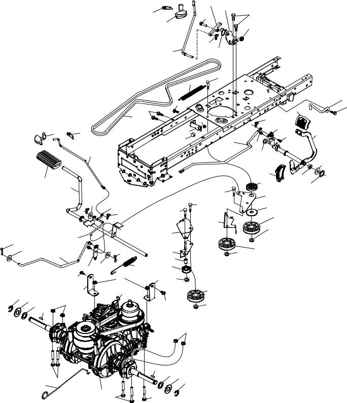
DRIVE
42
306
15
33 37
205
2
99
|
|
207 |
206 |
221 |
|
|
|
|
92 |
125 |
|
|
213 |
|
|
|
|
376 |
|
|
|
|
|
|
|
160 |
26 |
|
209 |
|
|
|
|
|
|
|
345 |
|
|
|
|
143 |
|
|
|
214 |
|
56 |
|
51 |
|
160 |
|
|
|
|
|
|
184 |
|
195 |
|
|
377 |
221 |
|
|
210 |
||
|
|
6 |
|
163 |
278 |
|
|
|
125 |
||
|
|
|
|
||
|
|
|
|
|
|
|
35 |
|
|
|
211 |
|
|
|
|
|
222
|
|
|
|
|
|
|
|
|
215 |
211 |
|
|
|
|
|
|
|
|
|
|
|
64 |
|
|
|
|
|
|
|
|
186 |
166 |
|
|
|
|
|
|
|
|
|
||
|
|
|
|
|
|
|
|
|
|
|
|
|
|
|
|
|
|
49 |
|
189 |
|
|
|
|
|
|
|
|
|
|
|
|
203 |
167 |
|
|
|
303 |
|
|
187 |
|
|
160 |
|
|
|
5 |
|
|
|
|
||
|
160 |
|
|
|
|
|
50 |
|
||
|
|
|
|
|
|
|
|
|
||
|
|
|
|
|
|
|
190 |
|
|
|
|
|
|
|
299 |
|
|
|
|
51 |
|
188 |
|
|
|
|
|
|
|
|
|
|
|
|
|
|
|
|
|
|
|
|
|
|
|
159 |
|
300 |
|
|
|
51 |
52 |
|
29 |
|
|
|
|
|
|
|
|||
|
|
373 |
|
|
|
|
|
|
||
|
|
|
|
|
|
|
|
|
||
125 |
|
|
|
|
|
|
|
|
|
|
67 |
|
|
|
|
|
|
|
|
|
|
374 |
17 |
|
302 |
|
|
|
|
|
|
|
|
|
|
|
|
|
|
|
|
|
|
125 |
|
116 |
172 |
375 |
|
|
|
|
|
|
172 |
|
378 |
|
|
|
|
301 |
|
|
|
|
|
|
|
|
|
|
|
|
|
|
116 |
|
|
|
125 |
|
|
51 |
|
|
|
|
|
|
|
|
|
|
|
|
||
|
|
|
|
|
|
116 |
|
|
|
|
2 |
|
205 |
37 |
73 |
33 |
|
1 |
282 |
|
73 |
drive-tex_VATR_PEDAL_36 |
|
|
|
197 196
8
TRACTOR - MODEL NO. YTA1946 (96048005500), PRODUCT NO. 960 48 00-55
DRIVE
KEY |
PART |
|
KEY |
PART |
|
NO. |
NO. |
DESCRIPTION |
NO. |
NO. |
DESCRIPTION |
1 |
– – – – – – |
Transmission, Variator SD Pdeal |
188 |
532 19 43-23 Link Clutch Ground Drive |
|
|
|
(584973901) (Order parts from |
189 |
532 19 43-17 Bellcrank Groundrive Nstg/Nstl |
|
|
|
transaxle manufacturer.) |
190 |
532 19 43-18 Keeper Bellcrank Drive Ground |
|
2 |
532 12 35-83 |
Key Square |
195 |
581 50 46-01 |
Brake Bracket |
5 |
874 76 06-36 |
Bolt Hex HS 3/8-16 unc |
196 |
817 00 06-16 Screw 3/8-16 x 1 |
|
6 |
532 12 40-28 |
Bushing Snap |
197 |
532 19 58-04 Link Clutch Anti-Rotation |
|
15 |
819 13 13-16 |
Washer 13/32 x 13/16 x 16 Ga. |
203 |
819 11 11-16 Washer 11/32 x 11/16 x 16 Ga. |
|
17 |
584 95 40-01 |
Spring Brake |
205 |
532 12 17-48 Washer 25/32 x 1-5/8 x 16 Ga. |
|
26 |
532 19 96-79 |
Spring Return Cruise |
206 |
532 44 85-96 Bracket Mount Latch Cruise |
|
29 |
584 82 31-01 |
Rod Brake |
207 |
532 44 82-64 Latch Control Cruise |
|
33 |
812 00 00-01 |
E-Ring |
209 |
532 19 95-92 Rod Control Cruise |
|
35 |
583 86 45-01 |
Rod Brake Parking |
210 |
532 44 82-70 Weldment Pedal |
|
37 |
532 18 89-67 |
Washer Harden .793 x 1.637 x 060 |
211 |
532 12 01-83 |
Bearing Nylon |
42 |
532 12 48-72 |
Cover Pedal Blk Round |
213 |
532 40 31-19 Knob Control Cruise |
|
49 |
872 11 06-14 |
Bolt Rdhd 3/8-16unc x1-3/4 Gr.5 |
214 |
532 42 12-63 Pedal Forward Pad |
|
50 |
532 19 43-27 |
Idler.Flat |
215 |
532 44 82-54 Cap Pedal Reverse |
|
51 |
873 90 06-00 |
Nut Hex Flangelock 3/8-16 |
221 |
532 40 31-87 Retainer Spring Clip Handle |
|
52 |
532 19 43-26 |
Idler V-Groove Offset |
222 |
879 21 20-10 Washer 21/32 x 1-1/4 10 Ga. |
|
56 |
532 19 72-53 |
Belt Drive |
278 |
580 36 91-01 Bolt Cruise Variator |
|
64 |
532 44 83-53 |
Shaft Asm. Pedal Brake |
282 |
874 49 05-48 Screw Thdrol 5/16-18 x 3 |
|
67 |
819 13 13-12 |
Washer 13/32 x 13/16 x 12 Ga. |
299 |
532 41 56-83 Bracket Mount Idler |
|
73 |
874 49 05-44 |
Bolt Hex Flghd 5/16-18 Gr. 5 |
300 |
532 41 56-81 Keeper Idler Rear |
|
92 |
874 76 05-20 |
Bolt |
301 |
532 41 56-80 Pulley Idler V-Groove |
|
99 |
532 43 59-35 |
Rod Bypass |
302 |
581 42 05-01 Pulley Idler Flat 2.0 Od |
|
116 |
873 90 05-00 |
Nut Lock Hex Flange 5/16-18 unc |
303 |
872 11 06-18 Bolt Rdhd Sgnk 3/8-16 x 2-1/4 |
|
125 |
817 00 05-12 |
Screw 5/16-18 x 3/4 Smgml Tap/Bl |
306 |
876 02 04-16 |
Cotter Pin |
143 |
817 49 05-08 |
Screw Thdrol 5/16-18 x 1/2 Tytt |
345 |
872 11 06-06 Bolt Rdhd Sgnk 3/8-16 x 1 Gr. 5 |
|
159 |
876 02 04-12 |
Pin Cotter 1/8 x 3/4 |
373 |
581 46 18-01 |
Spacer Idler |
160 |
532 16 94-84 |
Retainer Clip(M) Dia. 290 |
374 |
581 47 52-01 Bracket Brake Arm |
|
161 |
532 10 57-09 |
Spring Return Clutch 6.75 |
375 |
873 68 06-00 Nut Crownlock 3/8-16 unc |
|
163 |
583 97 13-01 |
Rod Control Pedal |
376 |
532 42 65-89 |
Nut Flange |
166 |
532 42 91-64 |
Nut Push .625 |
377 |
584 30 34-01 |
Gear Sector |
167 |
532 40 52-57 |
Latch Brake Parking |
378 |
584 28 77-01 |
Nut Push 8 mm |
172 |
583 97 42-01 |
Strap Torque LH/RH |
|
|
|
184 |
532 44 14-55 |
Handle Parking Brake |
|
|
|
185 |
872 11 06-22 |
Bolt Rdhd 3/8-16 unc x 2-3/4 Gr.5 |
NOTE: All component dimensions given in U.S. inches |
||
186 |
532 19 43-21 |
Spacer Retainer |
|||
187 |
819 13 32-10 |
Washer 13/32 x 2 x 10 Ga. |
|
1 inch = 25.4 mm |
|
9
TRACTOR - MODEL NO. YTA1946 (96048005500), PRODUCT NO. 960 48 00-55
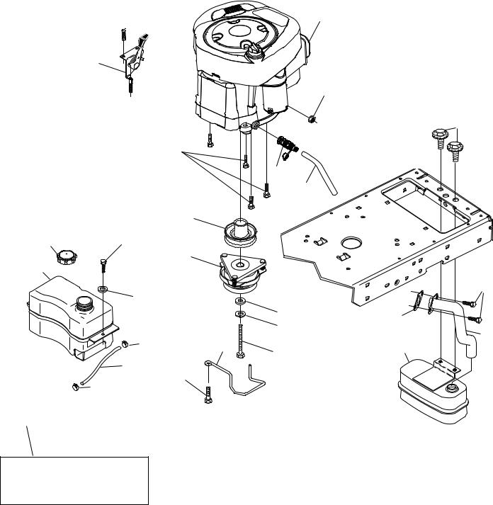
ENGINE
1
21

20
45
87
84
82
81
12
18 |
97 |
11
15
|
96 |
|
|
79 |
|
|
|
|
|
|
|
|
41 |
69 |
|
|
|
42 |
|
|
|
|
94 |
|
|
37 |
|
|
|
|
9 |
85 |
2 |
|
|
|
|||
|
28 |
|
|
|
|
90 |
|
|
|
37 |
|
|
|
|
|
|
|
|
29
OPTIONAL EQUIPMENT
Spark Arrester
engine-tex_BS_89
10
TRACTOR - MODEL NO. YTA1946 (96048005500), PRODUCT NO. 960 48 00-55
ENGINE
KEY |
PART |
|
NO. |
NO. |
DESCRIPTION |
1 |
– – – – – – |
Engine B&S Model No. 33S877- |
|
|
0009-G1 (586190501) (Order parts |
|
|
from engine manufacturer.) |
2 |
532 44 67-60 |
Muffler |
9 |
532 19 43-19 Keeper Belt Engine |
|
11 |
532 40 00-08 |
Clutch Electric |
12 |
532 40 29-80 |
Pulley Engine |
15 |
581 29 01-01 |
Tank Fuel |
18 |
532 43 02-20 |
Cap Asm |
20 |
532 40 15-08 |
Control Throttle |
21 |
532 41 63-58 Screw # 10 x 0.750 |
|
28 |
532 13 70-40 |
Fuel Line |
29 |
532 13 71-80 Spark Arrester Kit |
|
37 |
532 12 34-87 |
Clamp Hose |
41532 12 61-97 Washer 1-1/2 OD x 15/32 ID x .250
42810 04 07-00 Washer Lock 7/16
45 |
873 51 04-00 Nut Keps Hex 1/4-20 unc |
|
69 |
532 16 52-91 |
Gasket |
79 |
532 19 23-34 |
Screw Socket Hd. 5/16-18 x .75 |
81 |
532 14 84-56 |
Easy Oil Drain Tube |
82 |
532 42 82-87 |
Oil Drain Valve |
84817 06 06-20 Screw 3/8-16 x 1-1/4
85532 17 39-37 Bolt Hex 7/16-20 x 4 x Gr. 5-1.5 Thr
87 |
537 17 18-77 |
Bolt 5/16-18 unc x 3/4 w/Sems |
90 |
817 00 06-16 |
Screw 3/8-16 x 1 |
94 |
581 88 09-01 |
Tube Exhaust |
96819 09 14-16 Washer 9/32 x 7/8 x 16 Ga.
97817 67 04-12 Screw Hexwsh Thdrol 1/4-20 x 3/4
NOTE: All component dimensions given in U.S. inches 1 inch = 25.4 mm
For engine service and replacement parts, call the toll free number for your engine manufacturer listed below:
Briggs & Stratton |
1-800-233-3723 |
Engine Power Rating Information
The gross power rating for individual gas engine models is labeled in accordance with SAE (Society of Automotive Engineers) code J1940 (Small Engine Power & Torque Rating Procedure), and rating performance has been obtained and corrected in accordance with SAE J1995 (Revision 2002-05). Torque values are derived at 3060 RPM; horsepower values are derived at 3600 RPM. Actual gross engine power will be lower and is affected by, among other things, ambient operating conditions and engine-to-engine variability. Given both the wide array of products on which engines are placed and the variety of environmental issues applicable to operating the equipment, the gas engine will not develop the rated gross power when used in a given piece of power equipment (actual “on-site” or net power). This difference is due to a variety of factors including, but not limited to, accessories (air cleaner, exhaust, charging, cooling, carburetor, fuel pump, etc.), application limitations, ambient operating conditions (temperature, humidity, altitude), and engine-to-engine variability. Due to manufacturing and capacity limitations, Briggs & Stratton may substitute an engine of higher rated power for this Series engine.
11
 Loading...