


J Class
Owner's Guide
Workstation Systems Group
HP Part No. A4476±90013
Edition E0596
Printed in U.S.A.
Hewlett-Packard Co. 1995
First Printing: |
January 1995 |
Latest Printing: |
May 1996 |
UNIX is a registered trademark in the United States and other countries, licensed exclusively through X/Open Company Limited.
NOTICE
The information contained in this document is subject to change without notice.
HEWLETT-PACKARD MAKES NO WARRANTY OF ANY KIND WITH REGARD TO THIS MATERIAL INCLUDING BUT NOT LIMITED TO THE IMPLIED WARRANTIES OF MERCHANTABILITY AND FITNESS FOR A PARTICULAR PURPOSE. Hewlett-Packard shall not be liable for errors contained herein or for incidental or consequential damages in connection with the furnishing, performance or use of this material.
Hewlett-Packard assumes no responsibility for the use or reliability of its software on equipment that is not furnished by Hewlett-Packard.
This document contains proprietary information that is protected by copyright. All rights reserved. No part of this document may be photocopied, reproduced or translated to another language without the prior written consent of Hewlett-Packard Company.
RESTRICTED RIGHTS LEGEND. Use, duplication, or disclosure by government is subject to restrictions as set forth in subdivision (c) (1) (ii) of the Rights in Technical Data and Computer Software Clause at DFARS 252.227.7013. Hewlett-Packard Co., 3000 Hanover St., Palo Alto, CA 94304.
10 9 8 7 6 5 4 3 2 1
Preface
xiii
This owner's guide describes how to use your HP 9000 J Class workstation.
This manual assumes that you have installed your workstation as described in the J Class Hardware Installation Guide.
xiv

Audience |
This guide is intended for HP 9000 J Class workstation users. |
Safety and
Regulatory
Statements
See Appendix A in the back of this manual for safety and regulatory statements that apply to this workstation.
Release
Document(s)
Please refer to the Release Document(s) you received with your system or system software for additional information that we may not have been able to include in this guide at the time of its publication.
Related
Manuals
If you are using HP-UX version 9.05, refer to the following manuals for more information:
•
•
•
•
J Class Hardware Installation Guide (A4081±90600)
Using Your HP Workstation (A2615±90001)
Installing and Updating HP-UX (B2355±90039)
System Administration Tasks HP 9000 Series 700 Computers
(B2355±90040)
•
•
•
Installing Peripherals (B2355±90041)
HP Visual User Environment User's Guide (B1171±90061)
Managing Clusters of HP 9000 Computers: Sharing the HP-UX
File System (B2355±90038)
• Using HP-UX (B2910±90001)
To order manuals, please contact your local sales office.
xv

If you are using HP-UX version 10.0, refer to the following manuals for more information:
•
•
•
•
J Class Hardware Installation Guide (A4081±90600)
Using Your HP Workstation (A2615±90003)
Installing and Updating HP-UX (B2355±90050)
System Administration Tasks HP 9000 Series 700 Computers
(B2355±90051)
•Configuring HP-UX for Peripherals
(B2355±90053)
•
•
HP Visual User Environment User's Guide (B1171±90079)
Managing Clusters of HP 9000 Computers: Sharing the HP-UX File System (B2355±90038)
To order manuals, please contact your local sales office.
Revision History |
The revision history for each edition of the manual is listed below: |
||
|
HP Part No. |
Edition |
Revision History |
|
A4081±90601 |
E0195 |
First printing |
|
A4081±90607 |
E0695 |
Second printing |
|
A4476±90013 |
E0596 |
Latest printing |
xvi
Documentation
Conventions
Unless otherwise noted in the text, this guide uses the following symbolic conventions.
literal values |
Bold words or characters in formats and command de- |
|
scriptions represent commands or key words that you |
|
must use literally. Pathnames are also in bold. |
user-supplied |
Italic words or characters in formats and command |
values |
descriptions represent values that you must supply. |
sample user |
In examples, information that the user enters appears |
input |
in color. |
output |
Information that the system displays appears in |
|
this typeface. |
Enter |
A colored rectangle with rounded corners and a key |
|
label denotes a key on your keyboard. (In this manual |
|
we refer to the Enter key. On your keyboard the key |
|
may be labeled either Enter or Return.) |
Screen Button
This colored symbol with a label in it denotes an HP VUE screen button. A screen button is a key or button which is drawn on your workstation's graphic display by HP VUE. It works like a keyboard key, except that you must move the mouse cursor over it and press the left mouse button to activate it. The screen button's label describes its function.
This symbol indicates a notice.
This symbol indicates a procedure.
This symbol indicates a caution.
This symbol indicates the end of a chapter or a part of this guide.
xvii

Questions, Suggestions, or Problems
If you have any questions, suggestions, or problems with our hardware, software, or documentation, please call 1±888±301±5932 ( US & Canada ) or contact the HP Response Center for your country.
xviii

Contents
Preface
Chapter 1 |
System Overview |
|
|
Product Description . . . . . . . . . . . . . . . . . . . . . . . . . . . . . . . . . . . |
. 1-3 |
|
System Unit Front Panel Controls, LED, and LCD . . . . . . . . . . . . |
1-6 |
|
System LCD . . . . . . . . . . . . . . . . . . . . . . . . . . . . . . . . . . . . . . . |
1-7 |
|
System Power Switch . . . . . . . . . . . . . . . . . . . . . . . . . . . . . . . . |
1-7 |
|
System Power LED . . . . . . . . . . . . . . . . . . . . . . . . . . . . . . . . . |
1-8 |
|
Removable Device Buttons and LEDs . . . . . . . . . . . . . . . . . . . |
1-8 |
|
System Unit Rear Panel Connectors . . . . . . . . . . . . . . . . . . . . . . . |
1-10 |
|
Audio Connectors . . . . . . . . . . . . . . . . . . . . . . . . . . . . . . . . . . |
1-12 |
|
Keyboard Connectors . . . . . . . . . . . . . . . . . . . . . . . . . . . . . . . |
1-14 |
|
HP Parallel I/O Connector . . . . . . . . . . . . . . . . . . . . . . . . . . . |
1-15 |
|
802.3 Network Connectors . . . . . . . . . . . . . . . . . . . . . . . . . . . |
1-15 |
|
RS-232C Serial Input/Output Connector . . . . . . . . . . . . . . . . |
1-15 |
|
SCSI Connectors . . . . . . . . . . . . . . . . . . . . . . . . . . . . . . . . . . |
1-16 |
|
Power Cord Connector . . . . . . . . . . . . . . . . . . . . . . . . . . . . . . |
1-16 |
|
Monitors . . . . . . . . . . . . . . . . . . . . . . . . . . . . . . . . . . . . . . . . . . . . |
1-17 |
|
Keyboards . . . . . . . . . . . . . . . . . . . . . . . . . . . . . . . . . . . . . . . . . . . |
1-18 |
|
Keyboard Differences . . . . . . . . . . . . . . . . . . . . . . . . . . . . . . |
1-18 |
|
Pointing Devices . . . . . . . . . . . . . . . . . . . . . . . . . . . . . . . . . . . . . . |
1-21 |
|
Operating System Overview . . . . . . . . . . . . . . . . . . . . . . . . . . . . . |
1-22 |
|
Important Information You Need to Note . . . . . . . . . . . . . . . . . . . |
1-23 |
|
LANIC ID . . . . . . . . . . . . . . . . . . . . . . . . . . . . . . . . . . . . . . . |
1-23 |
|
SCSI ID and Device File Information for HP-UX 9.05 . . . . . |
1-25 |
|
SCSI ID and Device File Information for HP-UX 10.0 |
|
|
or Later . . . . . . . . . . . . . . . . . . . . . . . . . . . . . . . . . . . . . . . . . |
1-25 |
iii
|
IP Address and Subnetwork Mask Information . . . . . . . . . . . |
1-26 |
|
|
Networking Overview . . . . . . . . . . . . . . . . . . . . . . . . . . . . . . . . . |
1-27 |
|
|
Mail . . . . . . . . . . . . . . . . . . . . . . . . . . . . . . . . . . . . . . . . . . . . |
1-27 |
|
|
telnet . . . . . . . . . . . . . . . . . . . . . . . . . . . . . . . . . . . . . . . . . . . . |
1-27 |
|
|
rlogin . . . . . . . . . . . . . . . . . . . . . . . . . . . . . . . . . . . . . . . . . . . |
1-27 |
|
|
ftp . . . . . . . . . . . . . . . . . . . . . . . . . . . . . . . . . . . . . . . . . . . . . . |
1-28 |
|
|
rcp . . . . . . . . . . . . . . . . . . . . . . . . . . . . . . . . . . . . . . . . . . . . . . |
1-28 |
|
|
NFS . . . . . . . . . . . . . . . . . . . . . . . . . . . . . . . . . . . . . . . . . . . . |
1-28 |
|
|
|
|
|
Chapter 2 |
Setting Up Your Printer |
|
|
|
Gathering Printer Information . . . . . . . . . . . . . . . . . . . . . . . . . . . |
. 2-3 |
|
|
Setting Up a Local Printer Using SAM . . . . . . . . . . . . . . . . . . . . . |
2-4 |
|
|
Setting Up Your Printer for Network Printing . . . . . . . . . . . . . . . |
2-10 |
|
|
Printing a File . . . . . . . . . . . . . . . . . . . . . . . . . . . . . . . . . . . . . . . . |
2-12 |
|
|
Solving Printing Problems . . . . . . . . . . . . . . . . . . . . . . . . . . . . . . |
2-13 |
|
|
|
|
|
Chapter 3 |
Using Your CD±ROM Drive |
|
|
|
CD-ROM Drive and CD-ROM Media Descriptions . . . . . . . . . . . |
3-3 |
|
|
CD-ROM Drive . . . . . . . . . . . . . . . . . . . . . . . . . . . . . . . . . . . . |
3-3 |
|
|
Controls and Features . . . . . . . . . . . . . . . . . . . . . . . . . . . . |
3-3 |
|
|
CD-ROM Media . . . . . . . . . . . . . . . . . . . . . . . . . . . . . . . . . . . . |
3-5 |
|
|
Caring for CD-ROM Discs . . . . . . . . . . . . . . . . . . . . . . . . |
3-5 |
|
|
Operating the CD-ROM Drive . . . . . . . . . . . . . . . . . . . . . . . . . . . . |
3-6 |
|
|
Loading and Unloading a CD-ROM Disc . . . . . . . . . . . . . . . . |
3-6 |
|
|
Loading a CD-ROM Disc . . . . . . . . . . . . . . . . . . . . . . . . . |
3-6 |
|
|
Unloading a CD-ROM Disc . . . . . . . . . . . . . . . . . . . . . . . |
3-9 |
|
|
Verifying the CD-ROM Drive Operation . . . . . . . . . . . . . . . . |
3-11 |
|
|
Using Device Files . . . . . . . . . . . . . . . . . . . . . . . . . . . . . . . . . |
3-14 |
|
|
Mounting and Unmounting a CD-ROM Disc . . . . . . . . . . . . . . . |
3-15 |
|
|
Mounting a CD-ROM Disc Using SAM . . . . . . . . . . . . . . . . |
3-15 |
|
|
Unmounting a CD-ROM Disc Using SAM . . . . . . . . . . . . . . |
3-18 |
|
|
Reading the Busy Light . . . . . . . . . . . . . . . . . . . . . . . . . . . . . |
3-21 |
|
|
Troubleshooting . . . . . . . . . . . . . . . . . . . . . . . . . . . . . . . . . . . |
3-22 |
|
iv
Chapter 4 |
Using Your DDS Tape Drive |
|
|
DDS Tape Drive and Data Cassette Descriptions . . . . . . . . . . . . |
. . 4-3 |
|
DDS Drive . . . . . . . . . . . . . . . . . . . . . . . . . . . . . . . . . . . . . . |
. . 4-3 |
|
Controls and Indicators . . . . . . . . . . . . . . . . . . . . . . . . . |
. . 4-3 |
|
LEDs ± DDS-DC Drive . . . . . . . . . . . . . . . . . . . . . . . . . |
. . 4-4 |
|
LED Warning Conditions ± DDS-DC Drive . . . . . . . . . |
. . 4-5 |
|
LEDs ± DDS-2 . . . . . . . . . . . . . . . . . . . . . . . . . . . . . . . . |
. . 4-6 |
|
Data Cassettes . . . . . . . . . . . . . . . . . . . . . . . . . . . . . . . . . . . |
. . 4-7 |
|
Media Life . . . . . . . . . . . . . . . . . . . . . . . . . . . . . . . . . . . |
. . 4-7 |
|
Cleaning the Tape Heads . . . . . . . . . . . . . . . . . . . . . . . . |
. . 4-7 |
|
Media Restrictions . . . . . . . . . . . . . . . . . . . . . . . . . . . . . |
. . 4-8 |
|
Setting the Write-Protect Tab on a Data Cassette . . . . . . . . |
. . 4-8 |
|
Operating the DDS Tape Drive . . . . . . . . . . . . . . . . . . . . . . . . . . |
. . 4-9 |
|
Loading and Unloading a Data Cassette . . . . . . . . . . . . . . . |
. . 4-9 |
|
Verifying the DDS Tape Drive Operation . . . . . . . . . . . . . . |
. 4-10 |
|
Using Device Files . . . . . . . . . . . . . . . . . . . . . . . . . . . . . . . . |
. 4-12 |
|
Archiving Data in Compressed and Noncompressed Mode |
. 4-13 |
|
Writing to a Data Cassette . . . . . . . . . . . . . . . . . . . . . . . . . . |
. 4-14 |
|
Restoring Files from a Data Cassette to Your System . . . . . |
. 4-15 |
|
Listing the Files on a Data Cassette . . . . . . . . . . . . . . . . . . . |
. 4-16 |
|
Further Command Information . . . . . . . . . . . . . . . . . . . . . . |
. 4-17 |
|
Media Interchangeability Restrictions . . . . . . . . . . . . . . . . . |
. 4-17 |
|
Troubleshooting . . . . . . . . . . . . . . . . . . . . . . . . . . . . . . . . . . |
. 4-17 |
|
Ordering Information . . . . . . . . . . . . . . . . . . . . . . . . . . . . . . |
. 4-18 |
Chapter 5 |
Using Your 3.5±Inch Floppy Drive |
|
|
Using the Floppy Diskette . . . . . . . . . . . . . . . . . . . . . . . . . . . . . . . |
5-3 |
|
Setting the Write-Protect Tab on a Diskette . . . . . . . . . . . . . . . |
5-3 |
|
Inserting and Removing a Diskette . . . . . . . . . . . . . . . . . . . . . |
5-4 |
|
Operating the Floppy Drive . . . . . . . . . . . . . . . . . . . . . . . . . . . . . . |
5-5 |
|
Verifying the Floppy Drive Configuration . . . . . . . . . . . . . . . . |
5-5 |
|
Using Device Files . . . . . . . . . . . . . . . . . . . . . . . . . . . . . . . . . . |
5-7 |
|
Formatting a New Diskette . . . . . . . . . . . . . . . . . . . . . . . . . . . |
5-8 |
|
Transferring Data To and From a Floppy Diskette . . . . . . . . . |
5-8 |
|
Saving Files to a Floppy Diskette . . . . . . . . . . . . . . . . . . . . . . |
5-9 |
v

Restoring Files from a Floppy Diskette to Your System . . . . . 5-9
Listing the Files on a Floppy Diskette . . . . . . . . . . . . . . . . . . 5-10
For More Information . . . . . . . . . . . . . . . . . . . . . . . . . . . . . . 5-11
Configuring the Floppy Driver . . . . . . . . . . . . . . . . . . . . . . . 5-12
Troubleshooting . . . . . . . . . . . . . . . . . . . . . . . . . . . . . . . . . . . 5-12
Ordering Information . . . . . . . . . . . . . . . . . . . . . . . . . . . . . . . 5-12
Chapter 6 |
Solving Problems |
|
|
Common Problems and Solutions . . . . . . . . . . . . . . . . . . . . . . . . |
. 6-3 |
|
Dealing with a Boot Failure . . . . . . . . . . . . . . . . . . . . . . . . . . . . . |
6-10 |
|
Memory Failures . . . . . . . . . . . . . . . . . . . . . . . . . . . . . . . . . . . . . . |
6-11 |
|
LCD-Indicated Problems . . . . . . . . . . . . . . . . . . . . . . . . . . . . . . . |
6-12 |
|
Running System Verification Tests . . . . . . . . . . . . . . . . . . . . . . . . |
6-15 |
Appendix A |
Safety and Regulatory Statements |
|
|
Declaration of Conformity . . . . . . . . . . . . . . . . . . . . . . . . . . . . . . |
A-2 |
|
Federal Communications Commission (FCC) . . . . . . . . . . . . . . . |
A-3 |
|
Emissions Regulations . . . . . . . . . . . . . . . . . . . . . . . . . . . . . . . . . |
A-3 |
|
VCCI Class 1 ITE . . . . . . . . . . . . . . . . . . . . . . . . . . . . . . . . . |
A-4 |
|
Emissions Regulations Compliance . . . . . . . . . . . . . . . . . . . . . . . |
A-4 |
|
Datacom Users Statement (United Kingdom Only) . . . . . . . . . . . |
A-4 |
|
Regulation On Noise Declaration For Machines ±3. GSGV . A-4 |
|
|
Acoustics . . . . . . . . . . . . . . . . . . . . . . . . . . . . . . . . . . . . . . . . . . . . |
A-4 |
|
Electrostatic Discharge (ESD) Precautions . . . . . . . . . . . . . . . . . |
A-4 |
|
Laser Safety Statement (For U.S.A. Only) . . . . . . . . . . . . . . . . . . |
A-5 |
|
IEC 825 Class 1 Laser Label . . . . . . . . . . . . . . . . . . . . . . . . . . . . |
A-5 |
|
Warnings and Cautions . . . . . . . . . . . . . . . . . . . . . . . . . . . . . . . . . |
A-6 |
Appendix B |
Changing Your Workstation's Hardware |
|
|
Configuration |
|
|
Checking the SCSI IDs . . . . . . . . . . . . . . . . . . . . . . . . . . . . . . . . . |
B-3 |
|
Opening the System Unit . . . . . . . . . . . . . . . . . . . . . . . . . . . . . . . |
B-6 |
|
Closing the System Unit . . . . . . . . . . . . . . . . . . . . . . . . . . . . . . . . |
B-8 |
|
Installing Removable Media Devices . . . . . . . . . . . . . . . . . . . . . |
B-10 |
vi
|
CD-ROM Drive . . . . . . . . . . . . . . . . . . . . . . . . . . . . . . . . . . |
B-14 |
|
|
DDS Tape Drive . . . . . . . . . . . . . . . . . . . . . . . . . . . . . . . . . . |
B-16 |
|
|
Floppy Drive . . . . . . . . . . . . . . . . . . . . . . . . . . . . . . . . . . . . |
B-20 |
|
|
Adding a Hard Drive . . . . . . . . . . . . . . . . . . . . . . . . . . . . . . . . . |
B-27 |
|
|
Installing a Hard Disk Drive . . . . . . . . . . . . . . . . . . . . . . . . |
B-30 |
|
|
Configuring a Hard Drive . . . . . . . . . . . . . . . . . . . . . . . . . . |
B-33 |
|
|
Installing Additional Memory . . . . . . . . . . . . . . . . . . . . . . . . . . |
B-36 |
|
|
Adding a Second Processor . . . . . . . . . . . . . . . . . . . . . . . . . . . . |
B-44 |
|
|
Installing an EISA or Graphics Board . . . . . . . . . . . . . . . . . . . . |
B-50 |
|
|
Changing Your Monitor Type . . . . . . . . . . . . . . . . . . . . . . . . . . . |
B-60 |
|
|
Setting the Monitor Type from the Boot Console Interface . B-60 |
||
|
Setting the Monitor Type at Power On . . . . . . . . . . . . . . . . |
B-60 |
|
|
|
|
|
Appendix C |
SCSI Connections |
|
|
|
SCSI Bus Differences . . . . . . . . . . . . . . . . . . . . . . . . . . . . . . . . . . |
C-3 |
|
|
SCSIRestrictions . . . . . . . . . . . . . . . . . . . . . . . . . . . . . . . . . . . . . . |
C-5 |
|
|
Cables . . . . . . . . . . . . . . . . . . . . . . . . . . . . . . . . . . . . . . . . . . . |
C-5 |
|
|
Connectors and Terminator . . . . . . . . . . . . . . . . . . . . . . . . . . |
C-7 |
|
|
SCSI Configuration Constraints . . . . . . . . . . . . . . . . . . . . . . . |
C-7 |
|
|
Single-Ended SCSI-2 Bus Configuration Constraints . . . . . . |
C-7 |
|
|
Fast, Wide SCSI-3 Bus Configuration Constraints . . . . . . . . |
C-9 |
|
|
Determining SCSI Bus Length . . . . . . . . . . . . . . . . . . . . . . . . . . . |
C-9 |
|
|
Single-Ended SCSI-2 Bus Length . . . . . . . . . . . . . . . . . . . . . |
C-9 |
|
|
Fast, Wide SCSI-3 Bus Length . . . . . . . . . . . . . . . . . . . . . . |
C-12 |
|
|
Assigning SCSIDevice IDs . . . . . . . . . . . . . . . . . . . . . . . . . . . . . |
C-14 |
|
|
Single-Ended Standard System SCSI Device IDs . . . . . . . . |
C-16 |
|
|
Fast, Wide SCSI IDs . . . . . . . . . . . . . . . . . . . . . . . . . . . . . . |
C-20 |
|
|
Connecting to the SCSI Ports . . . . . . . . . . . . . . . . . . . . . . . . . . . |
C-21 |
|
|
System SCSI Port Connection . . . . . . . . . . . . . . . . . . . . . . . |
C-21 |
|
|
|
|
|
Appendix D |
The Boot Console Interface |
|
|
|
Boot Console Interface Features . . . . . . . . . . . . . . . . . . . . . . . . . . |
D-3 |
|
|
Accessing the Boot Console Interface . . . . . . . . . . . . . . . . . . . . . |
D-8 |
|
|
Booting Your Workstation . . . . . . . . . . . . . . . . . . . . . . . . . . . . . . |
D-9 |
|
|
Searching for Bootable Media . . . . . . . . . . . . . . . . . . . . . . . . . . |
D-11 |
|
|
Resetting Your Workstation . . . . . . . . . . . . . . . . . . . . . . . . . . . . |
D-12 |
|
vii

Displaying and Setting Paths . . . . . . . . . . . . . . . . . . . . . . . . . . . D-12
Displaying and Setting the Monitor Type . . . . . . . . . . . . . . . . . . D-14
The Monitor Command . . . . . . . . . . . . . . . . . . . . . . . . . . . . D-14
Displaying the Current Monitor Configuration . . . . . . . . . . D-15
Setting the Monitor Type . . . . . . . . . . . . . . . . . . . . . . . . . . . D-16
Displaying the Current Memory Configuration . . . . . . . . . . . . . D-19
Sample Output 1 . . . . . . . . . . . . . . . . . . . . . . . . . . . . . . . . . . D-19
Sample Output 2 . . . . . . . . . . . . . . . . . . . . . . . . . . . . . . . . . . D-20
Displaying the Status of the EISA Slots . . . . . . . . . . . . . . . . . . . D-22
Setting the Auto Boot and Auto Search Flags . . . . . . . . . . . . . . D-23
Displaying and Setting the Fastboot Mode . . . . . . . . . . . . . . . . . D-24
Displaying the LAN Station Address . . . . . . . . . . . . . . . . . . . . . D-24
Displaying System Information . . . . . . . . . . . . . . . . . . . . . . . . . D-25
Displaying PIM Information . . . . . . . . . . . . . . . . . . . . . . . . . . . D-25
Glossary
Index
viii

Figures
1±1. |
System Unit Front Panel Controls . . . . . . . . . . . . . . . . . |
. . . 1-6 |
1±2. |
LCD Symbols . . . . . . . . . . . . . . . . . . . . . . . . . . . . . . . . . |
. . . 1-7 |
1±3. |
System Unit with Removable Device Door Open . . . . . |
. . . 1-9 |
1±4. |
System Unit Rear Panel Connectors . . . . . . . . . . . . . . . |
. . 1-11 |
1±5. |
Audio Connectors . . . . . . . . . . . . . . . . . . . . . . . . . . . . . . |
. . 1-12 |
3±1. |
CD-ROM Drive Controls and Features . . . . . . . . . . . . . |
. . . 3-3 |
3±2. |
CD-ROM Disc Tray Partway Open . . . . . . . . . . . . . . . . |
. . . 3-6 |
3±3. |
Placing the CD-ROM Disc in the Disc Tray . . . . . . . . . |
. . . 3-7 |
3±4. |
Disc Tray Closed . . . . . . . . . . . . . . . . . . . . . . . . . . . . . . |
. . . 3-8 |
3±5. |
CD-ROM Disc Tray Partway Open . . . . . . . . . . . . . . . . |
. . . 3-9 |
3±6. |
Removing the CD-ROM Disc From the Disc Tray . . . . |
. . 3-10 |
3±7. |
Disc Tray Closed . . . . . . . . . . . . . . . . . . . . . . . . . . . . . . |
. . 3-11 |
4±1. |
DDS Drive Controls and Indicators . . . . . . . . . . . . . . . . |
. . . 4-3 |
4±2. |
Setting the Write-Protect Tab on a DDS Tape . . . . . . . . |
. . . 4-8 |
4±3. |
Loading a Data Cassette . . . . . . . . . . . . . . . . . . . . . . . . . |
. . . 4-9 |
5±1. |
Setting the Write-Protect Tab on a Floppy Diskette . . . . |
. . . 5-3 |
5±2. |
Inserting and Removing a Floppy Diskette . . . . . . . . . . |
. . . 5-4 |
B±1. |
Removing the Front Panel . . . . . . . . . . . . . . . . . . . . . . . |
. . B-7 |
B±2. |
Replacing the Front Panel . . . . . . . . . . . . . . . . . . . . . . . |
. . B-9 |
B±3. |
Removing Storage Drawer from System Unit . . . . . . . . |
. B-11 |
B±4. |
Removing EMI Plate . . . . . . . . . . . . . . . . . . . . . . . . . . . |
. B-12 |
B±5. |
Removing Drive Screws . . . . . . . . . . . . . . . . . . . . . . . . |
. B-13 |
B±6. |
CD-ROM Drive SCSI Address/Jumper Settings . . . . . . |
. B-15 |
B±7. |
DDS-DC Tape Drive SCSI Address/Jumper Settings . . . B-17 |
|
B±8. |
DDS-2 Tape Drive and SCSI Address/Jumper Settings |
. B-18 |
B±9. |
Switch Settings for Data Compression Operation Mode . B-19 |
|
B±10. Floppy Drive SCSI Address/Jumper Settings . . . . . . . . |
. B-21 |
|
B±11. Floppy Drive Terminators . . . . . . . . . . . . . . . . . . . . . . . |
. B-22 |
|
B±12. Attaching Removable Drive Mounting Bracket |
|
|
and Drive Orientation . . . . . . . . . . . . . . . . . . . . . . . . . . . . . . . |
. B-23 |
|
B±13. Replacing Drive Screws . . . . . . . . . . . . . . . . . . . . . . . . . |
. B-24 |
|
B±14. Replacing the Storage Drawer Assembly . . . . . . . . . . . |
. B-25 |
|
ix
B±15. Fast, Wide Hard Drive Jumper Settings . . . . . . . . . . . . . . |
B-28 |
|
B±16. Replacing Hard Drive Mounting Bracket |
|
|
and Drive Orientation . . . . . . . . . . . . . . . . . . . . . . . . . . . . . . . . |
B-29 |
|
B±17. Removing Storage Drawer from System Unit . . . . . . . . . |
B-31 |
|
B±18. Placing Hard Drives in Storage Drawer . . . . . . . . . . . . . . |
B-32 |
|
B±19. Removing the CPU Assembly . . . . . . . . . . . . . . . . . . . . . |
B-37 |
|
B±20. Memory SIMM Location . . . . . . . . . . . . . . . . . . . . . . . . . |
B-38 |
|
B±21. CPU Assembly Orientation . . . . . . . . . . . . . . . . . . . . . . . |
B-39 |
|
B±22. Memory SIMM Sequence . . . . . . . . . . . . . . . . . . . . . . . . |
B-40 |
|
B±23. Installing Memory Cards . . . . . . . . . . . . . . . . . . . . . . . . . |
B-41 |
|
B±24. Replacing the CPU Assembly . . . . . . . . . . . . . . . . . . . . . |
B-42 |
|
B±25. Removing the CPU Assembly . . . . . . . . . . . . . . . . . . . . . |
B-44 |
|
B±26. CPU Shroud Location . . . . . . . . . . . . . . . . . . . . . . . . . . . |
B-45 |
|
B±27. Removing CPU Shroud and Disconnecting Fan Cable . . |
B-46 |
|
B±28. Removing CPU and Connector Dust Covers . . . . . . . . . . |
B-47 |
|
B±29. Replacing the CPU Assembly . . . . . . . . . . . . . . . . . . . . . |
B-48 |
|
B±30. EISA/GSC Slots from Outside the EISA Assembly . . . . |
B-50 |
|
B±31. EISA/GSC Slots from Inside the EISA Assembly . . . . . . |
B-51 |
|
B±32. Removing the EISA Assembly . . . . . . . . . . . . . . . . . . . . |
B-52 |
|
B±33. Rotating the EISA Assembly for Installation . . . . . . . . . . |
B-53 |
|
B±34. Removing the EISA Assembly Cover . . . . . . . . . . . . . . . |
B-54 |
|
B±35. Removing the EISA Slot Cover . . . . . . . . . . . . . . . . . . . . |
B-55 |
|
B±36. Installing an EISA or Graphics Board in the EISA |
|
|
Assembly . . . . . . . . . . . . . . . . . . . . . . . . . . . . . . . . . . . . . . . . . |
B-56 |
|
B±37. Replacing EISA Assembly Cover . . . . . . . . . . . . . . . . . . |
B-57 |
|
B±38. Rotating the EISA Assembly Back . . . . . . . . . . . . . . . . . |
B-58 |
|
B±39. Replacing EISA Assembly . . . . . . . . . . . . . . . . . . . . . . . . |
B-59 |
|
C±1. |
Rear Panel SCSI Connectors with Terminators Attached |
C-22 |
C±2. |
Rear Panel SCSI Connectors without Terminators . . . . . |
C-23 |
x

Tables
1±1. |
Audio Electrical Specifications . . . . . . . . . . . . . . . . . . |
. . . 1-14 |
1±2. |
Serial I/O Pins . . . . . . . . . . . . . . . . . . . . . . . . . . . . . . . |
. . . 1-16 |
1±3. |
PS/2 Keyboard to ITF Keyboard Equivalent Keys . . . |
. . . 1-19 |
3±1. |
CD-ROM Drive Operating Controls and Features . . . . |
. . . . 3-4 |
4±1. |
LED Display Codes ± DDS-DC Drive . . . . . . . . . . . . . |
. . . . 4-4 |
4±2. |
LED Display Codes ± DDS-2 Drive . . . . . . . . . . . . . . |
. . . . 4-6 |
6±1. |
Problems Powering Up the System . . . . . . . . . . . . . . . |
. . . . 6-3 |
6±2. |
Problems Loading and Booting the Operating System |
. . . . 6-4 |
6±3. |
Problems with the 802.3 Network . . . . . . . . . . . . . . . . |
. . . . 6-5 |
6±4. |
Problems Using a Hard Disk Drive . . . . . . . . . . . . . . . |
. . . . 6-6 |
6±5. |
Problems Using the CD-ROM Drive . . . . . . . . . . . . . . |
. . . . 6-7 |
6±6. |
Problems Using the DDS Tape Drive . . . . . . . . . . . . . |
. . . . 6-8 |
6±7. |
Problems Using the Floppy Disk Drive . . . . . . . . . . . . |
. . . . 6-9 |
C±1. |
SCSI Bus Differences . . . . . . . . . . . . . . . . . . . . . . . . . . |
. . . C-3 |
C±2. SCSI Bus Addresses, ID Numbers, |
|
|
and Arbitration Priorities . . . . . . . . . . . . . . . . . . . . . . . . . . . |
. . . C-4 |
|
C±3. |
Single-Ended SCSI-2 Bus Configuration Constraints . . . . C-8 |
|
C±4. |
Fast, Wide SCSI-3 Bus Configuration Constraints . . . |
. . . C-9 |
C±5. |
SCSI-2 Bus Length Worksheet for Single-Ended |
|
Standard SCSI-2 Bus . . . . . . . . . . . . . . . . . . . . . . . . . . . . . . |
. . C-11 |
|
C±6. |
SCSI-3 Bus Length Worksheet for Fast, Wide |
|
SCSI-3 Bus . . . . . . . . . . . . . . . . . . . . . . . . . . . . . . . . . . . . . . |
. . C-13 |
|
C±7. Single-Ended SCSI Device IDs . . . . . . . . . . . . . . . . . . |
. . C-18 |
|
C±8. Fast, Wide SCSI Device IDs . . . . . . . . . . . . . . . . . . . . |
. . C-20 |
|
D±1. System Paths . . . . . . . . . . . . . . . . . . . . . . . . . . . . . . . . . . D-12
D±2. Mnemonic Style Notation . . . . . . . . . . . . . . . . . . . . . . . . D-13
xi
xii

Chapter 1
System Overview
•Product description
•System unit front panel controls, LED, and LCD
•System unit rear panel connectors
•Monitors
•Keyboards
•Pointing devices
•Operating system overview
•Important information you need to note
•Networking overview
1-1
This chapter introduces the HP 9000 J Class workstation. Its purpose is to familiarize you with your workstation and its controls and indicators.
The instructions in this chapter assume you are using the HP-UX version 9.05 or later operating system with the HP VUE version 3.0 interface.
1-2
Product
Description
This workstation has the following key features:
• Operating System |
HP-UX version 9.05 or later |
• User Interface |
HP VUE version 3.0 graphical user |
|
interface |
•
•
Compatibility |
Source and binary code compatible |
|
with the Series 700 product family |
Monitors |
17-inch 1280x1024 color monitor |
|
or |
|
20-inch 1280x1024 color monitor |
• Optional Graphics |
2D color graphics (single and dual |
|
head) |
|
HCRX-8/HCRX-24 fast 8-plane or |
|
24-plane graphics |
|
HCRX-8Z/HCRX-24Z accelerated |
|
8-plane or 24-plane graphics |
|
CRX-48Z 24-plane accelerated, |
|
double-buffered graphics |
|
Freedom series 3150 graphics sub- |
|
system w/1 MB texture memory |
|
Freedom series 3250 graphics sub- |
|
system w/1 MB texture memory |
|
Freedom series 3400 graphics sub- |
|
system w/1 MB texture memory |
• Main Memory |
32 MB to 768 MB for systems running |
|
HP-UX 9.05 |
|
32 MB to 1 GB (1024 MB) for systems |
|
running HP-UX 10.0 or later |
|
1-3 |
• Internal Storage Devices
Fast, wide SCSI hard disk drives ± up to two:
1.0 GB Drive
2.0 GB Drive Single-Ended SCSI removable
Media ± up to two: CD-ROM Drive
2.0±8.0 GB, 4-mm DDS tape drive
Floppy drive
• Standard Network |
Ethernet IEEE 802.3 AUI Thicknet |
|
or |
|
RJ45, UTP Twisted Pair |
• Standard I/O |
One SCSI-2: Single-Ended, |
|
8-bit (for removable devices) |
|
5 MB/sec synchronous |
|
1.5 MB/sec asynchronous |
|
ALT-1, 50-pin, high density |
|
SCSI-2 connector |
|
One SCSI-3: Fast, wide (for hard disk |
|
drives) |
|
20 MB/sec synchronous |
|
68-pin, high-density SCSI-3 |
|
P connector |
|
Two serial interfaces |
|
RS-232C, 9-pin male |
|
One parallel interface |
|
Centronics, BUSY handshake |
|
25-pin female |
1-4
• EISA/GSC |
Five slots total; four EISA and |
|
three GSC that can be used as |
|
follows: two individual EISA, one |
|
individual GSC, and two |
|
combination EISA or GSC. |
• Keyboards |
PS/2 Keyboard |
|
or |
|
ITF Keyboard (also known as |
|
HP HIL) |
1-5

System Unit
Front Panel
Controls, LED,
and LCD
Before powering on your system, you should become familiar with the system unit controls.
Figure 1±1 shows the the system unit front panel controls.


 e
e


 e o e h
e o e
Figure 1±1. System Unit Front Panel Controls
1-6

System LCD
The Liquid Crystal Display (LCD) is located on the left side of the front panel. It displays messages about the state of the system, including error codes. The following symbols appear in the LCD, representing the different system activities shown:
Operating system running
Disk Access in progress
Network Receive in progress
Network Transmit in progress
Figure 1±2. LCD Symbols
System Power Switch
Use the Power switch to power the system unit on and off.
CAUTION: Do not turn off the power to your workstation without first performing the recommended shutdown procedure. If you do not shut down your workstation properly, you can damage the programs and data on your disk.
Using the proper shutdown method for your workstation and operating system also ensures that your system produces the proper diagnostic and self test messages, and broadcasts a warning message to remote terminals that it is about to shutdown.
1-7

If you are using HP-UX 9.05, the recommended method of shutting down your workstation is using the software command /etc/shutdown.
If you are using HP-UX 10.0 or later, follow the instructions in Using Your HP Workstation to shut down your workstation.
System Power LED
The Power Light Emitting Diode (LED) is located on the left side of the front panel. It lights when the system unit power is on and flashes until the OS is booted. Once the OS is booted, the LED remains on without flashing.
Removable Device Buttons and LEDs
Depending on your configuration, you can have up to two (2) of the following removable device drives:
•
•
•
CD-ROM disc drive
DDS tape drive
Floppy diskette drive
NOTICE: You cannot have two of the same type of device. For example, you can have a CD-ROM device and a floppy device, but not two CDROMs.
A description of each drive's controls and indicators is in the chapter describing that device, later in this book.
Figure 1±3 shows the system unit with the removable device door open. A removable device is in the top bay; a blank covers the empty bottom bay.
1-8
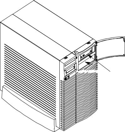


 Removable Device
Bays (2)
Figure 1±3. System Unit with Removable Device Door Open
1-9

System Unit
Rear Panel
Connectors
1-10
This section describes the following connectors on the system unit's rear panel:
•Audio connectors (including headphones and microphone)
•PS/2 keyboard and mouse connectors
•HP parallel Centronics I/O connector
•802.3 AUI LAN connector
•802.3 TP (Twisted Pair) LAN connector
•RS-232C serial I/O connectors
•HP HIL keyboard connector
•SCSI connectors (including fast, wide SCSI-3 and single-ended SCSI-2
•TOC button
•Power cord connector
NOTICE: To maintain FCC/EMI compliance, verify that all cables are fully seated and properly fastened.
Figure 1±4 shows the locations of the connectors on the system unit's rear panel.

Fast, Wide SCSI43 |
Audio |
|
Connectors** |
||
Connector* |
||
|
||
Singled4Ended |
|
|
SCSI42 Connector* |
|
|
TOC |
|
|
Button |
|
|
(not shown) |
|
|
|
Mouse |
|
|
Connector |
*SCSI Connectors are shown with terminators attached, as they are shipped from the factory.
**See Figure 1-5 for detail on Audio Connectors.
Power
Connector
Graphics
Connector
Keyboard
Connector
Parallel I/O
Connector
AUI LAN
Connector
Twisted Pair
Connector
(labeled UTP)
RS4232C
Connectors
HP HIL
Connector
Figure 1±4. System Unit Rear Panel Connectors
1-11

The symbols shown to the left of the connector descriptions in the following text, such as the headphone and microphone for audio connectors, are the same symbols used on the rear panel of the J Class workstation.
Audio Connectors
Your workstation has audio input and output capability through external input and output connectors on the rear panel and through an internal speaker. The rear panel contains the Audio IN (stereo line-in), Mic (microphone-in), Audio OUT (stereo line-out), and Headphones (headphones-out) connectors.
Headphones OUT |
Mic IN |
Connector |
Connector |
Audio IN |
Audio OUT |
Connector |
Connector |
Figure 1±5. Audio Connectors
The audio connectors are standard stereo audio mini-jacks. HewlettPackard recommends using gold-plated plugs available through audio retailers for best quality recording and playback through the external connectors. A summary of the workstation audio features follows.
1-12
 Loading...