


 Loading...
service handbook
hp workstation c-class
Manufacturing Part Number: n/a
Printed in USA October 2001
Edition E1001

notice
The information contained in this document is subject to change without notice.
Hewlett-Packard assumes no responsibility for the use or reliability of its software on equipment that is not furnished by Hewlett-Packard.
This document contains proprietary information that is protected by copyright. All rights reserved. No part of this document may be photocopied, reproduced or translated to another language without the prior written consent of Hewlett-Packard Company.
hewlett-packard warranty statement
HP PRODUCT |
DURATION OF WARRANTY |
HP Workstations C-Class |
one Year |
1.HP warrants HP hardware, accessories and supplies against defects in materials and workmanship for the period specified above. If HP receives notice of such defects during the warranty period, HP will, at its option, either repair or replace products which prove to be defective. Replacement products may be either new or like-new.
2.HP warrants that HP software will not fail to execute its programming instructions, for the period specified above, due to defects in material and workmanship when properly installed and used. If HP receives notice of such defects during the warranty period, HP will replace software media which does not execute its programming instructions due to such defects.
3.HP does not warrant that the operation of HP products will be uninterrupted or error free. If HP is unable, within a reasonable time, to repair or replace any product to a condition as warranted, the customer will be entitled to a refund of the purchase price upon prompt return of the product.
4.HP products may contain remanufactured parts equivalent to new in performance or may have been subject to incidental use.
5.The warranty period begins on the date of delivery or on the date of installation if installed by HP. If customer schedules installation or causes installation by HP to be delayed more than 30 days after delivery, warranty begins on the 31st day from delivery.
6.Warranty does not apply to defects resulting from (a) improper or inadequate maintenance or calibration, (b) software, interfacing, parts or supplies not supplied by HP, (c) unauthorized modification or misuse, (d) operation outside of the published
2

environmental specifications for the product, or (e) improper site preparation or maintenance.
7.TO THE EXTENT ALLOWED BY LOCAL LAW, THE ABOVE WARRANTIES ARE EXCLUSIVE AND NO OTHER WARRANTY OR CONDITION, WHETHER WRITTEN OR ORAL, IS EXPRESSED OR IMPLIED AND HP SPECIFICALLY DISCLAIMS ANY IMPLIED WARRANTIES OR CONDITIONS OF MERCHANTABILITY, SATISFACTORY QUALITY, AND FITNESS FOR A PARTICULAR PURPOSE.
8.HP will be liable for damage to tangible property per incident up to the greater of $300,000 or the actual amount paid for the product that is the subject of the claim, and for damages for bodily injury or death, to the extent that all such damages are determined by a court of competent jurisdiction to have been directly caused by a defective HP product.
9.TO THE EXTENT ALLOWED BY LOCAL LAW, THE REMEDIES IN THIS WARRANTY STATEMENT ARE CUSTOMER’S SOLE AND EXCLUSIVE REMEDIES. EXCEPT AS INDICATED ABOVE, IN NO EVENT WILL HP OR ITS SUPPLIERS BE LIABLE FOR LOSS OF DATA OR FOR DIRECT, SPECIAL, INCIDENTAL, CONSEQUENTIAL (INCLUDING LOST PROFIT OR DATA), OR OTHER DAMAGE, WHETHER BASED IN CONTRACT, TORT, OR OTHERWISE.
FOR CONSUMER TRANSACTIONS IN AUSTRALIA AND NEW ZEALAND: THE WARRANTY TERMS CONTAINED IN THIS STATEMENT, EXCEPT TO THE EXTENT LAWFULLY PERMITTED, DO NOT EXCLUDE, RESTRICT OR MODIFY AND ARE IN ADDITION TO THE MANDATORY STATUTORY RIGHTS APPLICABLE TO THE SALE OF THIS PRODUCT TO YOU.
restricted rights legend
Use, duplication, or disclosure by the U.S. Government Department of Defense is subject to restrictions as set forth in paragraph (b)(3)(ii) of the Rights in Technical Data and Software clause in DFARS 252.227.7013.
© Copyright 1999 Hewlett-Packard Company. All Rights Reserved.
This document contains proprietary information that is protected by copyright. All rights are reserved. No part of this document may be photocopied, reproduced or translated to another language without the prior written consent of Hewlett-Packard Company.
UNIX is a registered trademark in the United States and other countries, licensed exclusively through X/Open Company Limited.
©Copyright 1980, 1984 AT&T, Inc.
©Copyright 1979, 1980, 1983 The Regents of the University of California.
This software and documentation is based in part on the Fourth Berkeley Software Distribution under license from the Regents of University of California.
3

printing history
New editions of this manual incorporate all material updated since the previous edition. Update packages may be issued between editions and contain replacement and additional pages to be merged into the manual by the user.
The manual part number and printing date indicate its current edition. The manual part number changes when extensive technical changes are incorporated. The printing date changes when a new edition is printed. (Minor corrections and updates which are incorporated at reprint do not cause the date to change.)
HP Part Number |
Printing Date |
Edition |
n/a |
October 2001 |
First |
4

Contents
1. product information
Product Description . . . . . . . . . . . . . . . . . . . . . . . . . . . . . . . . . . . . . . . . . .19 system unit front panel controls . . . . . . . . . . . . . . . . . . . . . . . . . . . . . . . .21 system LCD. . . . . . . . . . . . . . . . . . . . . . . . . . . . . . . . . . . . . . . . . . . . . . .21 system power switch. . . . . . . . . . . . . . . . . . . . . . . . . . . . . . . . . . . . . . . .22 storage device controls and features . . . . . . . . . . . . . . . . . . . . . . . . . . .22 security lock . . . . . . . . . . . . . . . . . . . . . . . . . . . . . . . . . . . . . . . . . . . . . .24 System Unit Rear Panel Connectors . . . . . . . . . . . . . . . . . . . . . . . . . . . .25 audio connectors . . . . . . . . . . . . . . . . . . . . . . . . . . . . . . . . . . . . . . . . . . .26 USB connectors. . . . . . . . . . . . . . . . . . . . . . . . . . . . . . . . . . . . . . . . . . . .27 hp parallel i/o connector . . . . . . . . . . . . . . . . . . . . . . . . . . . . . . . . . . . . .27 802.3 network connectors. . . . . . . . . . . . . . . . . . . . . . . . . . . . . . . . . . . .27 RS-232 serial input/output connectors . . . . . . . . . . . . . . . . . . . . . . . . .28 SCSI connectors . . . . . . . . . . . . . . . . . . . . . . . . . . . . . . . . . . . . . . . . . . .28 TOC button . . . . . . . . . . . . . . . . . . . . . . . . . . . . . . . . . . . . . . . . . . . . . . .29 power cord connector . . . . . . . . . . . . . . . . . . . . . . . . . . . . . . . . . . . . . . .29 security loop . . . . . . . . . . . . . . . . . . . . . . . . . . . . . . . . . . . . . . . . . . . . . .29 monitor information . . . . . . . . . . . . . . . . . . . . . . . . . . . . . . . . . . . . . . . . .31 hp supported USB devices . . . . . . . . . . . . . . . . . . . . . . . . . . . . . . . . . . . .32 USB keyboard. . . . . . . . . . . . . . . . . . . . . . . . . . . . . . . . . . . . . . . . . . . . .32 USB hp scroll mouse . . . . . . . . . . . . . . . . . . . . . . . . . . . . . . . . . . . . . . .32 hp hub for USB devices . . . . . . . . . . . . . . . . . . . . . . . . . . . . . . . . . . . . .32 operating system overview . . . . . . . . . . . . . . . . . . . . . . . . . . . . . . . . . . . .33 memory. . . . . . . . . . . . . . . . . . . . . . . . . . . . . . . . . . . . . . . . . . . . . . . . . . . .34 memory failures . . . . . . . . . . . . . . . . . . . . . . . . . . . . . . . . . . . . . . . . . . .34
2. configuration
chapter overview . . . . . . . . . . . . . . . . . . . . . . . . . . . . . . . . . . . . . . . . . . . .36 workstation configurations . . . . . . . . . . . . . . . . . . . . . . . . . . . . . . . . . . . .37 FRU configurations . . . . . . . . . . . . . . . . . . . . . . . . . . . . . . . . . . . . . . . . . .38 internal storage configurations . . . . . . . . . . . . . . . . . . . . . . . . . . . . . . .38 CD drive (optional) configuration . . . . . . . . . . . . . . . . . . . . . . . . . . . . .42
5

Contents
floppy disk drive (optional) configuration . . . . . . . . . . . . . . . . . . . . . . 42 memory . . . . . . . . . . . . . . . . . . . . . . . . . . . . . . . . . . . . . . . . . . . . . . . . . 43 i/o cards . . . . . . . . . . . . . . . . . . . . . . . . . . . . . . . . . . . . . . . . . . . . . . . . . 45 monitor-type selection. . . . . . . . . . . . . . . . . . . . . . . . . . . . . . . . . . . . . . 46
3. troubleshooting
flow diagrams for troubleshooting. . . . . . . . . . . . . . . . . . . . . . . . . . . . . . 49 identifying LCD-indicated conditions . . . . . . . . . . . . . . . . . . . . . . . . . . . 54 LCD fan failures and warnings . . . . . . . . . . . . . . . . . . . . . . . . . . . . . . . . 55 dealing with a boot failure . . . . . . . . . . . . . . . . . . . . . . . . . . . . . . . . . . . . 57 searching for bootable media . . . . . . . . . . . . . . . . . . . . . . . . . . . . . . . . 58 stable storage . . . . . . . . . . . . . . . . . . . . . . . . . . . . . . . . . . . . . . . . . . . . 58 boot command notations . . . . . . . . . . . . . . . . . . . . . . . . . . . . . . . . . . . . 59 supported boot paths. . . . . . . . . . . . . . . . . . . . . . . . . . . . . . . . . . . . . . . 59 ISL environment . . . . . . . . . . . . . . . . . . . . . . . . . . . . . . . . . . . . . . . . . . 59 selftest failures . . . . . . . . . . . . . . . . . . . . . . . . . . . . . . . . . . . . . . . . . . . . 60 chassis codes . . . . . . . . . . . . . . . . . . . . . . . . . . . . . . . . . . . . . . . . . . . . . 61 memory failures . . . . . . . . . . . . . . . . . . . . . . . . . . . . . . . . . . . . . . . . . . 83 running system verification tests . . . . . . . . . . . . . . . . . . . . . . . . . . . . . . 84 running ODE-based diagnostics . . . . . . . . . . . . . . . . . . . . . . . . . . . . . . . 86
4. field replaceable units
exchange and non-exchange part numbers. . . . . . . . . . . . . . . . . . . . . . . 93 FRUs part numbers . . . . . . . . . . . . . . . . . . . . . . . . . . . . . . . . . . . . . . . 94
. . . . . . . . . . . . . . . . . . . . . . . . . . . . . . . . . . . . . . . . . . . . . . . . . . . . . . . . 95 FRU removal and replacement . . . . . . . . . . . . . . . . . . . . . . . . . . . . . . . . 97 system unit front panel. . . . . . . . . . . . . . . . . . . . . . . . . . . . . . . . . . . . . 98 system power supply. . . . . . . . . . . . . . . . . . . . . . . . . . . . . . . . . . . . . . 102 i/o cards . . . . . . . . . . . . . . . . . . . . . . . . . . . . . . . . . . . . . . . . . . . . . . . . 106 system unit fans . . . . . . . . . . . . . . . . . . . . . . . . . . . . . . . . . . . . . . . . . 109 removable media devices . . . . . . . . . . . . . . . . . . . . . . . . . . . . . . . . . . 117 hard disk drive . . . . . . . . . . . . . . . . . . . . . . . . . . . . . . . . . . . . . . . . . . 134
6

Contents
DIMM cards . . . . . . . . . . . . . . . . . . . . . . . . . . . . . . . . . . . . . . . . . . . . .141 system unit LCD. . . . . . . . . . . . . . . . . . . . . . . . . . . . . . . . . . . . . . . . . .145 the system board . . . . . . . . . . . . . . . . . . . . . . . . . . . . . . . . . . . . . . . . .147 replacing the battery . . . . . . . . . . . . . . . . . . . . . . . . . . . . . . . . . . . . . .150
5. diagrams
system power . . . . . . . . . . . . . . . . . . . . . . . . . . . . . . . . . . . . . . . . . . . . . .152 system unit block diagram . . . . . . . . . . . . . . . . . . . . . . . . . . . . . . . . . . .153
6. boot console handler
boot console handler features . . . . . . . . . . . . . . . . . . . . . . . . . . . . . . . . .157 accessing the boot console handler . . . . . . . . . . . . . . . . . . . . . . . . . . . . .158 boot console menus . . . . . . . . . . . . . . . . . . . . . . . . . . . . . . . . . . . . . . . . .159 booting the workstation. . . . . . . . . . . . . . . . . . . . . . . . . . . . . . . . . . . . . .164 searching for bootable media . . . . . . . . . . . . . . . . . . . . . . . . . . . . . . . . .166 resetting the workstation . . . . . . . . . . . . . . . . . . . . . . . . . . . . . . . . . . . .167 displaying and setting paths. . . . . . . . . . . . . . . . . . . . . . . . . . . . . . . . . .168 displaying and setting the monitor type. . . . . . . . . . . . . . . . . . . . . . . . .170
the monitor command . . . . . . . . . . . . . . . . . . . . . . . . . . . . . . . . . . . . .170 displaying the current monitor configuration. . . . . . . . . . . . . . . . . . .171 setting the monitor type. . . . . . . . . . . . . . . . . . . . . . . . . . . . . . . . . . . .172 setting the monitor type at power on . . . . . . . . . . . . . . . . . . . . . . . . .173 troubleshooting monitor problems. . . . . . . . . . . . . . . . . . . . . . . . . . . .174
displaying the current memory configuration . . . . . . . . . . . . . . . . . . . .175 memory information sample . . . . . . . . . . . . . . . . . . . . . . . . . . . . . . . .176 displaying the status of the i/o slots . . . . . . . . . . . . . . . . . . . . . . . . . . . .177 setting the auto boot and auto search flags . . . . . . . . . . . . . . . . . . . . . .178 displaying and setting the security mode. . . . . . . . . . . . . . . . . . . . . . . .179 displaying and setting fastboot mode . . . . . . . . . . . . . . . . . . . . . . . . . . .180 displaying and setting the LAN station address . . . . . . . . . . . . . . . . . .181 displaying system information . . . . . . . . . . . . . . . . . . . . . . . . . . . . . . . .182 displaying pim information . . . . . . . . . . . . . . . . . . . . . . . . . . . . . . . . . . .183
7

Contents
stable storage . . . . . . . . . . . . . . . . . . . . . . . . . . . . . . . . . . . . . . . . . . . . . 184 ISL environment . . . . . . . . . . . . . . . . . . . . . . . . . . . . . . . . . . . . . . . . . . 185 invoking ISL from the boot console handler . . . . . . . . . . . . . . . . . . . 185 ISL user commands. . . . . . . . . . . . . . . . . . . . . . . . . . . . . . . . . . . . . . . 185 obtaining and updating system firmware . . . . . . . . . . . . . . . . . . . . . . . 187 to install the firmware update . . . . . . . . . . . . . . . . . . . . . . . . . . . . . . 187 firmware update example . . . . . . . . . . . . . . . . . . . . . . . . . . . . . . . . . . 188
A. product specifications
regulatory and safety statements . . . . . . . . . . . . . . . . . . . . . . . . . . . . . 192 emissions regulations . . . . . . . . . . . . . . . . . . . . . . . . . . . . . . . . . . . . . 194 special video configuration statement . . . . . . . . . . . . . . . . . . . . . . . . 194 emissions regulations compliance . . . . . . . . . . . . . . . . . . . . . . . . . . . 195 acoustics. . . . . . . . . . . . . . . . . . . . . . . . . . . . . . . . . . . . . . . . . . . . . . . . 196 laser safety statement (U.S.A.). . . . . . . . . . . . . . . . . . . . . . . . . . . . . . 196 LEDs . . . . . . . . . . . . . . . . . . . . . . . . . . . . . . . . . . . . . . . . . . . . . . . . . . 196 electrostatic discharge (ESD) precautions. . . . . . . . . . . . . . . . . . . . . 196 warnings . . . . . . . . . . . . . . . . . . . . . . . . . . . . . . . . . . . . . . . . . . . . . . . 197
environmental specifications . . . . . . . . . . . . . . . . . . . . . . . . . . . . . . . . . 198 acoustics . . . . . . . . . . . . . . . . . . . . . . . . . . . . . . . . . . . . . . . . . . . . . . . 198 altitude . . . . . . . . . . . . . . . . . . . . . . . . . . . . . . . . . . . . . . . . . . . . . . . . 198 DC magnetic field interference. . . . . . . . . . . . . . . . . . . . . . . . . . . . . . 198 electromagnetic compatibility (EMC) . . . . . . . . . . . . . . . . . . . . . . . . 198 temperature. . . . . . . . . . . . . . . . . . . . . . . . . . . . . . . . . . . . . . . . . . . . . 198 humidity (non-condensing) . . . . . . . . . . . . . . . . . . . . . . . . . . . . . . . . . 198 leakage current . . . . . . . . . . . . . . . . . . . . . . . . . . . . . . . . . . . . . . . . . . 198 shock . . . . . . . . . . . . . . . . . . . . . . . . . . . . . . . . . . . . . . . . . . . . . . . . . . 198 vibration . . . . . . . . . . . . . . . . . . . . . . . . . . . . . . . . . . . . . . . . . . . . . . . 199
electrical specifications . . . . . . . . . . . . . . . . . . . . . . . . . . . . . . . . . . . . . 200 input power . . . . . . . . . . . . . . . . . . . . . . . . . . . . . . . . . . . . . . . . 200 line power . . . . . . . . . . . . . . . . . . . . . . . . . . . . . . . . . . . . . . . . . . . . . . 200
8

Contents
B. SCSI connections
SCSI Bus Differences . . . . . . . . . . . . . . . . . . . . . . . . . . . . . . . . . . . . . . .203 SCSI restrictions . . . . . . . . . . . . . . . . . . . . . . . . . . . . . . . . . . . . . . . . . . .204 cables. . . . . . . . . . . . . . . . . . . . . . . . . . . . . . . . . . . . . . . . . . . . . . . . . . .204 terminators . . . . . . . . . . . . . . . . . . . . . . . . . . . . . . . . . . . . . . . . . . . . . .206 number of devices per SCSI bus . . . . . . . . . . . . . . . . . . . . . . . . . . . . .206 considerations for selecting SCSI devices . . . . . . . . . . . . . . . . . . . . . .206 SCSI bus length constraints . . . . . . . . . . . . . . . . . . . . . . . . . . . . . . . . . .208 Ultra narrow single-ended SCSI bus length. . . . . . . . . . . . . . . . . . . .208 Ultra2 wide low-voltage differential SCSI bus length . . . . . . . . . . . .208 assigning SCSI device IDs. . . . . . . . . . . . . . . . . . . . . . . . . . . . . . . . . . . .210 assigning Ultra narrow single-ended SCSI device IDs . . . . . . . . . . .211 assigning Ultra2 wide low-voltage differential SCSI device IDs. . . .211 connecting to the SCSI ports. . . . . . . . . . . . . . . . . . . . . . . . . . . . . . . . . .212 system SCSI port connection . . . . . . . . . . . . . . . . . . . . . . . . . . . . . . . .212
C. related documentation
. . . . . . . . . . . . . . . . . . . . . . . . . . . . . . . . . . . . . . . . . . . . . . . . . . . . . . . . .216 installation manual . . . . . . . . . . . . . . . . . . . . . . . . . . . . . . . . . . . . . . .216 service manuals . . . . . . . . . . . . . . . . . . . . . . . . . . . . . . . . . . . . . . . . . .216 reference manuals . . . . . . . . . . . . . . . . . . . . . . . . . . . . . . . . . . . . . . . .216
Glossary
9

Contents
10
Figures
Figure 1-1. System Unit Front Panel Controls . . . . . . . . . . . . . . . . . . . . . . . . . . . . . . . . . . 21 Figure 1-2. LCD Symbols . . . . . . . . . . . . . . . . . . . . . . . . . . . . . . . . . . . . . . . . . . . . . . . . . . . 22 Figure 1-3. CD Drive . . . . . . . . . . . . . . . . . . . . . . . . . . . . . . . . . . . . . . . . . . . . . . . . . . . . . . . 23 Figure 1-4. Floppy Drive Controls and Features . . . . . . . . . . . . . . . . . . . . . . . . . . . . . . . . . 24 Figure 1-5. System Unit Rear Panel Connectors. . . . . . . . . . . . . . . . . . . . . . . . . . . . . . . . . 25 Figure 1-6. Audio Connectors . . . . . . . . . . . . . . . . . . . . . . . . . . . . . . . . . . . . . . . . . . . . . . . . 26 Figure 1-7. Security Loop Operation . . . . . . . . . . . . . . . . . . . . . . . . . . . . . . . . . . . . . . . . . . 30 Figure 2-1. Hard Drive, 9Gbyte/18Gbyte Ultra2 Low Voltage Differential . . . . . . . . . . . . 39 Figure 2-2. CD Drive Jumper Setting (Rear View) . . . . . . . . . . . . . . . . . . . . . . . . . . . . . . . 42 Figure 2-3. Memory Connectors . . . . . . . . . . . . . . . . . . . . . . . . . . . . . . . . . . . . . . . . . . . . . . 43 Figure 2-4. PCI Card Slot Numbering and Capabilities . . . . . . . . . . . . . . . . . . . . . . . . . . . 45 Figure 3-1. Power On LCD, Troubleshooting Flow . . . . . . . . . . . . . . . . . . . . . . . . . . . . . . . 50 Figure 3-2. Console Troubleshooting Messages. . . . . . . . . . . . . . . . . . . . . . . . . . . . . . . . . . 51 Figure 3-3. Bootable Device Troubleshooting . . . . . . . . . . . . . . . . . . . . . . . . . . . . . . . . . . . 52 Figure 3-4. Troubleshooting HP-UX Boot . . . . . . . . . . . . . . . . . . . . . . . . . . . . . . . . . . . . . . 53 Figure 3-5. Fan Locations . . . . . . . . . . . . . . . . . . . . . . . . . . . . . . . . . . . . . . . . . . . . . . . . . . . 56 Figure 4-1. HP Workstation C-Class Main Components. . . . . . . . . . . . . . . . . . . . . . . . . . . 89 Figure 4-2. CD Drive Bracket Assembly . . . . . . . . . . . . . . . . . . . . . . . . . . . . . . . . . . . . . . . 90 Figure 4-3. Floppy Drive Bracket Assembly . . . . . . . . . . . . . . . . . . . . . . . . . . . . . . . . . . . . 91 Figure 4-4. Hard Disk Drive Bracket Assembly . . . . . . . . . . . . . . . . . . . . . . . . . . . . . . . . . 92 Figure 4-5. Opening the Front Bezel . . . . . . . . . . . . . . . . . . . . . . . . . . . . . . . . . . . . . . . . . . 98 Figure 4-6. Opening the Left Side Panel of the System Unit . . . . . . . . . . . . . . . . . . . . . . 100 Figure 4-7. Unscrewing the Power Supply Captive Screws . . . . . . . . . . . . . . . . . . . . . . . 102 Figure 4-8. Propping Up the Power Supply . . . . . . . . . . . . . . . . . . . . . . . . . . . . . . . . . . . . 103 Figure 4-9. Disconnecting the Power Supply Cables. . . . . . . . . . . . . . . . . . . . . . . . . . . . . 104 Figure 4-10. Removing the Power Supply . . . . . . . . . . . . . . . . . . . . . . . . . . . . . . . . . . . . . 105 Figure 4-11. PCI Card Slot Numbering and Capabilities . . . . . . . . . . . . . . . . . . . . . . . . . 106 Figure 4-12. I/O Slot Numbering . . . . . . . . . . . . . . . . . . . . . . . . . . . . . . . . . . . . . . . . . . . . 106 Figure 4-13. Removing the I/O Card Retainer. . . . . . . . . . . . . . . . . . . . . . . . . . . . . . . . . . 107 Figure 4-14. Removing the I/O Card . . . . . . . . . . . . . . . . . . . . . . . . . . . . . . . . . . . . . . . . . 107 Figure 4-15. Fan Cooling Areas for the System Unit . . . . . . . . . . . . . . . . . . . . . . . . . . . . 109 Figure 4-16. Removing the Fan from the Hard Disk Drive Chassis. . . . . . . . . . . . . . . . . 111 Figure 4-17. Removing the Fan Rivets. . . . . . . . . . . . . . . . . . . . . . . . . . . . . . . . . . . . . . . . 112 Figure 4-18. Removing CPU Area Fans . . . . . . . . . . . . . . . . . . . . . . . . . . . . . . . . . . . . . . . 113 Figure 4-19. Removing the System Unit Air Divider . . . . . . . . . . . . . . . . . . . . . . . . . . . . 114 Figure 4-20. Removing the Fan and Speaker from the I/O Area . . . . . . . . . . . . . . . . . . . 115 Figure 4-21. Removing the Fan and Speaker from the Bracket . . . . . . . . . . . . . . . . . . . . 115 Figure 4-22. Removing the CD Drive Rear Cover . . . . . . . . . . . . . . . . . . . . . . . . . . . . . . . 118 Figure 4-23. Front of System Unit with the Front Panel Removed . . . . . . . . . . . . . . . . . 118
11

Figures
Figure 4-24. Removing the CD Drive Bracket and Blank . . . . . . . . . . . . . . . . . . . . . . . . .119 Figure 4-25. Installing the CD Drive . . . . . . . . . . . . . . . . . . . . . . . . . . . . . . . . . . . . . . . . .120 Figure 4-26. Tightening the Bracket Screws . . . . . . . . . . . . . . . . . . . . . . . . . . . . . . . . . . .120 Figure 4-27. Plugging in the ATAPI and Power Cables . . . . . . . . . . . . . . . . . . . . . . . . . . .121 Figure 4-28. Replacing the Rear EMI CD Drive Cover . . . . . . . . . . . . . . . . . . . . . . . . . . .121 Figure 4-29. Removing the CD Drive’s Rear Cover . . . . . . . . . . . . . . . . . . . . . . . . . . . . . .122 Figure 4-30. Front of the System Unit with the Front Panel Removed . . . . . . . . . . . . . .122 Figure 4-31. Removing the CD Drive . . . . . . . . . . . . . . . . . . . . . . . . . . . . . . . . . . . . . . . . .123 Figure 4-32. Installing the CD Drive Blank . . . . . . . . . . . . . . . . . . . . . . . . . . . . . . . . . . . .124 Figure 4-33. Tightening the Bracket Screws . . . . . . . . . . . . . . . . . . . . . . . . . . . . . . . . . . .124 Figure 4-34. Replacing the CD Drive Rear Cover. . . . . . . . . . . . . . . . . . . . . . . . . . . . . . . .125 Figure 4-35. Removing the Floppy Disk’s Rear Cover . . . . . . . . . . . . . . . . . . . . . . . . . . . .126 Figure 4-36. Front of Workstation with the Front Panel Removed . . . . . . . . . . . . . . . . . .126 Figure 4-37. Removing the Floppy Disk Bracket and Blank . . . . . . . . . . . . . . . . . . . . . . .127 Figure 4-38. Installing the Floppy Disk Drive . . . . . . . . . . . . . . . . . . . . . . . . . . . . . . . . . .128 Figure 4-39. Tightening the Bracket Screws . . . . . . . . . . . . . . . . . . . . . . . . . . . . . . . . . . .128 Figure 4-40. Plugging in the Data and Power Cables . . . . . . . . . . . . . . . . . . . . . . . . . . . .129 Figure 4-41. Replacing the Rear Floppy Cover. . . . . . . . . . . . . . . . . . . . . . . . . . . . . . . . . .129 Figure 4-42. Removing the Floppy Disk’s Rear Cover . . . . . . . . . . . . . . . . . . . . . . . . . . . .130 Figure 4-43. Front of Workstation with the Front Panel Removed . . . . . . . . . . . . . . . . . .130 Figure 4-44. Removing the Floppy Disk Drive . . . . . . . . . . . . . . . . . . . . . . . . . . . . . . . . . .131 Figure 4-45. Installing the Floppy Disk Blank and Bracket . . . . . . . . . . . . . . . . . . . . . . .132 Figure 4-46. Tightening the Bracket Screws . . . . . . . . . . . . . . . . . . . . . . . . . . . . . . . . . . .132 Figure 4-47. Replacing the Rear Floppy Cover. . . . . . . . . . . . . . . . . . . . . . . . . . . . . . . . . .133 Figure 4-48. The Hard Drive Slots . . . . . . . . . . . . . . . . . . . . . . . . . . . . . . . . . . . . . . . . . . .135 Figure 4-49. Removing the Hard Drive Bracket. . . . . . . . . . . . . . . . . . . . . . . . . . . . . . . . .136 Figure 4-50. Inserting the Hard Disk Drive . . . . . . . . . . . . . . . . . . . . . . . . . . . . . . . . . . . .137 Figure 4-51. The Hard Drive Slots . . . . . . . . . . . . . . . . . . . . . . . . . . . . . . . . . . . . . . . . . . .138 Figure 4-52. Removing the Hard Disk Drive . . . . . . . . . . . . . . . . . . . . . . . . . . . . . . . . . . .138 Figure 4-53. Removing the Hard Disk Drive from the Bracket. . . . . . . . . . . . . . . . . . . . .139 Figure 4-54. Replacing the Hard Disk Drive Bracket . . . . . . . . . . . . . . . . . . . . . . . . . . . .140 Figure 4-55. Propping Up the Power Supply . . . . . . . . . . . . . . . . . . . . . . . . . . . . . . . . . . .141 Figure 4-56. DIMM Card Slot Numbers and Loading Sequence . . . . . . . . . . . . . . . . . . . .142 Figure 4-57. Installing Memory Cards . . . . . . . . . . . . . . . . . . . . . . . . . . . . . . . . . . . . . . . .143 Figure 4-58. Propping Up the Power Supply . . . . . . . . . . . . . . . . . . . . . . . . . . . . . . . . . . .144 Figure 4-59. Removing Memory Cards . . . . . . . . . . . . . . . . . . . . . . . . . . . . . . . . . . . . . . . .144 Figure 4-60. Removing the System Unit LCD . . . . . . . . . . . . . . . . . . . . . . . . . . . . . . . . . .145 Figure 4-61. Removing the System Board . . . . . . . . . . . . . . . . . . . . . . . . . . . . . . . . . . . . .148 Figure 4-62. Installing the System Board. . . . . . . . . . . . . . . . . . . . . . . . . . . . . . . . . . . . . .149
12

Figures
Figure 5-1. Power Distribution Diagram . . . . . . . . . . . . . . . . . . . . . . . . . . . . . . . . . . . . . . 152 Figure 5-2 System Unit Functional Block Diagram . . . . . . . . . . . . . . . . . . . . . . . . . . . . . 153 Figure A-1. VCCI Class B ITE (Japan) . . . . . . . . . . . . . . . . . . . . . . . . . . . . . . . . . . . . . . . 195 Figure A-2. RRL Class A EMI (Korea) . . . . . . . . . . . . . . . . . . . . . . . . . . . . . . . . . . . . . . . . 195 Figure A-3. EMI Class A (Taiwan) . . . . . . . . . . . . . . . . . . . . . . . . . . . . . . . . . . . . . . . . . . . 195 Figure B-1. SCSI Ports . . . . . . . . . . . . . . . . . . . . . . . . . . . . . . . . . . . . . . . . . . . . . . . . . . . . 212
13

Figures
14

Tables
Table 1-1. CD Drive Controls . . . . . . . . . . . . . . . . . . . . . . . . . . . . . . . . . . . . . . . . . . . . . . . . 23 Table 1-2. Floppy Drive Controls and Features. . . . . . . . . . . . . . . . . . . . . . . . . . . . . . . . . . 24 Table 1-3. Audio Electrical Specifications . . . . . . . . . . . . . . . . . . . . . . . . . . . . . . . . . . . . . . 27 Table 1-4. Serial I/O Pins . . . . . . . . . . . . . . . . . . . . . . . . . . . . . . . . . . . . . . . . . . . . . . . . . . . 28 Table 2-1. Default Device IDs TABLE . . . . . . . . . . . . . . . . . . . . . . . . . . . . . . . . . . . . . . . . . 38 Table 3-1. Fan Numbers and Corresponding Name . . . . . . . . . . . . . . . . . . . . . . . . . . . . . . 55 Table 3-2. Chassis Codes for th HP Workstation C-Class . . . . . . . . . . . . . . . . . . . . . . . . . . 61 Table 4-1. Exchange Parts FRU List . . . . . . . . . . . . . . . . . . . . . . . . . . . . . . . . . . . . . . . . . . 94 Table 4-2. Non-exchange Parts FRU List. . . . . . . . . . . . . . . . . . . . . . . . . . . . . . . . . . . . . . . 95 Table 6-1. System Paths . . . . . . . . . . . . . . . . . . . . . . . . . . . . . . . . . . . . . . . . . . . . . . . . . . . 168 Table 6-2. Mnemonic Style Notation . . . . . . . . . . . . . . . . . . . . . . . . . . . . . . . . . . . . . . . . . 168 Table B-1. SCSI Bus Differences . . . . . . . . . . . . . . . . . . . . . . . . . . . . . . . . . . . . . . . . . . . . 203 Table B-2. Ultra Narrow Single-Ended SCSI Cables . . . . . . . . . . . . . . . . . . . . . . . . . . . . 204 Table B-3. Ultra2 Wide Low-Voltage Differential SCSI Cables . . . . . . . . . . . . . . . . . . . . 205
15

Tables
16

1 product information
This chapter introduces the HP workstation c-class, including its controls and indicators. This information is provided to help familiarize you with the main features and components of this workstation.
17

product information
Included in this chapter are the following topics:
•Product description
•System unit front panel controls
•System unit rear panel connectors
•Monitor information
•Keyboard and Mouse information
•Operating System Overview
18 |
Chapter 1 |

product information
Product Description
Product Description
The HP workstation c-class contains the following key features:
•Processor:
—One PA-RISC processor
•Operating System: HP-UX operating system
•User Interface:
HP CDE graphical user interface
•Monitors:
—19-inch, 1280×1024 and 1600×1200 color, 75Hz
—21-inch 1280×1024 (stereo capability) and 1600×1200 color, 75Hz
•Optional Graphics:
HP VISUALIZE-EG, VISUALIZE fx2 Pro and VISUALIZE fx4 Pro
•Main Memory:
—128MByte and 256MByte DIMMs for the HP workstation c-class
—Eight memory slots are available per each HP workstation c-class
•Internal Storage Devices:
– Wide Ultra2 Low-Voltage Differential SCSI – up to two:
9.0GB Hard Disk Drive
18.0 GB Hard Disk Drive
–Removable Media (one of each maximum) CD-ROM Drive
Floppy Disk Drive
•Standard Network:
–RJ45, Twisted Pair 10 BaseT/100 BaseT
•Standard I/O Ports:
— Ultra2 Wide Low-Voltage Differential (LVD) SCSI, one
— Ultra Narrow Single-Ended (NSE) SCSI, one
— Parallel port (IEEE 1284), one
— Universal Serial Bus (USB) ports, two
— Serial Interface ports (RS-232C), two
— Audio ports (Line-in, Line-out, headset, and microphone-in)
Chapter 1 |
19 |

product information
Product Description
•Optional I/O:
Six PCI slots are available for the HP workstation c-class.
–1 PCI 4X:64 bit, 66 MHz, primary graphics (full size, 3.3V)
–2 PCI 1X:32 bit, 33 MHz, (half size, 5V)
–3 PCI 2X:64 bit, 33 MHz, (full size, 5V)
•Keyboard:
–Universal Serial Bus (USB) keyboard, one
•Mouse:
–Universal Serial Bus (USB) mouse, one
20 |
Chapter 1 |
product information system unit front panel controls
system unit front panel controls
Figure 1-1 shows the location of the system unit front panel controls.
Figure 1-1. System Unit Front Panel Controls
System
LCD Display
System
Power Switch
Storage
Devices 
Security
Lock
system LCD
The Liquid Crystal Display (LCD) is located on the left side of the front panel. The LCD displays 2-lines of information, with up to 16-characters per line. It displays messages about the state of the system, including error codes. Figure 1-2. on page 22, describes the symbols representing the different system activities. For information about error codes, refer to Chapter 3 , “troubleshooting,” on page 47.
Chapter 1 |
21 |

product information
system unit front panel controls
Figure 1-2. LCD Symbols
system power switch
Use the Power switch to power the system unit on and off. When you use the soft power down procedure, the HP workstations’ c-class hardware is designed to produce the proper diagnostic and self test messages, and broadcasts a warning message to remote terminals that it is about to shutdown. The operating system executes an automatic shutdown -q command. Turning the power switch back on again automatically boots up the HP-UX operating system if the system has been configured to auto boot. For information on setting auto boot, refer to the section “setting the auto boot and auto search flags” on page 178.
storage device controls and features
This workstation allows either or both of the following internal storage devices: CD drive or floppy disk drive. The following sections describe the controls and features of these devices.
NOTE You cannot have two internal storage devices of the same type. For example, you cannot have two floppy disk drives, and you cannot have two CDROMs.
Figure 1-3. shows the operating controls and features of the CD drive, and Table 1-1. describes those controls and features.
22 |
Chapter 1 |

product information system unit front panel controls
Figure 1-3. CD Drive
Disk Tray
Busy Indicator |
Emergency |
Eject |
|
Button |
|
||||
|
Eject |
|
|
|
Table 1-1. CD Drive Controls
Control/Feature |
Purpose |
|
|
|
|
Eject Button |
Press to open the Disc Tray and insert or remove a disc. When |
|
|
the drive is in use, press the eject button for more than one |
|
|
second to open the Disc Tray. Press to close the tray. |
|
|
|
|
Emergency Eject |
If the workstation does no have power, you can insert the end |
|
|
of a paper clip into this small hole to open the Disc Tray. |
|
|
|
|
Disk Tray |
The Disk Tray holds the CD. This style of CD drive does not |
|
|
use a disk caddy. |
|
|
|
|
Busy Indicator |
Lights during a data access operation and blinks during a |
|
|
data transfer. The indicator blinks initially and then stays lit |
|
|
when there is one of the following. |
|
|
• |
A defective disc |
|
• A disc insertion error (for example, an upside down disc) |
|
|
• |
No disc present |
|
|
|
NOTE |
The audio features of the CD drive are supported through applications only. |
|
One such application is xmcd. The xmcd utility is not a part of HP-UX, you |
|
will need to download it off the web using your web browser and this URL: |
|
http://metalab.unc.edu/tkan/xmcd |
|
|
Chapter 1 |
23 |
product information
system unit front panel controls
The optional floppy disk drive (Product Number A5009A) is a 3.5-inch form factor device with a PC/AT interface. It connects to the workstation via a 34-pin PC/AT ribbon cable and a 4-pin power cable. The floppy disk drive has up to 1.44 MByte capacity depending on the media and format used.
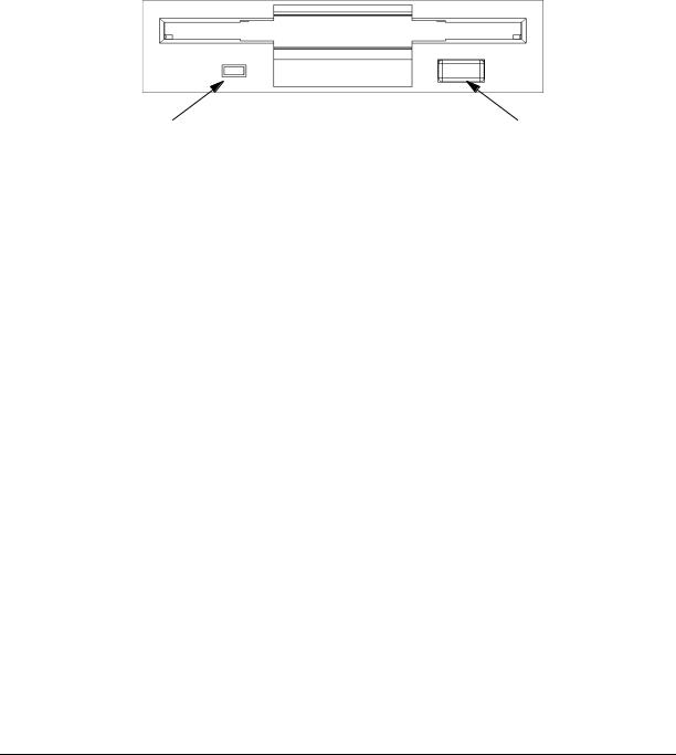
Figure 1-4. shows the operating controls and features of the floppy drive, and Table 1-2. describes those controls and features.
Figure 1-4. Floppy Drive Controls and Features
Busy Indicator |
Eject Button |
Table 1-2. Floppy Drive Controls and Features
Control/Feature |
Purpose |
|
|
Floppy Drive Eject Button |
Push the eject button to remove floppy |
|
diskettes from the drive. |
|
|
Floppy Drive Activity |
The floppy drive LED flashes to |
LED |
indicate the drive is in use. |
|
|
security lock
Access to the mass storage devices is controlled by a security lock on the front panel. Locking the workstation front panel minimizes potential unauthorized user access.
To prevent access to internal components requires the use of the security loop on the rear panel of the workstation. See “unit rear panel controls.”
24 |
Chapter 1 |
 workstation c-class User Manual")
product information
System Unit Rear Panel Connectors
System Unit Rear Panel Connectors
This section describes the following connectors on the system unit’s rear panel:
•Two serial ports (RS-232)
•Two Universal Serial Bus ports (USB)
•LAN connector, 10 BaseT/100 BaseT
•HP parallel IEEE 1284 (printer) connector
•Audio connectors (PCI based, line in, line out, headset, and microphone in)
•Ultra2 Wide LVD (Low Voltage Differential) SCSI
•Ultra Narrow Single-Ended (NSE) SCSI
•TOC (transfer of control) button
•AC power cord connector
•Security loop
NOTE To maintain FCC/EMI compliance, verify that all cables are fully seated and properly fastened.
Figure 1-5. System Unit Rear Panel Connectors
Security Loop
Serial Ports (2)
USB Ports (2)
TOC Button
LAN Port
Parallel Port
Audio Connectors:
Line In
Line Out
Microphone
Headphones
Ultra2 Wide LVD SCSI
AC Power Cord
Connector
Ultra Narrow Single-Ended (NSE) SCSI
Chapter 1 |
25 |
product information
System Unit Rear Panel Connectors
audio connectors
The HP workstation c-class has audio-input and -output capabilities through external input and output connectors on the rear panel and through an internal speaker. The sound is 16-bit, 44 kHz (CD-quality).
The rear panel contains the Audio IN (Stereo line-in) and Microphone (Mic-in), and Audio OUT (Stereo line-out) and Headphones (headphone-out) connectors. This workstation also has a mono internal speaker.
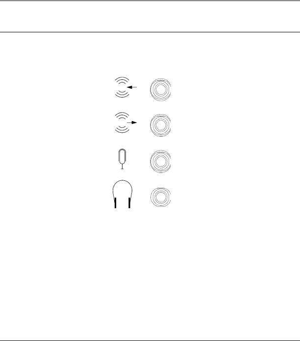
The audio connectors are standard stereo audio mini-jacks (see Figure 1-6).
NOTE Hewlett-Packard recommends using gold-plated plugs available through audio retailers for best quality recording and playback through the external connectors.
Figure 1-6. Audio Connectors
Audio IN
Audio OUT
Microphone IN
Headset
Table 1-3. summarizes the audio electrical specifications for the c-class workstations.
26 |
Chapter 1 |

product information
System Unit Rear Panel Connectors
Table 1-3. Audio Electrical Specifications
Frequency Response |
25 to 20KHz |
|
|
Input Sensitivity/Impedance |
|
|
|
Line in |
2.0V pk/47kohm |
|
|
Microphone in |
22mVpk/1kohm |
|
|
Max Output Level/Impedance |
|
|
|
Line Out |
2.8Vpp/47kohm |
|
|
Headphone |
2.75Vpp/50ohm |
|
|
Speaker (internal) |
5.88Vpp/48ohm |
|
|
Output Impedance |
|
|
|
Line Out |
619ohm |
|
|
Headphone |
118ohm |
|
|
USB connectors
The USB connectors located on the rear panel of the workstation provide an interface for the keyboard and mouse to the system. These USB connectors support only the HP keyboard, scroll mouse and hub. The keyboard and mouse may be plugged into the rear of the workstation or plugged into the USB hub. No other USB configuration is currently supported. Consult the documentation that accompanies each input device for specific information concerning its use.
For more information on the Universal Serial Bus, refer to the following URL:
http://www.usb.org
CAUTION Usage of devices other than USB specification may result in unpredictable functionality and inferior performance of the HP workstation c-class.
NOTE The USB clip on the rear of the chassis provides strain relief for the USB cables.
hp parallel i/o connector
The 25-pin HP Parallel I/O interface uses IEEE 1284 I/O interface protocols to support peripheral devices such as printers and plotters. Consult the documentation that accompanies each peripheral device for specific information concerning its use.
802.3 network connectors
The HP workstation c-class has a built-in Twisted Pair (TP) connector for the 802.3 (ETHERNET) or 10BaseT/100BaseT network. Connections to ThinLAN networks require
Chapter 1 |
27 |

product information
System Unit Rear Panel Connectors
an external transceiver. The workstation automatically selects the correct network setting.
RS-232 serial input/output connectors
There are a variety of peripheral devices that can attach to the RS-232 Serial Input/Output (SIO) ports on this workstation. Refer to the label on the rear of the workstation to locate serial port 1 and serial port 2. Peripheral devices include printers, plotters, modems, and scanners. Consult the documentation that accompanies each peripheral device for specific information concerning its use.
The SIO ports are programmable, allowing functions such as bit rate, character length, parity, and stop bits to be set using the System Administration Manager (SAM) or by selecting a system special device file with the functions already programmed. The SIO Ports are used as interfaces for serial asynchronous devices to the CPU.
Table 1-4. shows the SIO connector pin listings. The serial connectors are 9-pin D-sub connectors. Signal names are those specified in the EIA RS-232 standard.
Table 1-4. Serial I/O Pins
Pin No. |
Signal |
Description |
|
|
|
1 |
DCD |
Data Carrier Detect |
|
|
|
2 |
RXD |
Receive Data |
|
|
|
3 |
TXD |
Transmit Data |
|
|
|
4 |
DTR |
Data Terminal Ready |
|
|
|
5 |
GND |
Ground |
|
|
|
6 |
DSR |
Data Set Ready |
|
|
|
7 |
RTS |
Request To Send |
|
|
|
8 |
CTS |
Clear To Send |
|
|
|
9 |
RI |
Ring Indicator |
|
|
|
SCSI connectors
The c-class workstation has built in SCSI connectors for Ultra2 Wide Low-Voltage Differential (LVD) SCSI and Ultra Narrow Single-Ended (NSE) SCSI. Use the SCSI connectors to connect external SCSI devices such as DDS-format tape drives and CD-ROM drives. Consult the documentation that accompanies each SCSI device for specific information concerning its use. Refer to Appendix B, SCSI Connections, for information about connecting SCSI devices to your workstation.
NOTE There must ALWAYS be a terminator at both ends of a SCSI bus. This means one internal terminator and one external terminator.
28 |
Chapter 1 |

product information
System Unit Rear Panel Connectors
TOC button
The TOC (transfer of control) button interrupts the system and transfers control from the default device to an auxiliary device. A transfer of control saves the state of the processor in Processor Internal Memory (PIM) and begins execution of recovery software at a nonzero location specified by a special location in Page Zero called MEM_TOC. The TOC code is protected by a checksum.
power cord connector
Plug the workstation’s power cord into the power cord connector to provide AC power to the system.
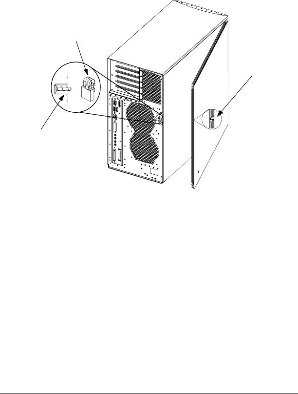
security loop
The security loop provides a means of locking the left side panel with a padlock or other locking device to prevent unauthorized access. To operate the security loop:
1.Inspect left side panel for proper seating in the mainframe chassis.
2.Push in the retractable pin on the spring loaded square fastener.
3.Insert the locking device through the top and bottom holes of the square fastener.
4.Inspect after locking device is in place to assure that the retractable pin is captured in the side panel insert hole.
The internal components of the workstation is now secured. See Figure 1-7. on page 30.
NOTE A locking device is not supplied with the workstation; the customer must supply a lock to use with the security loop.
Chapter 1 |
29 |
product information
System Unit Rear Panel Connectors
Figure 1-7. Security Loop Operation
Security Loop Pin Pushed
In Place By The Padlock
Security Loop Pin
Hole
Security Loop Pin
and Spring
30 |
Chapter 1 |
Loading...