


 Loading...
HP Integrity Superdome 2 Onboard
Administrator User Guide
Abstract
This document contains specific information that is intended for users of this HP product.
HP Part Number: AH337-9001G
Published: November 2013
Edition: 9

© Copyright 2010 – 2013 Hewlett-Packard Development Company, L.P.
Notices
The information contained herein is subject to change without notice. The only warranties for HP products and services are set forth in the express warranty statements accompanying such products and services. Nothing herein should be construed as constituting an additional warranty. HP shall not be liable for technical or editorial errors or omissions contained herein.
Confidential computer software. Valid license from HP required for possession, use or copying. Consistent with FAR 12.211 and 12.212, Commercial Computer Software, Computer Software Documentation, and Technical Data for Commercial Items are licensed to the U.S. Government under vendor's standard commercial license.
Microsoft®, Windows®, and Windows Server® are U.S. registered trademarks of Microsoft Corporation. Java® is a registered trademark of Oracle and/or its affiliates. UNIX® is a registered trademark of the Open Group.
Oracle® is a registered U.S. trademark of Oracle Corporation, Redwood City, California.
Revision History |
|
|
HP Part Number |
Edition |
Publication Date |
AH337-9001A |
First |
August 2010 |
AH337-9001A_ed2 |
Second |
November 2010 |
AH337-9001A_ed3 |
Third |
December 2010 |
AH337-9001B |
Fourth |
April 2011 |
AH337-9001C |
Fifth |
August 2011 |
AH337-9001D |
Sixth |
December 2011 |
AH337-9001E |
Seventh |
December 2012 |
AH337-9001F |
Eighth |
May 2013 |
AH337-9001G |
Ninth |
November 2013 |

Contents |
|
1 Introduction............................................................................................... |
8 |
Overview................................................................................................................................ |
8 |
Access requirements................................................................................................................ |
10 |
Onboard Administrator overview.............................................................................................. |
11 |
Detecting component insertion and removal.......................................................................... |
11 |
Identifying components....................................................................................................... |
11 |
Managing power and cooling............................................................................................. |
12 |
Controlling components...................................................................................................... |
12 |
Managing partitions.......................................................................................................... |
12 |
Interfaces............................................................................................................................... |
12 |
Onboard Administrator user interfaces.................................................................................. |
13 |
Onboard Administrator authentication.................................................................................. |
13 |
Running Onboard Administrator for the first time......................................................................... |
14 |
Logging on to the Onboard Administrator GUI........................................................................... |
15 |
Running the setup wizard......................................................................................................... |
15 |
Using online help................................................................................................................... |
16 |
Changing enclosure and device configurations........................................................................... |
16 |
Recovering the administrator password...................................................................................... |
17 |
2 HP Integrity Superdome 2 Insight Display.................................................... |
18 |
HP Integrity Superdome 2 Insight Display components................................................................. |
18 |
Insight Display overview.......................................................................................................... |
18 |
Running the Insight Display installation...................................................................................... |
19 |
Navigating the Insight Display.................................................................................................. |
23 |
Health Summary screen...................................................................................................... |
24 |
Enclosure Settings screen.................................................................................................... |
25 |
Enclosure Info screen.......................................................................................................... |
26 |
Blade and Port Info screen................................................................................................... |
27 |
Turn Enclosure UID On/Off screen....................................................................................... |
28 |
View User Note screen....................................................................................................... |
29 |
Chat Mode screen............................................................................................................. |
29 |
Insight Display errors............................................................................................................... |
30 |
Power errors...................................................................................................................... |
30 |
Cooling errors................................................................................................................... |
30 |
Location errors................................................................................................................... |
31 |
Configuration errors........................................................................................................... |
31 |
Device failure errors........................................................................................................... |
31 |
3 HP Superdome 2 Door Status Display......................................................... |
32 |
Before running Door Display setup............................................................................................ |
32 |
Setting up the Door Display..................................................................................................... |
32 |
Door Display status menu.................................................................................................... |
36 |
Display Settings menu........................................................................................................ |
38 |
Firmware Update menu....................................................................................................... |
39 |
4 First Time Setup Wizard............................................................................ |
41 |
Before you begin.................................................................................................................... |
41 |
Enclosure Selection screen....................................................................................................... |
41 |
Configuration Management screen........................................................................................... |
42 |
Rack and Enclosure Settings screen........................................................................................... |
43 |
Administrator Account Setup screen.......................................................................................... |
44 |
Local User Accounts screen...................................................................................................... |
45 |
Enclosure Bay IP Addressing screen........................................................................................... |
47 |
Contents 3
Directory Groups screen.......................................................................................................... |
48 |
Directory Settings screen.......................................................................................................... |
49 |
Onboard Administrator Network Settings screen......................................................................... |
50 |
SNMP Settings screen............................................................................................................. |
50 |
Power Management screen...................................................................................................... |
51 |
Finish.................................................................................................................................... |
53 |
5 Navigating Onboard Administrator............................................................ |
55 |
Navigation overview............................................................................................................... |
55 |
Tree view.......................................................................................................................... |
55 |
Graphical view navigation.................................................................................................. |
57 |
6 Complex Overview................................................................................... |
60 |
Complex Overview screen....................................................................................................... |
60 |
Compute Enclosures tab...................................................................................................... |
61 |
Power and Thermal tab....................................................................................................... |
61 |
Complex Information screen..................................................................................................... |
63 |
Status tab......................................................................................................................... |
63 |
Information tab.................................................................................................................. |
65 |
Complex Logs tab.............................................................................................................. |
67 |
Complex CLI Tab............................................................................................................... |
67 |
Complex Information: Firmware Management............................................................................. |
67 |
Complex Firmware Summary screen..................................................................................... |
67 |
Online complex firmware update on Superdome 2................................................................. |
68 |
Introduction.................................................................................................................. |
68 |
Services unavailable...................................................................................................... |
69 |
Management Processor access........................................................................................ |
69 |
IPMI............................................................................................................................ |
70 |
Event logs.................................................................................................................... |
70 |
IPMI Watchdog............................................................................................................. |
70 |
Partition ID................................................................................................................... |
70 |
Console....................................................................................................................... |
71 |
System Firmware Services During Boot, Shutdown, etc........................................................ |
71 |
Affected OS Commands................................................................................................. |
72 |
Network Services to OA................................................................................................. |
72 |
Frequently asked questions:............................................................................................ |
72 |
Known issues:............................................................................................................... |
73 |
hpvminfo command qualifiers fail............................................................................... |
73 |
Newly created HPVM guests cannot be started............................................................. |
73 |
Serviceguard Manager performance degradation and proxy errors................................ |
74 |
cimserver shutdown and startup fail............................................................................ |
74 |
cimauth is unable to add authorizations....................................................................... |
74 |
cprop command qualifiers fail.................................................................................... |
74 |
SMH is unable to query memory or enclosure information.............................................. |
74 |
setboot and related commands are unable to display or modify boot variables................ |
74 |
wbemassist namespace error..................................................................................... |
74 |
par* and vpar* commands fail.................................................................................. |
74 |
Firmware Update screen..................................................................................................... |
74 |
Enclosure DVD Module screen.................................................................................................. |
77 |
7 Configuring HP Integrity Superdome 2 compute enclosures and enclosure |
|
devices...................................................................................................... |
79 |
Viewing the status screens........................................................................................................ |
79 |
Enclosure settings................................................................................................................... |
80 |
Enclosure Settings screen.................................................................................................... |
80 |
Enclosure Information tab............................................................................................... |
82 |
4Contents
AlertMail screen................................................................................................................ |
83 |
Device Power Sequence Device Bays tabs............................................................................. |
85 |
Device Power Sequence Interconnect Bays tab................................................................... |
87 |
Date and Time screen......................................................................................................... |
87 |
Enclosure TCP/IP Settings screen.......................................................................................... |
88 |
Network Access screen....................................................................................................... |
89 |
Trusted Hosts tab........................................................................................................... |
90 |
Anonymous Data tab..................................................................................................... |
91 |
Link Loss Failover screen...................................................................................................... |
91 |
Enclosure Bay IP Addressing screen...................................................................................... |
91 |
SNMP Settings screen........................................................................................................ |
94 |
Configuration Scripts screen................................................................................................ |
96 |
Device Summary screen...................................................................................................... |
97 |
Active to Standby screen..................................................................................................... |
98 |
Onboard Administrator Module................................................................................................ |
98 |
Active Onboard Administrator screen................................................................................... |
98 |
Active Onboard Administrator Status and Information tab................................................... |
99 |
Active Onboard Administrator Virtual Buttons tab............................................................ |
100 |
TCP/IP Settings screen................................................................................................. |
101 |
Certificate Administration screen................................................................................... |
102 |
Certificate Request tab............................................................................................ |
103 |
Active Onboard Administrator Certificate Upload tab.................................................. |
106 |
System log................................................................................................................. |
106 |
Log Options tab..................................................................................................... |
109 |
Standby Onboard Administrator screen.............................................................................. |
109 |
TCP/IP Settings for Standby Onboard Administrator........................................................ |
110 |
Standby Onboard Administrator Virtual Buttons tab......................................................... |
110 |
Standby Certificate Request tab..................................................................................... |
110 |
Standby Onboard Administrator Certificate Upload tab................................................... |
110 |
Device bays......................................................................................................................... |
111 |
Device Bay Overview screen............................................................................................. |
111 |
Device Bay Information - Bay xx screen............................................................................... |
113 |
Device Bay Information tab........................................................................................... |
116 |
Device bay virtual buttons tab....................................................................................... |
118 |
Interconnect bays.................................................................................................................. |
118 |
Interconnect Bay Summary screen...................................................................................... |
118 |
Interconnect Bay Information screen.................................................................................... |
119 |
Interconnect Bay Information tab................................................................................... |
121 |
Interconnect Bay Virtual Buttons tab............................................................................... |
122 |
Port Mapping - Interconnect Bay screen............................................................................... |
122 |
XFM bays............................................................................................................................ |
123 |
XFM Bay Summary screen................................................................................................. |
123 |
XFM Bay Information - Bay screen...................................................................................... |
124 |
XFM Bay Status tab..................................................................................................... |
125 |
XFM Bay Information tab.............................................................................................. |
126 |
XFM Bay Virtual Buttons............................................................................................... |
126 |
GPSM bays......................................................................................................................... |
127 |
GPSM Bay Summary screen.............................................................................................. |
127 |
GPSM Bay Information screen........................................................................................... |
128 |
GPSM Status tab......................................................................................................... |
128 |
GPSM Bay Information tab........................................................................................... |
129 |
GPSM Virtual Buttons................................................................................................... |
129 |
Enclosure power management................................................................................................ |
129 |
Planning power management ........................................................................................... |
129 |
Power and Thermal screen................................................................................................. |
130 |
Contents 5
Power Management screen........................................................................................... |
131 |
Enclosure Power Allocation screen................................................................................. |
132 |
Enclosure Power Meter screen....................................................................................... |
133 |
Power Subsystem screen.................................................................................................... |
133 |
Power Supply Information - Bay screen........................................................................... |
135 |
Fans and cooling management.......................................................................................... |
136 |
Thermal Subsystem screen............................................................................................ |
136 |
Thermal Subsystem Fan Zones tab................................................................................. |
137 |
Superdome 2 Enclosure fan location rules.................................................................. |
139 |
Fan Information - Bay screen......................................................................................... |
139 |
Managing users................................................................................................................... |
140 |
Users/Authentication........................................................................................................ |
140 |
User roles and privilege levels............................................................................................ |
141 |
Role-based user accounts.................................................................................................. |
141 |
Local Users screen............................................................................................................ |
142 |
Add Local User........................................................................................................... |
142 |
Edit Local User............................................................................................................ |
143 |
Edit Local User Certificate Information tab....................................................................... |
145 |
Password Settings screen................................................................................................... |
145 |
Directory Settings screen................................................................................................... |
146 |
Uploading a certificate................................................................................................ |
146 |
Directory Certificate Upload tab.................................................................................... |
147 |
Directory Test Settings tab............................................................................................ |
147 |
Directory Groups............................................................................................................. |
149 |
Add an LDAP Group screen.......................................................................................... |
150 |
Edit an LDAP Group screen........................................................................................... |
151 |
SSH Administration screen................................................................................................ |
152 |
HP SIM Integration screen................................................................................................. |
153 |
Edit Local User Certificate Information tab....................................................................... |
154 |
Two-Factor Authentication screen............................................................................................ |
154 |
Two-Factor Authentication Certificate Information tab............................................................ |
154 |
Two-Factor Authentication Certificate Upload tab................................................................. |
155 |
Signed In users..................................................................................................................... |
155 |
Session Options tab......................................................................................................... |
156 |
Insight Display..................................................................................................................... |
156 |
Management network IP dependencies.................................................................................... |
156 |
8 HP Integrity Superdome 2 IOX Enclosures.................................................. |
157 |
IOX Enclosure Information screen............................................................................................ |
157 |
IOX Power and Thermal screen............................................................................................... |
159 |
IOX Power Subsystem screen.................................................................................................. |
160 |
IOX Power Supply screen.................................................................................................. |
161 |
IOX Thermal Subsystem screen............................................................................................... |
161 |
9 Port mapping......................................................................................... |
163 |
Device bay port mapping for Superdome 2 Compute Enclosures................................................. |
163 |
Device bay port mapping tabular view for Superdome 2 compute enclosures............................... |
163 |
10 Using the CLI....................................................................................... |
164 |
Command line overview........................................................................................................ |
164 |
11 Using the serial connection..................................................................... |
165 |
Setting up Onboard Administrator using the CLI....................................................................... |
165 |
Pinout signals for Onboard Administrator Serial RS232 connector............................................... |
165 |
Using the service port connection........................................................................................... |
166 |
6Contents
12 Using configuration scripts..................................................................... |
167 |
Configuration scripts............................................................................................................. |
167 |
Reset Factory Defaults screen.................................................................................................. |
168 |
13 Troubleshooting.................................................................................... |
169 |
Onboard Administrator error messages................................................................................... |
169 |
Onboard Administrator factory default settings......................................................................... |
178 |
Onboard Administrator SNMP traps....................................................................................... |
179 |
14 Enabling LDAP Directory Services Authentication to Microsoft Active |
|
Directory.................................................................................................. |
181 |
Certificate Services............................................................................................................... |
181 |
Preparing the directory.......................................................................................................... |
181 |
Uploading the DC certificate (optional)................................................................................... |
182 |
Creating directory groups...................................................................................................... |
184 |
Testing the directory login solution.......................................................................................... |
185 |
Troubleshooting LDAP on Onboard Administrator...................................................................... |
185 |
15 Support and other resources................................................................... |
187 |
Before you contact HP........................................................................................................... |
187 |
HP contact information.......................................................................................................... |
187 |
Subscription service.............................................................................................................. |
187 |
Documentation feedback....................................................................................................... |
187 |
Installing HP Insight Remote Support Software.......................................................................... |
187 |
New and changed information in this edition........................................................................... |
188 |
Related information............................................................................................................... |
188 |
Typographic conventions....................................................................................................... |
188 |
A Time zone settings.................................................................................. |
190 |
Africa time zone settings........................................................................................................ |
190 |
Americas time zone settings................................................................................................... |
190 |
Asia time zone settings.......................................................................................................... |
192 |
Universal time zone settings................................................................................................... |
192 |
Oceanic time zone settings.................................................................................................... |
193 |
Europe time zone settings...................................................................................................... |
193 |
Polar time zone settings......................................................................................................... |
194 |
Standard terms, abbreviations, and acronyms............................................... |
195 |
Index....................................................................................................... |
196 |
Contents 7

1 Introduction
Overview
HP Superdome 2 Onboard Administrator is the complex management processor, subsystem, and firmware base used to support HP Integrity Superdome 2 complexes and all the managed devices contained within the complex.
Onboard Administrator provides a single point from which to perform basic management tasks for the following complex devices:
•Compute enclosures
•IOXs
•Server blades
•I/O interconnects
Onboard Administrator performs configuration steps for the complex, enables run-time management and configuration of the complex components, and informs you of problems within the complex through email, SNMP, or the Insight Display.
HP recommends that you read the HP Integrity Superdome 2 User Service Guide for complex specific information before proceeding with the Onboard Administrator setup.
This user guide provides information on the following topics:
•Initial setup and operation of the HP Superdome 2 Onboard Administrator
•Use of the Onboard Administrator GUI
•Use of the compute enclosure Insight Display
•Initial setup and operation of the HP Superdome 2 Door Status Display
The HP Integrity Superdome 2 Onboard Administrator Command Line Interface User Guide covers the use of the CLI.
The HP Superdome 2 Onboard Administrator provides several features designed to simplify management of Superdome 2 enclosures, blades, and interconnects. Compute enclosures within a Superdome 2 complex can be configured with redundant Onboard Administrator modules to provide uninterrupted manageability of the entire complex in the event of a failure of a single Onboard Administrator module.
The following table lists which Onboard Administrator feature is enhanced when an enclosure contains redundant Onboard Administrator modules. For an enclosure with only a single Onboard Administrator module, the table indicates the behavior of the enclosure if the single Onboard Administrator module has failed or is removed.
Table 1 Benefits of using a redundant Onboard Administrator versus a single Onboard Administrator
Onboard Administrator |
Single Onboard |
Single Onboard |
Redundant Onboard |
feature |
Administrator in enclosure |
Administrator failed or |
Administrator in enclosure |
|
|
removed |
|
Power allocation and control Yes. Complete control. of all blades and
interconnects.
Cooling for all blades and Yes. Complete control. interconnects.
No. Power supplies continue |
Yes. Complete control, |
to deliver power to all |
including sustaining a failure |
blades and interconnects. |
of either Onboard |
No power on requests can |
Administrator. |
be made for blades or |
|
interconnects. |
|
No. All enclosure fans will |
Yes. Complete control, |
ramp to an un-managed |
including sustaining a failure |
higher speed to protect |
of either Onboard |
|
Administrator. |
8Introduction

Table 1 Benefits of using a redundant Onboard Administrator versus a single Onboard Administrator
(continued)
Onboard Administrator |
Single Onboard |
Single Onboard |
Redundant Onboard |
feature |
Administrator in enclosure |
Administrator failed or |
Administrator in enclosure |
|
|
removed |
|
|
|
blades and interconnects |
|
|
|
from overheating. |
|
EBIPA. |
Yes. Complete control. |
No. EBIPA IP addresses are |
Yes. Complete control, |
|
|
lost after lease timeout. |
including sustaining a failure |
|
|
|
of either Onboard |
|
|
|
Administrator. |
Ethernet communications to |
Yes. Complete control. |
Onboard Administrator, |
|
server iLO 3, interconnect |
|
management processors |
|
such as Virtual Connect, |
|
which use the Onboard |
|
Administrator/iLO |
|
management port. |
|
Information and health status |
Yes. Complete control. |
reporting for all blades, |
|
interconnects, fans, power |
|
supplies, Onboard |
|
Administrators, and |
|
enclosure through the |
|
Onboard Administrator GUI |
|
or CLI, AlertMail, or SNMP. |
|
Insight Display. |
Yes. Complete control. |
Enclosure DVD. |
Yes. Complete control. |
No. Ethernet management |
Yes. Complete control, |
communications are not |
including sustaining a failure |
available, including internal |
of either Onboard |
management traffic such as |
Administrator. |
Virtual Connect Manager to |
|
other VC modules in the |
|
enclosure. |
|
No. Additionally, no |
Yes. Complete control, |
information is available from |
including sustaining a failure |
the Onboard Administrator, |
of either Onboard |
and no out-of-band |
Administrator. |
information is available from |
|
VCM or iLO 3 on any |
|
server. |
|
No. |
Yes. Complete control, |
|
including sustaining a failure |
|
of either Onboard |
|
Administrator. |
No. |
Yes. Complete control, |
|
including sustaining a failure |
|
of either Onboard |
|
Administrator. |
Onboard Administrator module replacement and stored settings
When replacing an Onboard Administrator or if a failure occurs when using redundant Onboard Administrators:
•Removing an Onboard Administrator module in a Superdome 2 enclosure with a redundant Onboard Administrator module installed results in the other Onboard Administrator module immediately becoming the active Onboard Administrator if it was the standby Onboard Administrator. Only the network settings of the replaced Onboard Administrator network settings are lost.
•If Onboard Administrator complex firmware versions are identical, manually update the replaced Onboard Administrator network settings using the Insight Display. The replaced Onboard Administrator module gets automatically synchronized on all enclosure settings by the active Onboard Administrator.
NOTE: If the enclosure IP mode is enabled, then both Onboard Administrators have the same network settings and no manual update is required.
•If the complex firmware versions are not identical, the Onboard Administrator GUI and Onboard Administrator CLI can be used to synchronize the firmware versions to the most recent version in the modules, followed by synchronization of the active Onboard Administrator configuration settings to the new standby Onboard Administrator module.
Overview 9

IMPORTANT: You cannot update firmware through the HP Superdome 2 Onboard Administrator GUI if you have complex firmware earlier than the Online Firmware Update firmware release.
To update complex firmware if you have complex firmware earlier than the Online Firmware Update firmware release, see the “Update Firmware” section in the HP Integrity Superdome 2 Onboard Administrator Command Line Interface User Guide.
Access requirements
To access the HP Superdome 2 Onboard Administrator web interface, you require the Onboard Administrator IP address and a compatible web browser. You must access the application through HTTPS (HTTP packets exchanged over an SSL-encrypted session).
The Superdome 2 Onboard Administrator web interface requires an XSLT-enabled browser with support for JavaScript 1.3 or the equivalent.
The following browsers are officially supported for use with Onboard Administrator:
•Microsoft Internet Explorer 7.0 or later
•Mozilla Firefox 2 or later
NOTE: Other browsers can be used but are not supported.
Before running the application, you must enable the following browser settings:
•ActiveX (for Microsoft Internet Explorer)
•Cookies
•JavaScript
If you receive a notice that your browser does not have the required functionality, be sure that your browser settings meet the preceding requirements and see “Recovering the administrator password” (page 17).
To access the HP Superdome 2 Onboard Administrator CLI, use the Onboard Administrator IP address and a terminal or terminal application. To access the CLI interface, you must use Telnet or Secure Shell depending on which of these protocols are enabled.
To access the CLI management and notification features, the ports listed on the following table must be open on any router between Onboard Administrator and any computers used to access or monitor Onboard Administrator.
Protocol |
Incoming port |
Outgoing port |
Secure Shell |
22 |
|
Telnet |
23 |
|
SMTP |
|
25 |
Browser access |
80 |
80 |
Browser access encrypted |
443 |
443 |
SNMP get/set |
161 |
|
SNMP traps |
|
162 |
LDAP |
|
636 |
Terminal services pass-through from |
3389 |
|
PC to OA |
|
|
10 Introduction
Protocol |
Incoming port |
Outgoing port |
Virtual media from PC to OA |
17988 |
|
Remote syslog |
|
514 |
LDAP and Remote syslog port number can be changed.
If a protocol is disabled, the corresponding ports are also disabled.
Onboard Administrator overview
NOTE: The Monarch OA is the Active OA in enclosure 1. It provides complex-wide administrative functions, such as partition management, event logs, and error diagnostics. IOX enclosure devices are managed through the Monarch OA.
Many OA settings must be managed on the Monarch OA and are automatically copied to the other OAs in the complex, such as user accounts and settings, power options, and feature enablement. Some settings are managed locally on each OA, such as the IP configuration and OA certificates.
Detecting component insertion and removal
Onboard Administrator provides component control in HP Integrity Superdome 2 Blade Enclosures. Component management begins after the component is detected and identified. The Onboard Administrator detects components in Superdome 2 enclosures through presence signals on each bay. When you insert a component into a bay, or connect an IOX, the Onboard Administrator immediately recognizes and identifies the component. If you remove a component from a bay the Onboard Administrator deletes the information about that component. An IOX will be marked Failed if it is disconnected while the system is active. The Monarch OA must be rebooted to remove an IOX from the complex.
Identifying components
To identify a component, Onboard Administrator reads an FRU EEPROM that contains specific factory information about the component such as product name, part number, and serial number. All FRU EEPROMs in Superdome 2 enclosures are powered on, even if the component is powered off. Therefore, Onboard Administrator can identify the component before granting power. For devices such as fans, power supplies, and Insight Display, Onboard Administrator directly reads the FRU EEPROMs.
•The server blades contain several FRU EEPROMs: one on the server board, which contains server information and embedded NIC information, and one on each installed mezzanine option cards.
•Server blade control options also include extensive blade hardware information including:
◦Blade and partition firmware versions
◦Blade name
◦NIC and option card port IDs
◦Port mapping
•Onboard Administrator provides easy-to-understand port mapping information for each server blade and interconnect module in each enclosure.
The NIC and mezzanine option FRU data informs Onboard Administrator of the type of interconnects each server requires. Before power is provided to a server blade, Onboard Administrator compares this information with the FRU EEPROMs on installed interconnect modules to verify for electronic
Onboard Administrator overview 11

keying errors. For interconnect modules, Onboard Administrator provides virtual power control, dedicated serial consoles, and management Ethernet connections.
While Onboard Administrator is identifying components, the progress appears as steps on the Insight Display. Discovery might take several minutes, and the number of installed mezzanine cards on each server increases the time taken as each card is identified and verified.
Managing power and cooling
The most important Onboard Administrator tasks are power control and thermal management. Onboard Administrator can remotely control the power state of all components in Superdome 2 compute enclosures. For components in device bays on the front of each enclosure, Onboard Administrator communicates with iLO 3 to control blades, and with a microcontroller to control options such as storage blades. A separate microcontroller controls power to the interconnect modules.
After the components are powered on, the Onboard Administrator begins thermal management with Thermal Logic. The Thermal Logic feature in Superdome 2 minimizes power consumption by the enclosure fan subsystem by reading temperature sensors across the entire enclosure. Then, Thermal Logic changes the fan speed in the various zones in the enclosure to minimize power consumption and maximize cooling efficiency.
Controlling components
Onboard Administrator uses embedded management interfaces to provide detailed information and health status of all bays in the enclosure including presence detection signals in each bay, i2c, serial, USB, and Ethernet controllers. Onboard Administrator also offers information on firmware versions for most components in the enclosure and can be used to update those components.
Managing partitions
The Onboard Administrator also enables users to define and manage partitions in a Superdome 2 complex.
An nPartition comprises one or more Superdome 2 Server Blades working as a single system. I/O bays in IOX enclosures are assigned to nPartitions and any I/O component of a server blade, including NICs and mezzanine cards are assigned to the nPartition containing the server blade.
In the complex, each nPartition has its own dedicated portion of the complex hardware which can run a single instance of an operating system. Each nPartition can boot, reboot, and operate independently of any other nPartitions and hardware within the same complex.
An nPartition includes all hardware assigned to the nPartition: all IOX I/O bays, I/O devices, and server blades.
A complex can contain one or more nPartitions, enabling the hardware to function as a single system or as multiple systems.
NOTE: For more information about partition creation and management, see the HP Integrity Superdome 2 Partitioning Administrator Guide.
Interfaces
Each Superdome 2 compute enclosure has several external management interfaces that connect the user to Onboard Administrator. The primary external management interface is the management port for Onboard Administrator, which is an RJ-45 jack providing Ethernet communications not only to Onboard Administrator, but also to every device or interconnect bay with a management processor.
A serial port on the Onboard Administrator module provides full out-of-band CLI access to the Onboard Administrator.
12 Introduction

All Superdome 2 enclosures support two enclosure link connectors that provide private communications among enclosures linked with CAT5 cable. In addition, the enclosure link-up connector provides an enclosure service port that enables you to temporarily connect a personal laptop computer to any linked enclosure Onboard Administrator for local diagnostics and debugging.
NOTE: For complexes that have the HP Superdome 2 Door Status Display, the enclosure service port is routed through the rack-mounted E-Switch.
Each Superdome 2 compute enclosure includes an embedded Insight Display on the front of the enclosure, which provides status and information on all the bays in a Superdome 2 compute enclosure and diagnostic information if the Onboard Administrator detects a problem in the enclosure. The Insight Display configures key settings in the Onboard Administrator, including the IP address of the Onboard Administrator.
Onboard Administrator user interfaces
The following user interfaces to the Onboard Administrator enable control and provide information about the enclosure and installed components:
•Web interface GUI
•Scriptable CLI
•Insight Display
Remote network access to the Onboard Administrator GUI and CLI is available through the management Ethernet port. The serial port of the Onboard Administrator is available for local CLI access. The Superdome 2 compute enclosure link-up port is also available as the service port for temporary local Ethernet access to the Onboard Administrators and devices in linked enclosures using either the GUI or CLI.
NOTE: For complexes that have the HP Superdome 2 Door Status Display, the enclosure service port is routed through the rack-mounted E-Switch.
Access the Insight Display directly through the buttons on the display, or remotely through the Onboard Administrator GUI.
Onboard Administrator authentication
Security is maintained for all Onboard Administrator user interfaces through user authentication. User accounts created in the Onboard Administrator define three user privilege levels and the component bays to which each level is granted access. Onboard Administrator stores the passwords for Local User accounts and can be configured to use LDAP authentication for user group accounts. The Insight Display can be protected by an LCD PIN code or completely disabled.
NOTE: User accounts are managed on the Monarch OA.
Role-based user accounts
Onboard Administrator provides configurable user accounts that can provide complete isolation of multiple administrative roles such as server, LAN, and SAN. User accounts are configured with specific device bay or interconnect bay permissions and one of the three privilege levels:
•Administrator
•Operator
•User
An account with administrator privileges including Onboard Administrator bay permissions can create or edit all user accounts on an enclosure. Operator privileges allow full information access and control of permitted bays. User privileges allow information access, but no control capability.
Interfaces 13
Onboard Administrator requires the user to log in to the web GUI or CLI with an account and password. The account can be a local account where the password is stored on Onboard Administrator, or an LDAP account. The Onboard Administrator contacts the defined LDAP server to verify the user credentials. Two-factor Authentication enables even tighter security for the user management session to Onboard Administrator.
The default Administrator account from the Monarch OA is synchronized to the other OAs in the complex. Use the default credentials from the Monarch OA to access all OAs.
Rather than requiring separate logins to multiple resources (once to each enclosure or once to every server management processor or both), Onboard Administrator enables single-point access. Thus, the administrator can use single sign-on to log in to a single Onboard Administrator and use the web GUI to graphically view and manage the HP Superdome 2 components in the entire complex. For example, an IT administrator can automatically propagate management commands, such as changing the enclosure power mode, throughout the complex.
Running Onboard Administrator for the first time
Setting up a Superdome 2 enclosure using the Onboard Administrator is simplified by using the Insight Display setup process, followed by the use of the Onboard Administrator GUI First Time Setup Wizard or Onboard Administrator CLI to complete the reset of the enclosure settings.
The Onboard Administrator modules and many interconnect modules default to DHCP for the management IP address. If the user has DHCP and connects the Onboard Administrator management port to the DHCP server, then the Onboard Administrator modules and interconnect modules supporting and configured to use the Onboard Administrator internal management network automatically get DHCP addresses from the user DHCP server.
If you do not have a DHCP server for assigning IP addresses to management processors, then you must configure each Onboard Administrator with a static IP address using the Insight Display, then log in to the Onboard Administrator GUI and use the First Time Setup Wizard or log in to the Onboard Administrator CLI and configure and enable EBIPA for device bays and interconnect bays. Enabling EBIPA for a bay enables that server or interconnect module to be replaced and the new module automatically gets the previously configured IP address for that bay. See “Enclosure Bay IP Addressing screen” (page 91) for more information on EBIPA.
The initial credentials to log on to a new Onboard Administrator module are printed on a label on each module. The user is Administrator and the password is unique to each module. This password must be captured by the installer and communicated to the remote Administrator for the first remote logon to the Onboard Administrator GUI or Onboard Administrator CLI.
The enclosure settings can be configured manually or uploaded from a configuration script or file. The web GUI offers a First Time Setup Wizard. The CLI can be accessed from the Onboard Administrator serial port, Ethernet management port, service port, or by using the Enclosure KVM - Onboard Administrator CLI button.
An alternative to manual configuration is to upload a enclosure configuration file to the active Onboard Administrator using either the GUI or CLI with an HTTP, FTP or TFTP network location for the configuration file, or use the GUI, CLI or Insight Display to upload a configuration file from a USB key drive plugged into the active Onboard Administrator USB port.
HP recommends creating an enclosure configuration file to use the GUI, CLI, or Insight Display USB Menu to save the existing configuration to a file. The saved configuration file is a set of CLI text commands for each configuration item. The Onboard Administrator does not save user passwords when it saves a configuration file. The user can edit the configuration file and insert the password commands for each user account—or use the Administrator local account to individually update all user passwords after restoring a previously saved enclosure configuration file.
If the enclosure contains redundant Onboard Administrator modules, the remaining Onboard Administrator updates the new Onboard Administrator with all the settings.
14 Introduction
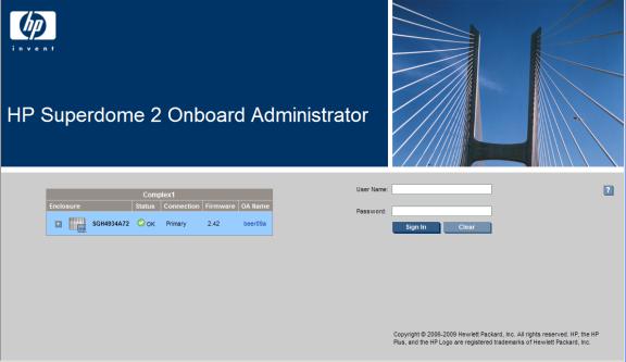
Logging on to the Onboard Administrator GUI
Enter the user name and initial administration password for your HP Superdome 2 Onboard Administrator account found on the tag attached to the Onboard Administrator.
Possible issues that might occur when logging in include:
•Entering the information incorrectly. Passwords are case-sensitive.
•The account information entered not being set up for HP Superdome 2 Onboard Administrator.
•The user name entered has been deleted, disabled, or locked out.
•The password for the account requiring to be changed.
•Attempting to log on from an IP address that is not valid for the specified account.
•The password for the Administrator account being forgotten or lost. To reset the Administrator password, see “Recovering the administrator password” (page 17).
If you continue to have problems signing in, contact your administrator.
Running the setup wizard
To run the setup wizard, log on to Onboard Administrator. The First Time Setup Wizard starts automatically when you log on to Onboard Administrator for the first time. This wizard assists you in setting up the functions of the Onboard Administrator. You can access the setup wizard at any time after initial setup by clicking the Wizards link on the top left of the center screen.
Logging on to the Onboard Administrator GUI 15

For more information, see “First Time Setup Wizard” (page 41).
Using online help
To access online help, click the blue box with the white question mark located at the top right of the screen under the header bar. Online help displays information related to the section of HP Superdome 2 Onboard Administrator that you are navigating.
Changing enclosure and device configurations
After completing the First Time Setup Wizard, return to the Onboard Administrator GUI to make configuration changes at any time. See “Configuring HP Integrity Superdome 2 compute enclosures and enclosure devices” (page 79) for information that helps you make changes to enclosure and device configuration, user setup, and LDAP server settings and LDAP groups.
See “Enclosure power management” (page 129) for information on enclosure power settings.
16 Introduction

Recovering the administrator password
If the administrator password has been lost, you can reset the administrator password to the factory default that shipped on the tag with the Onboard Administrator module. The Onboard Administrator resets a lost password to Lost Password mode. To recover the password and reset the administrator password to the factory default:
IMPORTANT: The password is recovered from the Monarch OA.
1.Connect a computer to the serial port of the active Onboard Administrator using a null-modem cable.
2.With a null-modem cable (9600 N, 8, 1, VT100, locally connect to the Onboard Administrator), open HyperTerminal (in Microsoft Windows) or a suitable terminal window (in Linux).
3.Connect to the active Onboard Administrator.
4.Press the Onboard Administrator reset button for 5 seconds.
5.Press L to boot the system in the Lost Password mode. The password appears as the system reboots.
Recovering the administrator password |
17 |
2 HP Integrity Superdome 2 Insight Display
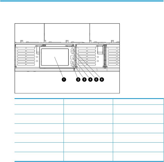
HP Integrity Superdome 2 Insight Display components
Item |
Description |
Function |
1 |
Insight Display screen |
Displays Main Menu error messages |
|
|
and instructions |
2 |
Left arrow button |
Moves the menu or navigation bar |
|
|
selection left one position |
3 |
Right arrow button |
Moves the menu or navigation bar |
|
|
selection right one position |
4 |
OK button |
Accepts the highlighted selection and |
|
|
navigates to the selected menu |
5 |
Down arrow button |
Moves the menu selection down one |
|
|
position |
6 |
Up arrow button |
Moves the menu selection up one |
|
|
position |
Insight Display overview
The Insight Display enables the rack technician to initially configure the enclosure. It also provides information about the health and operation of the enclosure. The color of the Insight Display varies with the condition of the enclosure health:
•Blue— The Insight Display illuminates blue when the enclosure UID is active.
The enclosure UID automatically turns on when the enclosure is powered on for the first time, and can be turned on by selecting Turn Enclosure UID On from the Main Menu or by pressing the enclosure UID button on the management interposer.
18 HP Integrity Superdome 2 Insight Display
When the enclosure UID is on, the Insight Display flashes after two minutes of inactivity. Pressing any button on the Insight Display stops the blinking and reactivates the screen.
•Green— The Insight Display illuminates green when no error or alert conditions exist, and the enclosure is operating normally.
After two minutes of inactivity, the Insight Display light turns off. Pressing any button on the Insight Display reactivates the screen.
•Amber— The Insight Display illuminates amber when the Onboard Administrator detects an issue or alert condition. The screen displays the details of the condition.
After two minutes of inactivity, the Insight Display flashes amber indicating that an error or alert condition exists. If the enclosure UID is on and an error or alert condition exists, the Insight Display illuminates blue as the enclosure UID takes priority over the alert. Pressing any button on the Insight Display reactivates the screen.
•Dark (no power)— The Insight Display has a two-minute inactivity period. If no action is taken and no alert condition exists, the screen light turns off after two minutes. Pressing any button on the Insight Display reactivates the screen.
The Enclosure Health icon is located at the bottom-left corner of every screen, indicating the condition of the enclosure health. Navigate the cursor to the Enclosure Health icon and pressing OK to access the Health Summary screen from any Insight Display screen.
Running the Insight Display installation
When the enclosure is powered on for the first time, the Insight Display launches an installation wizard to guide you through the configuration process. After configuring the enclosure, the Insight Display verifies that no installation or configuration errors are present. If errors are present, the Insight Display guides you through the process of correcting the errors.
To identify the enclosure, the rear enclosure UID light and the background of the Insight Display glow blue when the enclosure is powered on initially.
The Installation Wizard turns on the enclosure UID at the beginning of the installation and turns it off after the installation is complete.
The Enclosure Settings screen is the first screen that appears. The background is blue, because the enclosure UID is active when this screen appears.
1.Review each setting on the Enclosure Settings screen for accuracy.
2.To change any value, navigate the cursor to the menu option to be edited, and then press the OK button.
3.Change the setting to the appropriate value, navigate the cursor to Accept, and then press the OK button to return to the Enclosure Settings menu. Repeat this step until all options on the Enclosure Settings menu are accurate.
Running the Insight Display installation |
19 |
TIP: Select the ? icon to access detailed help information about each setting or topic.
TIP: Within any menu option, navigate the cursor to What is This, and press the OK button to view additional information about each setting, option, or alert.
4.When all settings on the Enclosure Settings menu are accurate, navigate the cursor to Accept All, and then press the OK button to accept the current settings.
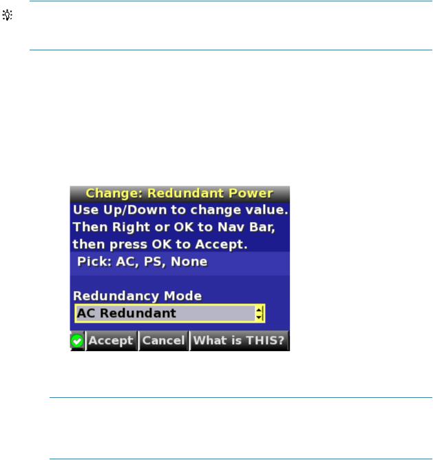
You can change the following options in the Enclosure Settings screen:
•Power Mode—The default setting is AC Redundant. The following selections are valid:
◦AC Redundant
◦Power Supply Redundant
◦None
•Power Limit—The default setting is Not Set. The Power Limit Watts ac setting can be changed in increments of 50 Watts.
NOTE: When calculating the Power Limit Watts ac value, derate the circuit to 80% of the maximum to prevent tripping the circuit breaker (United States only).
NOTE: If your facility cannot support the calculated peak Watts ac, set the Power Watts ac value to match the capability of your facility.
•Dynamic Power —The default setting is Enabled. The following selections are valid:
◦Enabled —Some of the power supplies can be automatically placed on standby to increase overall enclosure power subsystem efficiency.
◦Disabled —All power supplies share the load; the power subsystem efficiency varies based on load.
•OA1 IP Addr— The default setting is DHCP; if no IP address is received, the IP address is 0.0.0.0. The IP address, mask, and gateway are set within this option.
•OA2 IP Addr— If this module is present, the default setting is DHCP; if no IP address is received, the IP address is 0.0.0.0. If only one Onboard Administrator module is installed, the screen displays "Not Present."
20 HP Integrity Superdome 2 Insight Display
•Enclosure Name— The default setting is a unique factory-assigned name. The accepted character values are 0-9, A-Z ,a-z, -, _, and the box character. The box character is used to signal the end of the name.
NOTE: Do not use the box character in the middle of a text box. Entries in text boxes are truncated to the last character before the box character.
TIP: Select Clear from the navigation bar to quickly clear entries in text boxes up to the symbol.
•Rack Name —The default setting is UnnamedRack. The accepted character values are 0-9, A-Z, a-z, -, _, and the box character. The box character is used to signal the end of the name.
•DVD Drive— The DVD connection Settings screen is a table of all the servers with the status of DVD Connection and blade name for that blade.
◦Detach/Attach—Each blade can be individually attached to or detached from the enclosure DVD drive by navigating to that bay and pressing the OK button.
◦Change—Navigates to the Attach:Enclosure DVD menu where you can attach, attach and reboot, or detach all bays from the DVD drive.
◦Navigate to the DVD icon for a blade, and then press the OK button to change the settings for an individual server.
◦Navigate to All Blades, and then press OK to change the settings for all servers in the enclosure.
◦The server name is displayed next to each DVD icon limited to the first ten characters.
5.Navigate to the Accept All button at the bottom of the Enclosure Settings screen, and then press the OK button to accept all the settings and continue.
The installation wizard displays the Check: Installation and Cables screen.
Running the Insight Display installation |
21 |
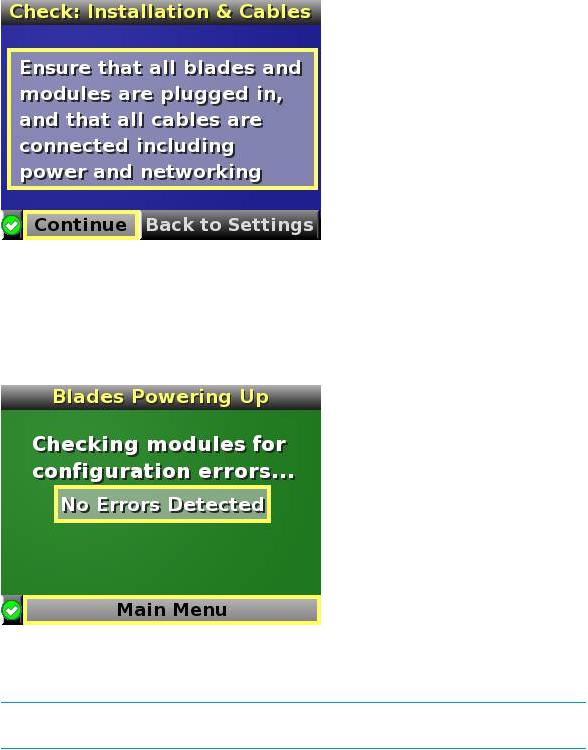
6.Be sure that all components are installed and cabled before continuing. Select Continue, and press the OK button to begin verifying for configuration and installation errors. When Continue is selected, the enclosure UID automatically turns off.
7.If no errors are detected, the rear enclosure UID turns off, and then the Insight Display screen illuminates green. Press the OK button to return to the Main Menu. Enclosure and blade hardware setup and configuration is complete.
If errors are detected, the Insight Display screen glows amber, and the Health Summary screen appears. See “Insight Display errors” (page 30) for more information on troubleshooting configuration and installation errors.
NOTE: Any configuration error prevents the operation of the enclosure and must be corrected immediately.
8.Open a browser and connect to the active Onboard Administrator module using the Onboard Administrator IP address that is configured during the Insight Display Installation Wizard process.
9.Enter the user name and password from the tag supplied with the Onboard Administrator module to access the remote Onboard Administrator web interface and complete the Onboard Administrator First Time Installation Wizard.
22 HP Integrity Superdome 2 Insight Display
10.Navigate to Help, and then press OK to view the Help: DVD Connection screen.
•An exclamation icon indicates no DVD drive and disk is detected or firmware upgrade is needed for this feature.
•A bright green DVD icon indicates the Enclosure DVD media is connected to the blade.
•A gray DVD icon indicates no DVD connection to that blade.
Navigating the Insight Display
Navigate the menus and selections by using the arrow buttons on the Insight Display panel. The first menu that appears is the Main Menu.
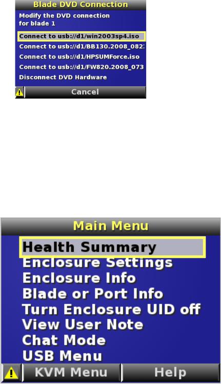
The Main Menu of the Insight Display has the following options:
•Health Summary
•Enclosure Settings
•Enclosure Info
•Blade or Port Info
•Turn Enclosure UID on/off
Navigating the Insight Display |
23 |
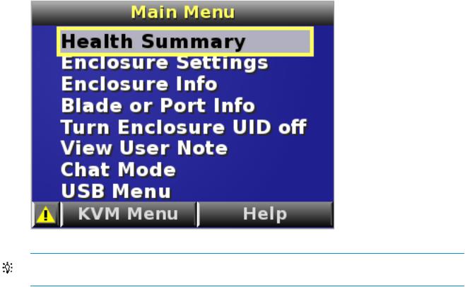
•View User Note
•Chat Mode
If the active Onboard Administrator detects a USB key drive with any *.ROM , *.CFG or *.ISO files, then a USB menu item appears at the bottom of the Main Menu.
If the active Onboard Administrator detects KVM capability, a KVM menu button appears on the navigation bar of the Main Menu. Selecting KVM Menu causes the Insight Display to go blank and starts the VGA connection of Onboard Administrator.
A USB key drive with the appropriate files and KVM capability is present in the Main Menu:
TIP: Within any menu option, navigate the cursor to What is This, and press the OK button to view additional information about each setting, option, or alert.
The navigation bar contains options to:
•Navigate forward and backward through alert screens
•Return to the main menu
•Accept changes to current settings
•Cancel changes to current settings
•Access the Health Summary screen from any screen by selecting the Health Summary icon on the navigation bar
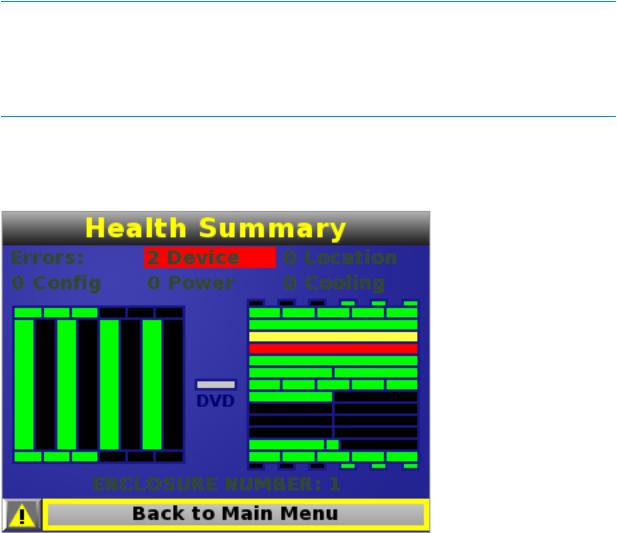
Health Summary screen
The Health Summary screen displays the current status of the enclosure. The Health Summary screen can be accessed by:
•Selecting Health Summary from the Main Menu
•Selecting the Health Summary icon from any Insight Display screen
When an error or alert condition is detected, the Health Summary screen displays the total number of error conditions and the error locations.
24 HP Integrity Superdome 2 Insight Display
Select Next Alert from the navigation bar, and press the OK button to view each individual error condition. The Insight Display displays each error condition in the order of severity. Critical alerts display first (if one exists), followed by caution alerts.
When the enclosure is operating normally, the Health Summary screen displays green. The bright green rectangles are components that are installed and are on. A light green rectangle represents a component that is installed, but powered off with no errors.
When the enclosure is operating normally, the Health Summary screen displays green. The bright green rectangles are components that are installed and on. A dark green rectangle represents a component that is installed, but powered off with no errors. A black rectangle represents an empty bay.
NOTE: A black DVD rectangle indicates no DVD drive is connected to the Onboard Administrator while a dark gray rectangle indicates the DVD drive is present, but that no media is present. A dark green rectangle indicates that media is present, but not actively connected to any server or that all connected servers have issued a disk eject command, so the disk can be removed from the drive. A bright green rectangle indicates that the media is present in the drive and actively connected to at least one server in the enclosure, and the drive tray is locked.
If an error occurs, the Health Summary screen background changes from green to amber and the error is highlighted with yellow rectangles for caution and red rectangles for failures. Overall enclosure health icons at the bottom-left corner of the Insight Display screens indicate the overall enclosure health.
To display the errors, select View Alert and then press the OK button.
To view the details of the error, select Details.
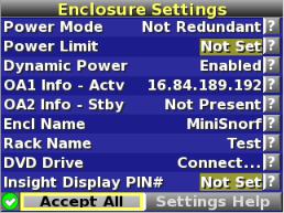
Enclosure Settings screen
The Enclosure Settings screen displays the following setting information about the enclosure:
•Power Mode setting
•Power Limit setting
•Dynamic Power setting
•Active and Standby OA IP addresses
Navigating the Insight Display |
25 |
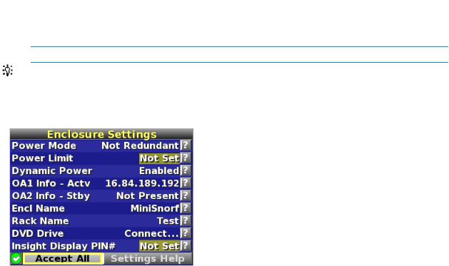
•Enclosure Name
•Rack Name
•DVD Drive
•Insight Display PIN#
NOTE: The DVD Drive setting can attach or detach a CD or DVD loaded in the DVD drive to any or all partitions in the enclosure. This feature can be used to install an operating system or software on the partitions.
TIP: To protect the enclosure settings from changes, set a PIN.
To change the setting or get help for a setting, navigate the cursor to that setting or to ?, and press
OK.
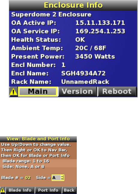
Enclosure Info screen
The Enclosure Info screen displays information about the enclosure, including:
•Active OA IP address
•Active OA Service IP address
•Current health status of the enclosure
•Current enclosure ambient temperature
•Current ac input power to the enclosure
•Enclosure name
•Rack name
26 HP Integrity Superdome 2 Insight Display
Blade and Port Info screen
The Blade and Port Info screen displays information about a specific server blade. On the first screen, select the server blade number, and then press the OK button. Select Blade Info or Port Info, and then press the OK button.
To view information about the server blade, select Blade Info, and then press the OK button.
Navigating the Insight Display |
27 |
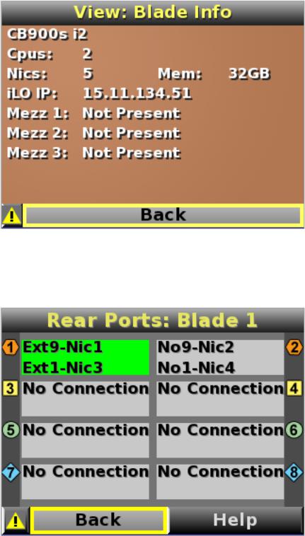
To view the ports used by a specific server blade, select Port Info, and then press the OK button.
The following screen shows a server blade with four embedded NICs. The other interconnect bays are empty. The four embedded NICs are connected to particular port numbers on the interconnect modules.
Turn Enclosure UID On/Off screen
The Main Menu displays Turn Enclosure UID Off when the enclosure UID is active, and displays Turn Enclosure UID on when the enclosure UID is off.
Selecting Turn Enclosure UID On from the main menu turns on the rear enclosure UID LED and changes the color of the Insight Display screen to blue.
28 HP Integrity Superdome 2 Insight Display
Selecting Turn Enclosure UID Off from the main menu turns off the rear enclosure UID LED and changes the color of the Insight Display screen to the current alert condition.
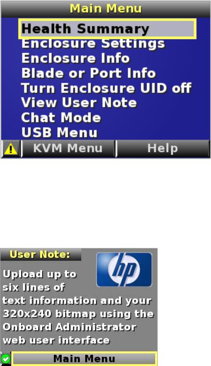
View User Note screen
The View User Note screen displays six lines of text, each containing a maximum of 16 characters. Use this screen to display helpful information such as contact phone numbers. Change this screen using the remote Onboard Administrator user web interface. Both the background bitmap and the text can be changed.
Chat Mode screen
The Chat Mode screen is used by the remote administrator who uses the web interface to send a message to an enclosure Insight Display. The technician uses the Insight Display buttons to select from a set of prepared responses, or dials in a custom response message on the ? line. To send a response back to the Administrator, navigate the cursor to Send, then press the OK button.
The Chat Mode screen has top priority in the Insight Display and remains on the screen until you select Send. The technician can leave this chat screen temporarily and use the other Insight Display screens, then return to the Chat Mode screen from the Main Menu to send a response. After the response, the Chat Mode screen is cleared. Both the A and ? responses appear to the remote Administrator on the LCD Chat web interface.
Navigating the Insight Display |
29 |
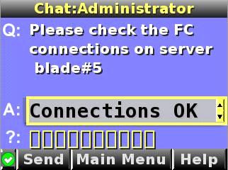
Insight Display errors
The enclosure installation is successful when all errors are corrected. The errors in the following sections are specific to installation and initial configuration of the enclosure.
The following types of errors might occur when installing and configuring the enclosure:
•Power errors
•Cooling errors
•Location errors
•Configuration errors
•Device failure errors
When the enclosure UID LED is off, the Insight Display is illuminated amber when any error condition exists. The navigation bar displays the following selections when an error condition exists:
•Health summary icon— Displays the Health Summary screen
•Fix This— Suggests corrective action to clear the current error
•Next Alert— Displays the next alert, or if none exist, displays the Health Summary screen
•Previous Alert— Displays the previous alert
Power errors
Power errors can occur because of insufficient power to bring up an enclosure. Power errors can occur on server blades, storage blades, or interconnect modules.
To correct a power error:
1.Use the arrow buttons to navigate to Fix This, and then press OK.
2.Review and complete the corrective action suggested by the Insight Display. In most cases, you must either add power supplies to the enclosure or remove the indicated components.
Cooling errors
Cooling errors occur when too few fans are installed in the enclosure or when the existing fans are not installed in an effective configuration. Cooling errors can occur on server blades, storage blades, or interconnect modules.
To correct a cooling error:
30 HP Integrity Superdome 2 Insight Display
Loading...