


 Loading...
Installation and
Reference Guide
HP J3188A
HP 10Base-T Hub-16M

HP 10Base-T Hub-16M (J3188A)
Installation and Reference Guide
© Copyright 1997 Hewlett-Packard Company
All Rights Reserved.
This document contains information which is protected by copyright. Reproduction, adaptation, or translation without prior permission is prohibited, except as allowed under the copyright laws.
Publication Number
J3188-90001
Edition 1
July 1997
Applicable Product
HP 10Base-T Hub-16M (J3188A)
Trademark Credits
MS-DOS® and Microsoft® are U.S. registered trademarks of Microsoft Corporation. Ethernet is a registered trademark of Xerox Corporation. CiscoView is a trademark of Cisco Systems, Inc.
Disclaimer
The information contained in this document is subject to change without notice.
HEWLETT-PACKARD COMPANY MAKES NO WARRANTY OF ANY KIND WITH REGARD TO THIS MATERIAL, INCLUDING, BUT NOT LIMITED TO, THE IMPLIED WARRANTIES OF MERCHANTABILITY AND FITNESS FOR A PARTICULAR PURPOSE. Hewlett-Packard shall not be liable for errors contained herein or for incidental or consequential damages in connection with the furnishing, performance, or use of this material.
Hewlett-Packard assumes no responsibility for the use or reliability of its software on equipment that is not furnished by Hewlett-Packard.
Warranty
See the warranty booklet and the registration form included with the product.
A copy of the specific warranty terms applicable to this product and replacement parts can be obatined from your Cisco Sales and Service Office or authorized dealer.
HP 10Base-T Hub-16M (J3188A)
HP 10Base-T Hub-16M (J3188A)
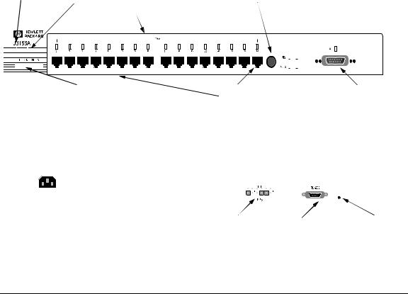
The HP 10Base-T Hub-16M (J3188A) is a multiport repeater with 16 twistedpair ports, and one AUI port. With this hub, you can connect computers, printers, and servers together for file sharing. This hub is compliant with the IEEE 802.3 Type 10Base-T standard and supports both 802.3 and Ethernet networks. The HP Hub-16M follows these two standards by providing these features:
■lighting the hub’s port LED when it detects the connected device is powered on and cable is good.
■retransmitting data that did not successfully arrive at the destination device (collision detection).
■temporarily disabling a port if a device connected to the port persistently causes problems for the network (auto-partioning).
Front of the Hub
|
|
|
MDI/MDI-X |
System |
|
|
switch for |
RPS Status |
Twisted Pair port |
port 16. |
|
|
|
status LEDs |
|
|
|
|
|
|
|
|
|
|
|
|
|
|
|
|
|
|
|
|
|
|
|
|
|
|
|
|
|
|
|
|
|
|
|
|
|
|
|
|
|
|
|
|
|
|
|
|
|
|
|
|
|
|
|
|
|
|
|
|
|
|
|
|
|
|
|
|
|
|
|
|
|
|
|
|
|
|
|
|
|
|
|
|
|
|
|
|
|
|
|
|
|
|
|
|
|
|
|
|
|
|
|
|
|
|
|
|
|
|
|
|
|
|
|
|
|
|
|
|
|
|
|
|
|
|
|
|
|
|
|
|
|
|
|
|
|
|
|
|
|
|
|
|
|
|
|
|
|
|
|
|
|
|
|
|
|
|
|
|
|
|
|
|
|
|
|
|
|
|
|
|
|
|
|
|
|
|
|
|
|
|
|
|
|
|
|
|
|
|
|
|
|
|
|
|
|
|
|
|
|
|
|
|
|
|
|
|
|
|
|
|
|
|
|
|
|
|
|
|
|
|
|
|
|
|
|
|
|
|
|
|
|
|
|
|
|
|
|
|
|
|
|
|
|
|
|
|
|
|
|
|
|
|
|
|
|
|
|
|
|
|
|
|
|
|
|
|
|
|
|
|
|
|
|
|
|
|
|
|
|
|
|
|
|
|
|
|
|
|
|
|
|
|
|
|
|
|
|
|
|
|
|
|
|
|
|
|
|
|
|
|
|
|
|
|
|
|
|
|
|
|
|
|
|
|
|
|
Hub status LEDs (Fault, Security, |
|
|
|
|
|
|
|
|
|
Twisted-pair |
|
|
|
|
|
AUI Connector for |
||||||||||||||||||||||||||||||||||
|
|
Collision, Activity) |
|
|
|
|
|
|
|
|
|
ports |
|
|
|
|
|
External |
|||||||||||||||||||||||||||||||||||
|
|
|
|
|
|
|
|
|
|
|
|
|
|
|
|
|
|
|
|
|
|
|
|
|
|
|
|
|
|
|
|
|
|
|
|
|
|
|
|
|
|
|
|
|
|
|
|
|
|
Transceiver |
|||
Back of the Hub
|
|
|
|
|
|
|
|
|
|
|
|
|
|
|
|
|
|
|
|
|
|
|
|
|
|
|
|
|
|
|
|
|
|
|
|
|
|
|
|
|
|
|
|
|
|
|
|
|
|
|
|
|
|
|
|
|
|
|
|
|
|
|
|
|
|
|
|
RPS connector |
|
|
|
Serial Port |
Password |
||||
|
|
|
|
|
|
|
|
|
|
|
Reset |
|
|
|
|
|
|
|
|
|
|
|
|
Button |
|
iii

HP 10Base-T Hub-16M (J3188A)
Features
Network Connections |
• Sixteen RJ-45 (twisted-pair) ports to connect to end nodes or other devices. |
|
• A Media Dependent Interface (MDI) switch for Port 16 which allows you to connect |
|
either an end node (MDI-X position) or to cascade a hub (MDI position) to the port, |
|
using a “straight-through” twisted-pair cable in both cases. Ports 1 through 15 always |
|
are MDI-X. Port 16 has a factory default of MDI-X, but can be toggled to an MDI state |
|
with the adjacent push-button. |
Easy-to-Use Design
Standards-Based
Compatibility
•An AUI port in the front of the hub for several types of external transceivers, including ThinLAN, twisted-pair, and fiber-optic. The twisted-pair transceiver adds another RJ45 port for a total of 17 twisted-pair ports on the hub. The fiber-optic transceiver allows you to connect your hub to a fiber-optic backbone.
•Hub Status LEDs showing power, activity, collisions, RPS status, fault, security and port status provide quick, easy-to-read hub status information and troubleshooting help.
•Metal brackets (included with the hub) that can be easily attached to the hub for mounting the hub in a standard 19-inch telco rack.
•IEEE 802.3 Type 10Base-T standard compatibility to support both 802.3 and Ethernet networks.
•Advanced embedded SNMP agent code enabling the hub to be managed remotely from a network management station that supports Simple Network Management Protocol (SNMP) over IP (using the configured IP address) or Novell NetWare (IPX). The agent code also provides HP EASE (Embedded Advanced Sampling Environment), which samples network data for enhanced diagnostics from a network management station.
Other Features |
• Extended hub management capabilities, providing a full set of management |
|
commands that can be executed from an ASCII console session. These are described |
|
later in this document in chapter 3, “Managing the Hub.” |
|
• An RS-232 serial port that provides out-of-band management access including: |
|
– An ASCII console to configure, monitor, and troubleshoot the hub. |
|
– Variable baud rates on the hub’s out-of-band management RS-232 port, and |
|
automatic sensing of the selected baud rate when connecting to a terminal device. |
|
– Full V.22bis modem line control for remote out-of-band management access to the |
|
hub. |
|
– Updatable firmware that enables enhancements to be downloaded either from a |
|
computer attached to the out-of-band management port or over the network. |
|
• A Redundant Power Supply (RPS) connector that enables an RPS to be connected to |
|
the hub, providing an alternative redundant power source. |
|
• Advanced integrated design including an Intel i960 RISC processor, 1 megabyte RAM, |
|
and 512 kilobytes of flash EEPROM for configuration and future upgrade capabilities. |
iv

Contents
1 Installing the Hub
Installing and Configuring Your Hub . . . . . . . . . . . . . . . . . . . . . . . . . . . 1-2 1. Verify included parts . . . . . . . . . . . . . . . . . . . . . . . . . . . . . . . . . . . . . . . 1-2 2. Connect the external transceiver . . . . . . . . . . . . . . . . . . . . . . . . . . . . 1-2 3. Verify the hub operates correctly . . . . . . . . . . . . . . . . . . . . . . . . . . . . 1-2 4. Mount the hub . . . . . . . . . . . . . . . . . . . . . . . . . . . . . . . . . . . . . . . . . . . . 1-5 5. Connect the hub to your network . . . . . . . . . . . . . . . . . . . . . . . . . . . 1-7 Connecting Devices to the Hub . . . . . . . . . . . . . . . . . . . . . . . . . . . . . . . . 1-8 Connecting Hubs Together . . . . . . . . . . . . . . . . . . . . . . . . . . . . . . . . . . . 1-8
Interpreting LED Status . . . . . . . . . . . . . . . . . . . . . . . . . . . . . . . . . . . . . . 1-11
Interpreting Hub Status LEDs . . . . . . . . . . . . . . . . . . . . . . . . . . . . . . . . 1-12
Interpreting Port Status LEDs . . . . . . . . . . . . . . . . . . . . . . . . . . . . . . . . 1-13
2 Troubleshooting
Troubleshooting Approaches . . . . . . . . . . . . . . . . . . . . . . . . . . . . . . . . . . . 2-1
Using a Checklist to Diagnose the Hub . . . . . . . . . . . . . . . . . . . . . . . . . |
2-2 |
LED Operation . . . . . . . . . . . . . . . . . . . . . . . . . . . . . . . . . . . . . . . . . . . . . . . . |
2-3 |
Hub Maintenance Tasks . . . . . . . . . . . . . . . . . . . . . . . . . . . . . . . . . . . . . . . |
2-5 |
Testing the Hub Only . . . . . . . . . . . . . . . . . . . . . . . . . . . . . . . . . . . . . . . . |
2-5 |
Clearing a Password for the ASCII Console . . . . . . . . . . . . . . . . . . . . . |
2-5 |
Running Connectivity Tests . . . . . . . . . . . . . . . . . . . . . . . . . . . . . . . . . . . |
2-6 |
Obtaining Firmware Enhancements . . . . . . . . . . . . . . . . . . . . . . . . . . . . |
2-6 |
3 Managing the Hub
Setting up the ASCII Console . . . . . . . . . . . . . . . . . . . . . . . . . . . . . . . . . . 3-1 Starting the Console . . . . . . . . . . . . . . . . . . . . . . . . . . . . . . . . . . . . . . . . . 3-3
Console Command Reference . . . . . . . . . . . . . . . . . . . . . . . . . . . . . . . . . . 3-4
v

A Cables and Connectors
Recommended Cables . . . . . . . . . . . . . . . . . . . . . . . . . . . . . . . . . . . . . . . . |
A-1 |
Twisted-Pair Cable/Connector Pin-Outs . . . . . . . . . . . . . . . . . . . . . . . A-3 Twisted-Pair Cable for Hub-to-Computer Network Connection . . . . A-3
RS-232 Connector and Cable Pin-Outs . . . . . . . . . . . . . . . . . . . . . . . . . A-4 Minimum Cable Pinout for ASCII Console Connection . . . . . . . . . . . A-5 RS-232 Modem Cable . . . . . . . . . . . . . . . . . . . . . . . . . . . . . . . . . . . . . . . A-5 Twisted-Pair Cable Pin Assignments . . . . . . . . . . . . . . . . . . . . . . . . . . A-6
B Specifications
Physical . . . . . . . . . . . . . . . . . . . . . . . . . . . . . . . . . . . . . . . . . . . . . . . . . . . B-1
Electrical . . . . . . . . . . . . . . . . . . . . . . . . . . . . . . . . . . . . . . . . . . . . . . . . . B-1
Environmental . . . . . . . . . . . . . . . . . . . . . . . . . . . . . . . . . . . . . . . . . . . . . B-1
Connectors . . . . . . . . . . . . . . . . . . . . . . . . . . . . . . . . . . . . . . . . . . . . . . . . B-2
Electromagnetic . . . . . . . . . . . . . . . . . . . . . . . . . . . . . . . . . . . . . . . . . . . B-2
CModem Configuration
DNetwork Addressing
Communication Between the Hub and Network Management Station
D-1
IPX Addressing for Novell NetWare . . . . . . . . . . . . . . . . . . . . . . . . . . . D-2 IPX Addressing Notes: . . . . . . . . . . . . . . . . . . . . . . . . . . . . . . . . . . . . . . D-2
IP Addresses for IP and Non-IP Networks . . . . . . . . . . . . . . . . . . . . . D-2 Globally Assigned IP Network Addresses . . . . . . . . . . . . . . . . . . . . . . D-2 Device IP Configuration . . . . . . . . . . . . . . . . . . . . . . . . . . . . . . . . . . . . . D-3
Using BOOTP . . . . . . . . . . . . . . . . . . . . . . . . . . . . . . . . . . . . . . . . . . . . . . . . D-4
The BOOTP Process . . . . . . . . . . . . . . . . . . . . . . . . . . . . . . . . . . . . . . . . D-4
BOOTP Table File Entries . . . . . . . . . . . . . . . . . . . . . . . . . . . . . . . . . . . D-5
E Backup Links
How Backup Links Work . . . . . . . . . . . . . . . . . . . . . . . . . . . . . . . . . . . . . . E-1
Limitations . . . . . . . . . . . . . . . . . . . . . . . . . . . . . . . . . . . . . . . . . . . . . . . . E-2
vi

Additional Notes . . . . . . . . . . . . . . . . . . . . . . . . . . . . . . . . . . . . . . . . . . . |
E-2 |
Examples of Backup Links . . . . . . . . . . . . . . . . . . . . . . . . . . . . . . . . . . . . E-3 How the Backup Function Works . . . . . . . . . . . . . . . . . . . . . . . . . . . . . E-3
Configuring a Backup Link . . . . . . . . . . . . . . . . . . . . . . . . . . . . . . . . . . . . E-5
Configuration/Installation Sequence . . . . . . . . . . . . . . . . . . . . . . . . . . E-5
Identifying the Backup Link . . . . . . . . . . . . . . . . . . . . . . . . . . . . . . . . . . |
E-6 |
Indications of Backup Link Activation . . . . . . . . . . . . . . . . . . . . . . . . . |
E-6 |
Reactivating the Primary Link . . . . . . . . . . . . . . . . . . . . . . . . . . . . . . . . |
E-7 |
F Security Information
Understanding Network Security . . . . . . . . . . . . . . . . . . . . . . . . . . . . . . . F-1
How Intruder Prevention Works . . . . . . . . . . . . . . . . . . . . . . . . . . . . . . . F-2
How Eavesdrop Prevention Works . . . . . . . . . . . . . . . . . . . . . . . . . . . . . F-2
Authorized MAC address . . . . . . . . . . . . . . . . . . . . . . . . . . . . . . . . . . . . . F-2
Setting Inbound Security with Intruder Prevention . . . . . . . . . . . . . F-4 Auto Port Disable . . . . . . . . . . . . . . . . . . . . . . . . . . . . . . . . . . . . . . . . . . . F-5 Send Alarm . . . . . . . . . . . . . . . . . . . . . . . . . . . . . . . . . . . . . . . . . . . . . . . . . F-5
Setting Outbound Security with Eavesdrop Prevention . . . . . . . . . . F-6
G Safety and Regulatory Statements
Mounting Precautions . . . . . . . . . . . . . . . . . . . . . . . . . . . . . . . . . . . . . . . . |
G-1 |
Power Precautions . . . . . . . . . . . . . . . . . . . . . . . . . . . . . . . . . . . . . . . . . . . |
G-2 |
Safety Information . . . . . . . . . . . . . . . . . . . . . . . . . . . . . . . . . . . . . . . . . . . |
G-3 |
Informations concernant la sécurité . . . . . . . . . . . . . . . . . . . . . . . . . . . |
G-4 |
Hinweise zur Sicherheit . . . . . . . . . . . . . . . . . . . . . . . . . . . . . . . . . . . . . . |
G-5 |
Considerazioni sulla sicurezza . . . . . . . . . . . . . . . . . . . . . . . . . . . . . . . . |
G-6 |
Consideraciones sobre seguridad . . . . . . . . . . . . . . . . . . . . . . . . . . . . . |
G-7 |
Safety Information (Japanese) . . . . . . . . . . . . . . . . . . . . . . . . . . . . . . . |
G-8 |
Regulatory Statements . . . . . . . . . . . . . . . . . . . . . . . . . . . . . . . . . . . . . . . |
G-9 |
vii
1
Installing the Hub
This chapter describes how to install the hub. Topics in this chapter include
■installing and configuring the hub
■connecting devices to the hub
■connecting hubs together
■interpreting hub LEDs

Installing the Hub
Installing the Hub
Installing and Configuring Your Hub
Installing and Configuring Your Hub
To install and configure your hub, you must complete five basic tasks. They are:
■locating and verifying the necessary parts
■connecting an external transceiver (if necessary)
■connecting the hub to a power source
■mounting the hub
■connecting the hub to your network
1. Verify included parts
Each Hub-16M has the following components shipped with it:
■HP 10Base-T Hub-16M (J3188A) Installation and Reference Guide— this manual (J3188-90001)
■A U.S./Canada/Mexico (8120-1378) power cord.
■Accessory kit (5064-2053):
•bumper feet (4)
•hub-to-rack screws 10-32 (4)
•bracket-to-hub screws 10-32 (4)
•nylon finishing washer (4)
•bracket-to-hub screws (2)
•AUI retainer assembly
2. Connect the external transceiver
Because of the way the external transceiver protrudes out from hub once it is connected, you may want to install the external transceiver before installing the hub. Inspect your installation site and identify whether enough room will be available for the external transceiver to be connected. Then see your external transceiver guide for installation instructions.
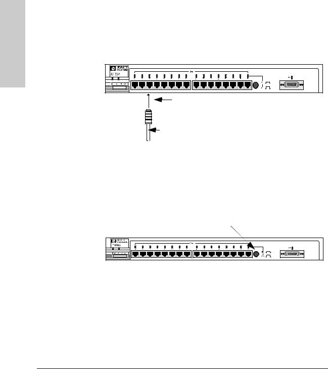
3. Verify the hub operates correctly
Before mounting the hub, connect it to a power source and verify the hub will operate correctly.
1-2
Installing the Hub
Installing and Configuring Your Hub
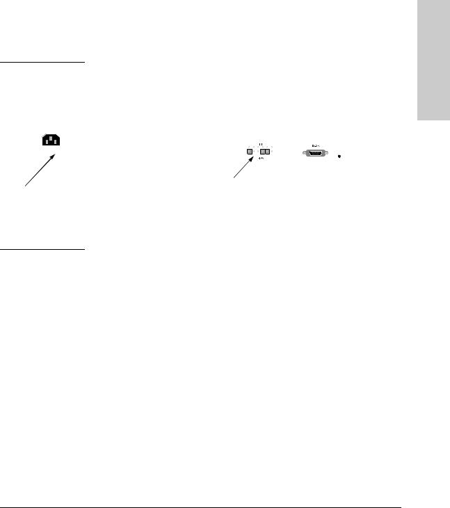
1.Plug the power cord into the hub’s power cord receptacle and into an AC (alternating current) power source. If you are using an RPS as your primary power source, refer to the Cisco RPS User Guide for specific instructions.
N o t e |
If your RPS is the primary power source for the hub, disconnect the AC power |
|||||||||||||
|
|
|
|
|
cord connected directly to the hub for proper operation. |
|||||||||
|
|
|
|
|
|
|
|
|
|
|
|
|
|
|
|
|
|
|
|
|
|
|
|
|
|
|
|
|
|
|
|
|
|
|
|
|
|
|
|
|
|
|
|
|
|
|
|
|
|
|
|
|
|
|
|
|
|
|
|
|
|
|
|
|
|
|
|
|
|
|
|
|
|
|
|
|
|
|
|
|
|
|
|
|
|
|
|
|
|
|
|
|
|
|
|
|
|
|
|
|
|
|
|
|
Hub the Installing
If not connecting a Redundant Power Supply, connect included power cord here and to an alternating current power source.
(Optional) Connect Redundant Power Supply connector cord clip here.
N o t e |
The hub does not have a power switch; it is powered on when the power cord |
|
is plugged in. HP recommends that you only use one power source at a given |
|
time. |
|
|
1-3
Installing the Hub
Installing the Hub
Installing and Configuring Your Hub
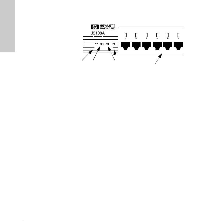
2.Check the LEDs on the hub’s front panel. When the hub is powered on, it performs a power-on self test. See the table below for the LED pattern that occurs during the self test.
|
|
|
|
|
|
|
|
|
|
|
|
|
|
|
|
|
|
|
|
|
|
|
|
|
|
|
|
|
|
|
|
|
|
|
|
|
|
|
|
|
|
|
|
|
|
|
|
|
|
|
|
|
|
|
|
|
|
|
|
|
|
|
|
|
|
|
|
|
|
|
|
|
|
|
|
|
|
|
|
|
|
|
|
|
|
|
|
|
|
|
|
|
|
|
|
|
|
|
|
|
|
|
|
|
|
|
|
|
|
|
|
|
|
|
|
|
|
|
|
|
|
|
|
|
|
|
|
|
|
|
|
|
|
|
|
|
|
|
|
|
|
|
|
|
|
|
|
|
|
|
|
|
|
|
|
|
|
|
|
|
|
|
|
|
|
|
|
|
|
|
|
|
|
|
|
|
|
|
|
|
|
|
|
|
|
|
|
|
|
|
|
|
|
|
|
|
|
|
|
|
|
|
|
|
|
|
|
|
|
|
|
|
|
|
|
|
|
|
|
|
|
|
|
|
|
|
|
|
|
|
|
|
|
|
|
|
|
|
|
|
|
|
|
|
|
|
|
|
|
|
|
|
|
|
|
|
|
|
|
On for 20 seconds, |
On for five |
|
|
|
|
|
|
|
|
|
|
||||||||
then enters |
seconds, then |
|
|
|
On for 20 seconds, |
|
|
||||||||||||
normal operating |
enters normal |
|
|
|
then enters |
|
|
||||||||||||
state. |
operating |
|
|
|
normal operating |
|
|
||||||||||||
|
|
|
|
state. |
|
|
|
state. |
|
|
|||||||||
LED |
Pattern |
|
|
Port LEDs, |
ON for approximately 20 seconds, then enters normal operating |
Fault, Security, |
state. |
AUI |
|
|
|
Activity, |
ON for approximately five seconds, then enters normal operating |
Collision, RPS |
state. |
|
|
System |
Stays ON. |
|
|
Note that once you have connected cables to the hub, a Port LED stays on if link beat has been detected at the port. A Port LED turns off if link beat is not detected. The AUI port stays on if it is enabled.
When the self test completes successfully, the LEDs go into their normal operational states. If a hub hardware fault exists, the hub will not complete self test. This will be indicated by an abnormal LED pattern.
If the self test time elapses and the Fault LED continues to stay on instead of turning off, the hub may have an error condition. If repeating the self test does not correct the problem and the Fault LED still stays continuously on, contact your reseller for replacement information. After the hub has passed its self test, you are ready to mount the hub.
1-4

Installing the Hub
Installing and Configuring Your Hub
4. Mount the hub
|
|
The HP Hub-16M can be mounted in two ways: |
|
|
1. |
in a rack or cabinet |
|
|
2. |
on a table |
|
|
|
The hardware for mounting the hub is included in the accessory kit |
|
|
|
(5064-2053) packed with the hub. Before mounting the hub, unplug it. |
|
|
|
See Appendix G, “Safety and Regulatory Standards,” for general mounting |
|
|
|
precautions. |
|
|
|
Rack or Cabinet Mounting |
|
|
|
|
|
W a r n i n g |
|
The rack or cabinet should be adequately secured to prevent it from |
|
|
|
becoming unstable and/or falling over. Please see Appendix G, “Safety |
|
|
|
and Regulatory Standards,” for precautions and warnings associated with rack |
|
|
|
mounting. |
|
|
1. |
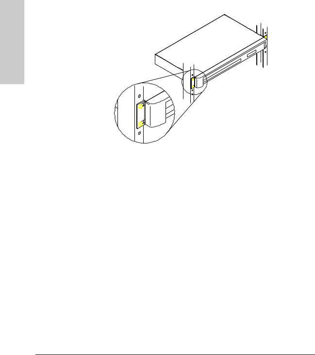
Using a Phillips T-10 screwdriver, attach the mounting brackets to the hub |
|
|
|||
|
|
|
with #10-32 x 7/16" silver screws (included in the accessory kit). |
|
2. |
Position the hub in the rack or cabinet and slide it up or down until the |
|
|
|
|
rack holes line up with the bracket holes. |
|
3. |
Then attach the hub to the rack with the #10-32 x 5/8" black screws and |
|
|
|
|
black nylon washers included in the accessory kit with a Phillips cross- |
|
|
|
head screwdriver. (Some cabinets require number 12-24 screws instead. |
|
|
|
Make sure you have screws that fit your cabinet or rack before mounting |
|
|
|
the hub.) |
Hub the Installing
1-5
Installing the Hub
Installing and Configuring Your Hub
Installing the Hub
Table Mounting
To place the hub on a table or other horizontal surface, no special tools are necessary. Apply the four feet included in the accessory kit onto the bottom of the hub. Be certain to pick a sturdy table in an uncluttered area. You may want to secure the hub’s cables to the leg of the table to prevent people from tripping over them.
1-6

Installing the Hub
Installing and Configuring Your Hub
5. Connect the hub to your network
Reconnect the hub to either an AC power source or the RPS, depending on which source you are using. With the hub mounted, you are now ready to connect the hub to your network. Typical hub connections are:
■hub-to-device connections. Connecting to network devices such as computers, and printers.
■hub-to-hub connections. Connecting to another HP 10Base-T hub, or other Ethernet hub.
■hub-to-network backbones. Connecting to a network backbone.
This section describes the different ways you can connect your hub to your network.
Hub the Installing
1-7
Installing the Hub
Installing the Hub
Installing and Configuring Your Hub
Connecting Devices to the Hub
To connect a device to the hub, push the RJ-45 plug into the RJ-45 jack until the tab on the plug clicks into place.
RJ-45 Connector
unshielded twisted-pair cable Category 3, 4, or 5
Cat 3, 4 maximum distance: 100 meters
Connecting Hubs Together
Twisted-Pair Cascade Connections
To expand your network, the hub can be connected to other hubs with straight-through cable by using the Media Dependent Interface (MDI) switch.
MDI/MDI-X switch
The MDI/MDI-X switch controls how the signals are sent through the twistedpair cable connected to Port 16. The hub is shipped with the switch in the MDI- X position. The switch has two positions:
■In the MDI position, use Port 16 to connect your hub to another hub. In this position, the hub reverses the Tx and Rx port pairs for you. This allows you to use “straight-through” cable rather than “cross-over” cable to connect two hubs together. The cable can be up to 100 meters in length.
■In the MDI-X position, use Port 16 to connect your hub to a PC or similar device using “straight-through” cable.
1-8
Installing the Hub
Installing and Configuring Your Hub
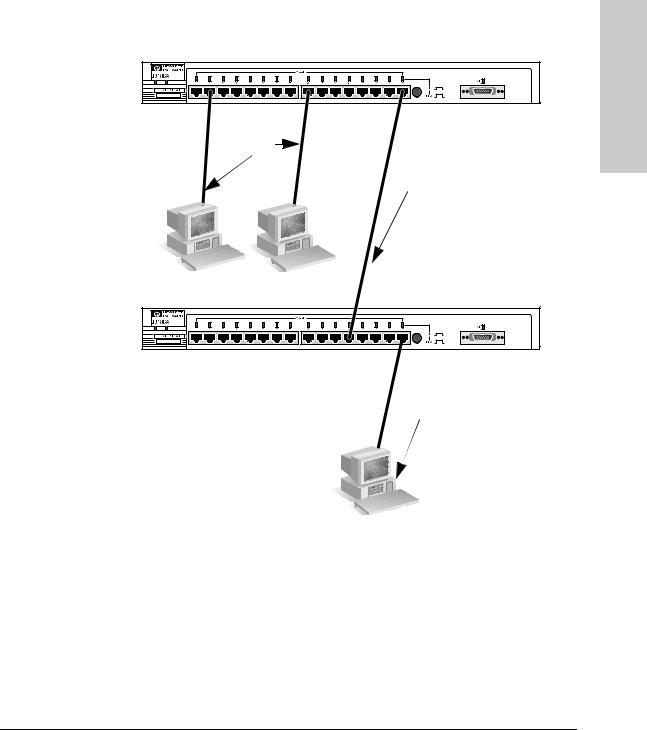
In the following illustration, the first hub is connected to two end nodes and to a second hub. Note the second hub shows Port 16 connecting to a PC, using a straight through cable with the port in the MDI-X position.
Straight-
Through
Cable from
Hub to PCs Hub attached to Port 16: switch in MDI position and straight-through cable is used.
Up to 100 meters
PC attached to Port 16: switch in MDI-X position and straightthrough cable is used.
Hub the Installing
ThinLAN Connections
With an HP ThinLAN External Transceiver for 10Base2 networks, you can connect your hub or a stack of hubs to a thin LAN network. The following illustration shows a hub with an HP ThinLAN External Transceiver.
1-9

Installing the Hub
Installing and Configuring Your Hub
Installing the Hub
You can connect up to 30 hubs together on a common ThinLAN segment. The ThinLAN segment can include a computer attached to a hub at one end of the segment that can communicate with a computer attached to another hub at the other end of the segment. By using the BNC port on the module, the maximum repeater hop-count increment through the entire segment is only two. The following illustration shows you how to connect three hubs together from one ThinLAN port to another.
50-ohm |
Hub-16M |
terminator |
|
ThinLAN coax |
|
connecting the |
|
hubs together |
Hub-16U |
HP AdvanceStack 10Base-T Hub-24
50-ohm terminator
N o t e |
Each ThinLAN cable segment must be terminated using a 50-ohm terminator |
|
at each end. In the illustration above, a 50-ohm terminator is placed at each |
|
end of the cable segment. |
|
|
1-10
Installing the Hub
Interpreting LED Status
Connecting the Hub-16M to a Fiber-Optic Backbone
With an HP Fiber-Optic external transceiver for 10Base-FL networks, you can connect your hub to a fiber-optic backbone. The following illustration shows a hub with an HP Fiber-Optic external transceiver connected to a fiber-optic backbone:
Fiber-optic cable to a fiber-optic  backbone
HP J2606A Fiber-Optic
For more information about cabling configuration, see the documentation accompanying the optional transceiver modules.
Interpreting LED Status
Two types of LEDs exist on the hub. They are:
■Hub Status LEDs. These LEDs reflect certain conditions that exist on the hub at large and are not explicitly referring to a given port.
■Port Status LEDs. These LEDs reflect basic conditions (for example, Link Beat being enabled) that exist on a specific port.
Status information for both are described in the following tables.
Hub the Installing
1-11

Installing the Hub
Installing the Hub
Interpreting LED Status
Interpreting Hub Status LEDs
The hub status LEDs indicate whether the hub is functioning properly. For further details on error conditions indicated by the Status LEDs, see chapter
2, “Troubleshooting”.
LED |
State |
Meaning of LED |
|
|
|
|
|
SYSTEM |
On |
The hub is receiving power. |
|
(Power) |
Off |
The hub is not receiving power. |
|
(green) |
|||
|
|
||
|
|
|
|
ACT |
Flickering |
ON while a packet is being transmitted. Normally, the LED appears |
|
(Activity) |
|
to flicker. In heavy traffic, it may appear on all the time. |
|
(green) |
|
|
|
|
|
|
|
FLT |
On |
An error has been detected on the hub. |
|
(Fault) |
Off |
No error has been detected on the hub. |
|
(Orange) |
Flash |
Flashes simultaneously with port LEDs, indicating the port is |
|
|
|
partitioned. |
|
|
|
|
|
SEC |
On |
A security violation has occurred. |
|
(Security) |
Off |
Hub security has not been violated. |
|
(Orange) |
Flash |
Flashes simultaneously with port LEDs, indicating the port had a |
|
|
|
security violation. |
|
|
|
|
|
RPS |
On |
The RPS is providing power. |
|
(RPS) |
Off |
The RPS is not providing power. |
|
(green) |
|
|
|
|
|
|
|
COL |
Flickering |
This LED is on while a collision is detected. If it appears on |
|
(Collision) |
|
continuously (with no flicker), it is a possible indicator of a network |
|
(orange) |
|
fault or an improperly terminated cable. |
|
|
|
|
1-12

Installing the Hub
Interpreting LED Status
Interpreting Port Status LEDs
The following table provides LED port information.
LED |
State |
Meaning of LED |
|
|
|
|
|
Twisted-pair |
On |
Link beat is detected from the attached node. |
|
Port (green) |
|
|
|
Off |
The port is not receiving the link beat signal from the attached |
||
|
|||
|
|
node. |
|
|
|
|
|
|
Slow |
The port has been auto-partitioned. This port has been auto- |
|
|
Flash* |
partitioned (disabled) due to excessive collisions. This port will |
|
|
|
reenable when the connected device no longer causes |
|
|
|
collisions. |
|
|
|
|
|
AUI |
On |
The AUI port is enabled. |
|
Port (green) |
|
|
|
Off |
The AUI port is disabled. |
||
|
|||
|
|
|
|
|
Slow |
The port has been auto-partitioned. |
|
|
Flash |
|
|
|
|
|
* The slow flash is approximately once every 1.5 seconds.
Hub the Installing
1-13

2
Troubleshooting
This chapter describes ways to troubleshoot the hub. Topics covered are:
■troubleshooting approaches
■using a checklist to diagnose the hub
■interpreting the LED pattern during self test
■hub maintenance tasks
Troubleshooting Approaches
There are three primary ways to diagnose hub problems:
■By checking the LEDs on the front of the hub as described in the section,
“Using a Checklist to Diagnose the Hub” later in this chapter.
■By using the ASCII console’s diagnostic functions as described in chapter 3, “Managing the Hub.”
■By using the CiscoView network management application as described in the CiscoView online help.

Troubleshooting
Using a Checklist to Diagnose the Hub
Using a Checklist to Diagnose the Hub
Use the following table to diagnose the problem with your HP Hub-16M.
|
|
Problem |
Solution |
|
|
|
|
|
|
How do I reset the hub? |
Remove the plug on the power cord from the |
|
|
|
power source and reconnect it. |
|
|
|
|
|
|
None of the LEDs are on. |
Verify that the power cord is plugged into an |
|
|
|
active power source and to the hub. Make sure |
|
|
|
these connections are snug. Try power cycling |
|
|
|
|
|
|
|
the hub by unplugging and plugging the hub |
Troubleshooting |
|
|
back in. |
|
|
If the Power LED is still not on, verify the AC |
|
|
|
|
source works by plugging another device into |
|
|
|
the outlet. Or try plugging the hub into a different |
|
|
|
outlet or try a different power cord. |
|
|
|
If this condition persists, call your |
|
|
|
HP-authorized LAN dealer or HP representative |
|
|
|
for assistance. |
|
|
|
|
|
|
I lost the password. |
Press the password reset button for 10 seconds. |
|
|||
|
|
|
See page 2-4 for more details. |
|
|
|
|
|
|
IP configuration errors have been |
Use the ASCII console’s IP Configuration |
|
|
reported. |
function as described in the chapter 3, |
|
|
|
“Managing the Hub.” |
|
|
|
|
|
|
I want to see if each cable is connected |
Run TEstlink. See the command description in |
|
|
correctly. |
chapter 3, “Managing the Hub.” |
|
|
|
|
|
|
A user can’t send data to another user. |
Use the Connectivity tests in the ASCII console |
|
|
|
or in CiscoView to test the cabling. The tests are |
|
|
|
described in this chapter. |
|
|
|
|
|
|
The Fault LED is on. |
Remove the plug on the power cord from the |
|
|
|
power source and reconnect it. If problem |
|
|
|
persists, the device has an internal failure. |
|
|
|
Contact your HP authorized dealer or reseller. |
|
|
|
|
|
|
The Security LED is flashing. How do I |
Use the ASCII console or CiscoView to view the |
|
|
get it to stop? |
intruder log and clear the security violations. |
|
|
|
|
Most problems with the hub can be diagnosed using the LEDs on its front panel. The following section describes the normal LED pattern during selftest, and LED patterns that indicate error conditions on the hub.
2-2

Troubleshooting
LED Operation
LED Operation
The tables on the following pages list the hub’s LEDs, their possible states, and diagnostic tips to resolve any error conditions.
LED patterns indicating problems |
|
|
Diagnostic Tips |
|
|
||||
|
|
|
|
|
|
|
|
|
|
Power |
Coll |
Port LED |
Sec |
|
Fault |
RPS |
|
|
|
|
|
|
|
|
|
|
|
|
|
OFF |
* |
* |
* |
|
* |
* |
Verify that the power cord is plugged |
|
|
|
|
|
|
|
|
|
into an active power source and to the |
|
|
|
|
|
|
|
|
|
hub. Make sure these connections are |
|
|
|
|
|
|
|
|
|
snug. Try power cycling the hub by |
|
|
|
|
|
|
|
|
|
|
||
|
|
|
|
|
|
|
unplugging and plugging the hub back |
|
|
|
|
|
|
|
|
|
in. |
|
Troubleshooting |
|
|
|
|
|
|
|
If the Power LED is still not on, verify the |
|
|
|
|
|
|
|
|
|
AC source works by plugging another |
|
|
|
|
|
|
|
|
|
device into the outlet. Or try plugging |
|
|
|
|
|
|
|
|
|
the hub into a different outlet or try a |
|
|
|
|
|
|
|
|
|
different power cord. |
|
|
|
|
|
|
|
|
|
If this condition persists, call your |
|
|
|
|
|
|
|
|
|
HP-authorized LAN dealer or HP |
|
|
|
|
|
|
|
|
|
representative for assistance. |
|
|
|
|
|
|
|
|
|
|
|
|
ON |
* |
OFF |
* |
|
* |
* |
Check cabling on the indicated port all |
|
|
|
|
|
|
|
|
|
the way out to the device attached to |
|
|
|
|
|
|
|
|
|
that port. Faulty wiring or a bad |
|
|
|
|
|
|
|
|
|
connection could exist somewhere in |
|
|
|
|
|
|
|
|
|
that connection. |
|
|
|
|
|
|
|
|
|
The end node or hub attached to the |
|
|
|
|
|
|
|
|
|
port is off. |
|
|
|
|
|
|
|
|
|
The port may be disabled. Use the |
|
|
|
|
|
|
|
|
|
ASCII console or management |
|
|
|
|
|
|
|
|
|
application to enable the port. |
|
|
|
|
|
|
|
|
|
If Port 16, check the position of the |
|
|
|
|
|
|
|
|
|
MDI/MDI-X switch. See the figure in |
|
|
|
|
|
|
|
|
|
chapter 1 that details the MDI/MDI-X |
|
|
|
|
|
|
|
|
|
switch. |
|
|
|
|
|
|
|
|
|
|
|
|
ON |
ON |
* |
* |
|
* |
* |
Very frequent collisions are occurring, |
|
|
|
|
|
|
|
|
|
which could indicate a network fault or |
|
|
|
|
|
|
|
|
|
improperly terminated cable. |
|
|
|
|
|
|
|
|
|
|
|
|
*This LED is not important for the diagnosis. |
|
|
|
||||||
|
|
|
|
|
|
|
|
|
|
2-3

Troubleshooting
LED Operation
Troubleshooting
LED patterns indicating problems |
|
|
Diagnostic Tips |
||||
|
|
|
|
|
|
|
|
Power |
Coll |
Port LED |
Sec |
|
Fault |
RPS |
|
|
|
|
|
|
|
|
|
ON |
* |
Fast |
Fast |
|
* |
* |
A security violation has occurred on |
|
|
Flash |
Flash |
|
|
|
the port that is flashing. See SEcure |
|
|
|
|
|
|
|
command for definition and details in |
|
|
|
|
|
|
|
Chapter 3. |
|
|
|
|
|
|
|
|
ON |
* |
Slow |
* |
|
Slow |
* |
The port has been auto-partitioned |
|
|
Flash |
|
|
Flash |
|
because of an excessive collision |
|
|
|
|
|
|
|
condition. Check cable connections |
|
|
|
|
|
|
|
and status of attached network devices |
|
|
|
|
|
|
|
for causes of the excess collisions. The |
|
|
|
|
|
|
|
hub will automatically recover after |
|
|
|
|
|
|
|
certain IEEE 802.3 criteria are |
|
|
|
|
|
|
|
successfully met. |
|
|
|
|
|
|
|
|
ON |
* |
* |
Fast |
|
* |
* |
Network management security |
|
|
|
Flash |
|
|
|
violation occurred. See SEcure |
|
|
|
|
|
|
|
command for details. |
|
|
|
|
|
|
|
|
ON |
* |
* |
* |
|
ON |
* |
The hub has failed its self-test. Power- |
|
|
|
|
|
|
|
cycle the hub. If this condition persists, |
|
|
|
|
|
|
|
call your HP-authorized LAN dealer or |
|
|
|
|
|
|
|
HP representative for assistance. |
|
|
|
|
|
|
|
|
ON |
* |
* |
* |
|
* |
OFF |
The internal power supply is operating |
|
|
|
|
|
|
|
properly and the RPS is not being used. |
|
|
|
|
|
|
|
|
ON |
* |
* |
* |
|
* |
ON |
The internal power supply has failed or |
|
|
|
|
|
|
|
has been unplugged and the RPS has |
|
|
|
|
|
|
|
been activated as the current |
|
|
|
|
|
|
|
operating power supply. |
|
|
|
|
|
|
|
|
*This LED is not important for the diagnosis. |
|
||||||
|
|
|
|
|
|
|
|
2-4
Troubleshooting
Hub Maintenance Tasks
Hub Maintenance Tasks
There are several hub maintenance tasks you can perform. They include:
■testing the hub only
■clearing a password from the ASCII console
■running connectivity tests
Each of these tasks is described in the following sections.
Testing the Hub Only
If you believe that the hub is not operating correctly, remove and reinsert the power cord for that hub. This procedure will cause the hub to complete its power-on self-test. If any error conditions exist in the hub, the LEDs should display the condition.
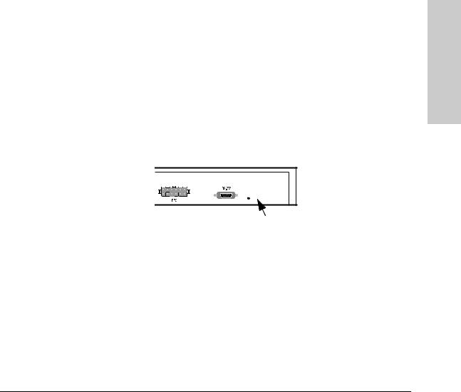
Clearing a Password for the ASCII Console
You can use the Password Reset button to clear a forgotten console password that was previously configured on the hub. The password is configured from the ASCII console.
Troubleshooting
Password
Reset
To clear the password, follow these steps:
1.Verify the hub has powered-up, passed power-on test, and that the System LED is lit.
2.Press the Password Reset button on the back of the hub for 10 seconds.
2-5
Troubleshooting
Troubleshooting
Hub Maintenance Tasks
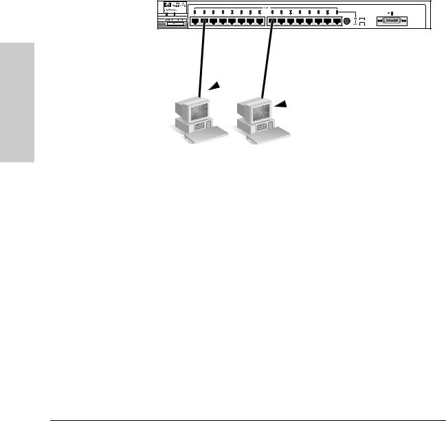
Running Connectivity Tests
Both the hub and cabling can be tested by running an end-to-end communications test -- a test that sends known data from one network device to another through the hub -- such that you can verify that the data was correctly transmitted between the devices.
PC sending test packets.
PC responding to the test packets.
See your LAN adapter’s manual for information on running an end-to-end communication test.
Obtaining Firmware Enhancements
In the future, Hewlett-Packard may provide improvements to this product through firmware upgrades. The upgrade code can be downloaded from a PC attached to the hub’s RS-232 port or over the network. The update procedures are described in documents that come with the firmware enhancements.
You can determine the current firmware version on the hub from the ASCII console. Look for the SNMP Agent EEPROM version number to determine the revision. When you access the console, the version number appears.
2-6
Loading...