


 Loading...
 Integrity Superdome Server User Manual")
QuickSpecs
HP Integrity Superdome Servers: 16-way, 32-way,
and 64-way
Overview
DA - 11717 Worldwide — Version 1 — June 30, 2003 |
Page 1 |

QuickSpecs
HP Integrity Superdome Servers: 16-way, 32-way,
and 64-way
Overview
At A Glance
The latest release of Superdome, HP Integrity Superdome supports the new and improved sx1000 chip set. HP Integrity Superdome supports Itanium 2 1.5- GHz processors in mid 2003, and the next generation PA RISC processor, PA 8800 and the mx2 processor module based on two Itanium 2 processors in early 2004.
Throughout the rest of this document, the term HP Integrity Superdome with Itanium 2 1.5-GHz processors will be referred to as simply "Superdome".
Superdome with Itanium 2 1.5-GHz processors showcases HP's commitment to delivering a 64-way Itanium server and superior investment protection. It is the dawn of a new era in high end computing with the emergence of commodity based hardware.
Superdome supports a multi OS environment. The multi OS environment offered by Superdome is listed below.
NOTE: Superdome supports both Red Hat Enterprise Linux AS 3 and Debian Linux. Throughout the rest of this document, the two flavors will be collectively referred to as Linux.
NOTE: For information on upgrades from existing Superdome systems to HP Integrity Superdome systems, please refer to the "Upgrade" section.
NOTE: This information can also be found in ESP at:
http://esp.mayfield.hp.com:2000/nav24/ppos/servers/gen/PriceAvailConfig/59815790/cgch2/cgch2sub8
HP-UX 11i version 2 |
Improved performance over PA 8700 |
|
Investment protection through upgrades from existing Superdomes to next generation Itanium 2 processors |
|
|
Windows Server 2003 |
Extension of industry standard computing with Windows further into the enterprise data center |
Datacenter Edition for |
Increased performance and scalability over 32-bit implementations |
Itanium 2 |
Lower cost of ownership versus proprietary solutions |
|
Ideal for scale up database opportunities such as SQL Server 2000 (64-bit) |
|
Ideal for database consolidation opportunities such as consolidation of legacy 32-bit versions of SQL Server 2000 |
|
to SQL Server 2000 (64-bit) |
|
|
Linux |
Extension of industry standard computing with Linux further into the enterprise data center |
|
Lower cost of ownership versus proprietary solutions |
|
|
DA - 11717 Worldwide — Version 1 — June 30, 2003 |
Page 2 |

QuickSpecs
HP Integrity Superdome Servers: 16-way, 32-way,
and 64-way
Overview
Superdome Service |
Superdome continues to provide the same positive Total Customer Experience via industry-leading HP Services, as with |
Solutions |
existing Superdome servers. The HP Services component of Superdome is as follows: |
|
HP customers have consistently achieved higher levels of satisfaction when key components of their IT infrastructures |
|
are implemented using the Solution Life Cycle. The Solution Life Cycle focuses on rapid productivity and |
|
maximum availability by examining customers' specific needs at each of five distinct phases (plan, design, |
|
integrate, install, and manage) and then designing their Superdome solution around those needs. HP offers three |
|
pre configured service solutions for Superdome that provides customers with a choice of lifecycle services to address |
|
their own individual business requirements. |
|
Foundation Service Solution: This solution reduces design problems, speeds time to production, and |
|
lays the groundwork for long term system reliability by combining pre installation preparation and |
|
integration services, hands on training and reactive support. This solution includes HP Support Plus 24 to |
|
provide an integrated set of 24x7 hardware and software services as well as software updates for selected HP |
|
and third party products. |
|
Proactive Service Solution: This solution builds on the Foundation Service Solution by enhancing the |
|
management phase of the Solution Life Cycle with HP Proactive 24 to complement your internal IT |
|
resources with proactive assistance and reactive support. Proactive Service Solution helps reduce design |
|
problems, speed time to production, and lay the groundwork for long term system reliability by combining |
|
pre installation preparation and integration services with hands on staff training and transition assistance. |
|
With HP Proactive 24 included in your solution, you optimize the effectiveness of your IT environment with |
|
access to an HP certified team of experts that can help you identify potential areas of improvement in key IT |
|
processes and implement necessary changes to increase availability. |
|
Critical Service Solution: Mission Critical environments are maintained by combining proactive and |
|
reactive support services to ensure maximum IT availability and performance for companies that can't |
|
tolerate downtime without serious business impact. Critical Service Solution encompasses the full spectrum |
|
of deliverables across the Solution Lifecycle and is enhanced by HP Critical Service as the core of the |
|
management phase. This total solution provides maximum system availability and reduces design |
|
problems, speeds time to production, and lays the groundwork for long term system reliability by combining |
|
pre installation preparation and integration services, hands on training, transition assistance, remote |
|
monitoring, and mission critical support. As part of HP Critical Service, you get the services of a team of HP |
|
certified experts that will assist with the transition process, teach your staff how to optimize system |
|
performance, and monitor your system closely so potential problems are identified before they can affect |
|
availability. |
|
HP's Mission Critical Partnership: This service offering provides customers the opportunity to create a custom |
|
agreement with Hewlett Packard to achieve the level of service that you need to meet your business requirements. |
|
This level of service can help you reduce the business risk of a complex IT infrastructure, by helping you align IT |
|
service delivery to your business objectives, enable a high rate of business change, and continuously improve service |
|
levels. HP will work with you proactively to eliminate downtime, and improve IT management processes. S |
|
Service Solution Enhancements: HP's full portfolio of services is available to enhance your Superdome Service |
|
Solution in order to address your specific business needs. Services focused across multi operating systems as well as |
|
other platforms such as storage and networks can be combined to compliment your total solution. |
DA - 11717 Worldwide — Version 1 — June 30, 2003 |
Page 3 |
QuickSpecs
HP Integrity Superdome Servers: 16-way, 32-way,
and 64-way
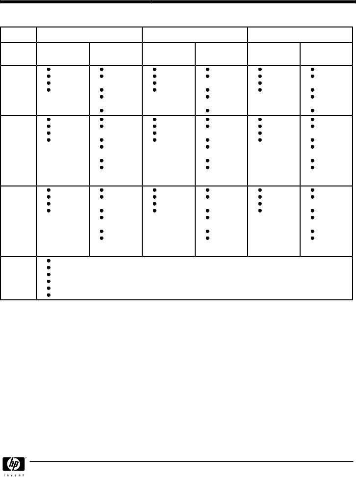
Standard Features
System |
HP UX 11i version 2 |
Windows Server 2003 Datacenter |
Linux |
|||
|
|
|
edition |
|
|
|
|
Minimum |
Maximum |
Minimum |
Maximum |
Minimum |
Maximum |
|
|
(in one partition) |
|
(in one |
|
(in one partition) |
|
|
|
|
partition) |
|
|
Superdome |
2 CPUs |
16 CPUs |
2 CPUs |
16 CPUs |
2 CPUs |
8 CPUs |
16-way |
2 GB Memory |
128 GB |
2 GB Memory |
128 GB |
2 GB Memory |
64 GB |
|
1 Cell Board |
Memory |
1 Cell Board |
Memory |
1 Cell Board |
Memory |
|
1 PCI X |
4 Cell Boards |
1 PCI X |
4 Cell Boards |
1 PCI X |
2 Cell Boards |
|
Chassis |
4 PCI X |
Chassis |
4 PCI X |
Chassis |
1 PCI X |
|
|
Chassis |
|
Chassis |
|
Chassis |
|
|
4 npars max |
|
4 npars max |
|
4 npars max |
Superdome |
2 CPUs |
32 CPUs |
2 CPUs |
32 CPUs |
2 CPUs |
8 CPUs |
32-way |
2 GB Memory |
256 GB |
2 GB Memory |
256 GB |
2 GB Memory |
64 GB |
|
1 Cell Board |
Memory |
1 Cell Board |
Memory |
1 Cell Board |
Memory |
|
1 PCI X |
8 Cell Boards |
1 PCI X |
8 Cell Boards |
1 PCI X |
2 Cell Boards |
|
Chassis |
8 PCI X |
Chassis |
8 PCI X |
Chassis |
1 PCI X |
|
|
Chassis |
|
Chassis |
|
Chassis |
|
|
8 npars max |
|
8 npars max |
|
8 npars max |
|
|
IOX required if |
|
IOX required if |
|
IOX required if |
|
|
more than 4 |
|
more than 4 |
|
more than 4 |
|
|
npars. |
|
npars. |
|
npars |
Superdome |
6 CPUs |
64 CPUs |
6 CPUs |
64 CPUs |
6 CPUs |
8 CPUs |
64-way |
6 GB memory |
512 GB |
6 GB memory |
512 GB |
6 GB memory |
64 GB |
|
3 Cell Boards |
Memory |
3 Cell Boards |
Memory |
3 Cell Boards |
Memory |
|
1 PCI X |
16 Cell Boards |
1 PCI X |
16 Cell Boards |
1 PCI X |
2 Cell Boards |
|
Chassis |
16 PCI X |
Chassis |
16 PCI X |
Chassis |
1 PCI X |
|
|
Chassis |
|
Chassis |
|
Chassis |
|
|
16 npars max |
|
16 npars max |
|
16 npars max |
|
|
IOX required if |
|
IOX required if |
|
IOX required if |
|
|
more than 8 |
|
more than 8 |
|
more than 8 |
|
|
npars. |
|
npars. |
|
npars. |
Standard |
Redundant Power supplies |
|
|
|
|
|
Hardware |
Redundant Fans |
|
|
|
|
|
Features |
Factory integration of memory and I/O cards |
|
|
|
||
|
Installation Guide, Operator's Guide and Architecture Manual |
|
|
|
||
|
HP site planning and installation |
|
|
|
|
|
|
One year warranty with same business day on site service response |
|
|
|||
DA - 11717 Worldwide — Version 1 — June 30, 2003 |
Page 4 |

QuickSpecs
HP Integrity Superdome Servers: 16-way, 32-way,
and 64-way
Configuration
There are three basic building blocks in the Superdome system architecture: the cell, the crossbar backplane and the PCI X based I/O subsystem.
Cabinets |
Starting with the sx1000 chip set, Superdome servers will be released with the Graphite color. A Superdome system will |
|
consist of up to four different types of cabinet assemblies: |
|
One Superdome left cabinet. |
|
No more than one Superdome right cabinet (only Superdome 64-way system) |
|
The Superdome cabinets contain all of the processors, memory and core devices of the system. They will also house |
|
most (usually all) of the system's PCI X cards. Systems may include both left and right cabinet assemblies |
|
containing, a left or right backplane respectively. |
|
One or more HP Rack System/E cabinets. These 19-inch rack cabinets are used to hold the system peripheral |
|
devices such as disk drives. |
|
Optionally, one or more I/O expansion cabinets (Rack System/E). An I/O expansion cabinet is required when a |
|
customer requires more PCI X cards than can be accommodated in their Superdome cabinets. |
|
Superdome cabinets will be serviced from the front and rear of the cabinet only. This will enable customers to arrange the |
|
cabinets of their Superdome system in the traditional row fashion found in most computer rooms. The width of the cabinet |
|
will accommodate moving it through common doorways in the U.S. and Europe. The intake air to the main (cell) card |
|
cage will be filtered. This filter will be removable for cleaning/replacement while the system is fully operational. |
|
A status display will be located on the outside of the front and rear doors of each cabinet. The customer and field engineers |
|
can therefore determine basic status of each cabinet without opening any cabinet doors. |
|
Superdome 16-way and Superdome 32-way systems are available in single cabinets. Superdome 64 way systems are |
|
available in dual cabinets. |
|
Each cabinet may contain a specific number of cell boards (consisting of CPUs and memory) and I/O. See the following |
|
sections for configuration rules pertaining to each cabinet. |
|
|
Cells (CPUs and Memory) A cell, or cell board, is the basic building block of a Superdome system. It is a symmetric multi processor (SMP), containing up to 4 processor modules and up to 16 GB of main memory using 512 MB DIMMs or up to 32 GB of main memory using 1 GB DIMMs. It is also possible to mix 512 MB and 1 GB DIMMs on the same cell board. A connection to a 12 slot PCI X card cage is optional for each cell.
The Superdome cell boards shipped from the factory are offered with 2 processors or 4 processors. These cell boards are different from those that were used in the previous releases of Superdome.
The cell boards can contain a minimum of 2 (for 2-way cell boards) and 4 (for 4-way cell boards) active processors.
The Superdome cell board contains:
|
Itanium 2 1.5-GHz CPUs (up to 4 processor modules) |
|
Cell controller ASIC (application specific integrated circuit) |
|
Main memory DIMMs (up to 32 DIMMs per board in 4 DIMM increments, using 512 MB or 1 GB DIMMs - or some |
|
combination of both.) |
|
Voltage Regulator Modules (VRM) |
|
Data buses |
|
Optional link to 12 PCI X I/O slots |
|
|
Crossbar Backplane |
Each crossbar backplane contains two sets of two crossbar chips that provide a non blocking connection between eight |
|
cells and the other backplane. Each backplane cabinet can support up to eight cells or 32 processors (in a Superdome 32- |
|
way in a single cabinet). A backplane supporting four cells or 16 processors would result in a Superdome 16-way. Two |
|
backplanes can be linked together with flex cables to produce a cabinet that can support up to 16 cells or 64 processors |
|
(Superdome 64-way in dual cabinets). |
|
|
DA - 11717 Worldwide — Version 1 — June 30, 2003 |
Page 5 |

QuickSpecs
HP Integrity Superdome Servers: 16-way, 32-way,
and 64-way
Configuration
I/O Subsystem |
Each I/O chassis provides twelve PCI X slots; eight standard and four high bandwidth PCI X slots. There are two I/O chassis |
|
|
in an I/O Chassis Enclosure (ICE). Each I/O chassis connects to one cell board and the number of I/O chassis supported is |
|
|
dependent on the number of cells present in the system. If a PCI card is inserted into a PCI X slot, the card cannot take |
|
|
advantage of the faster slot. |
|
|
Each Superdome cabinet supports a maximum of four I/O chassis. The optional I/O expansion cabinet can support up to |
|
|
six I/O chassis. |
|
|
A 4 cell Superdome (16-way) supports up to four I/O chassis for a maximum of 48 PCI X slots. |
|
|
An 8 cell Superdome supports up to eight I/O chassis for a maximum of 96 PCI X slots. Four of these I/O chassis will reside |
|
|
in an I/O expansion cabinet. |
|
|
A 16-cell Superdome supports up to sixteen I/O chassis for a maximum of 192 PCI X slots. Eight of these I/O chassis will |
|
|
reside in two I/O expansion cabinets (either six chassis in one I/O expansion cabinet and two chassis in the other, or four |
|
|
chassis in each). |
|
|
|
|
Core I/O |
The core I/O in Superdome provides the base set of I/O functions required by every Superdome partition. Each partition |
|
|
must have at least one core I/O card in order to boot. Multiple core I/O cards may be present within a partition (one core |
|
|
I/O card is supported per I/O backplane); however, only one may be active at a time. Core I/O will utilize the standard |
|
|
long card PCI X form factor but will add a second card cage connection to the I/O backplane for additional non PCI X |
|
|
signals (USB and utilities). This secondary connector will not impede the ability to support standard PCI X cards in the core |
|
|
slot when a core I/O card is not installed. |
|
|
Any I/O chassis can support a Core I/O card that is required for each independent partition. A system configured with 16 |
|
|
cells, each with its own I/O chassis and core I/O card could support up to 16 independent partitions. Note that cells can |
|
|
be configured without I/O chassis attached, but I/O chassis cannot be configured in the system unless attached to a cell. |
|
|
|
|
HP-UX Core I/O |
The core I/O card's primary functions are: |
|
(A6865A) |
|
|
|
Partitions (console support) including USB and RS 232 connections |
|
|
10/100Base T LAN (general purpose) |
|
|
Other common functions, such as Ultra/Ultra2 SCSI, Fibre Channel, and Gigabit Ethernet, are not included on the core I/O |
|
|
card. These functions are, of course, supported as normal PCI X add in cards. |
|
|
The unified 100Base T Core LAN driver code searches to verify whether there is a cable connection on an RJ 45 port or on an |
|
|
AUI port. If no cable connection is found on the RJ 45 port, there is a busy wait pause of 150 ms when checking for an AUI |
|
|
connection. By installing the loopback connector (description below) in the RJ 45 port, the driver would think an RJ 45 cable |
|
|
was connected and would not continue to search for an AUI connection, hence eliminate the 150 ms busy wait state: |
|
|
|
|
|
Product/ |
Description |
|
Option Number |
|
|
|
|
|
|
|
|
A7108A |
RJ 45 Loopback Connector |
|
|
|
|
|
|
|
0D1 |
Factory integration RJ 45 Loopback Connector |
|
|
|
|
|
|
Windows Core I/O For Windows Server 2003, two core I/O cards are required: the Superdome core I/O card (A6865A) and a 1000Base T LAN (A6865A and A7061A and card (A7061A). The use of Graphics/USB card (A6869A) is optional and not required.
optional VGA/USB A6869A)
DA - 11717 Worldwide — Version 1 — June 30, 2003 |
Page 6 |

QuickSpecs
HP Integrity Superdome Servers: 16-way, 32-way,
and 64-way
Configuration
I/O Expansion Cabinet |
The I/O expansion functionality is physically partitioned into four rack mounted chassis-the I/O expansion utilities chassis |
|
(XUC), the I/O expansion rear display module (RDM), the I/O expansion power chassis (XPC) and the I/O chassis enclosure |
|
(ICE). Each ICE supports up to two 12-slot PCI-X chassis. |
|
|
Field Racking |
The only field rackable I/O expansion components are the ICE and the 12-slot I/O chassis. Either component would be |
|
field installed when the customer has ordered additional I/O capability for a previously installed I/O expansion cabinet. |
|
No I/O expansion cabinet components will be delivered to be field installed in a customer's existing rack other than a |
|
previously installed I/O expansion cabinet. The I/O expansion components were not designed to be installed in racks other |
|
than Rack System E. In other words, they are not designed for Rosebowl I, pre merger Compaq, Rittal, or other third party |
|
racks. |
|
The I/O expansion cabinet is based on a modified HP Rack System E and all expansion components mount in the rack. |
|
Each component is designed to install independently in the rack. The Rack System E cabinet has been modified to allow |
|
I/O interface cables to route between the ICE and cell boards in the Superdome cabinet. I/O expansion components are |
|
not designed for installation behind a rack front door. The components are designed for use with the standard Rack System |
|
E perforated rear door. |
|
|
I/O Chassis Enclosure |
The I/O chassis enclosure (ICE) provides expanded I/O capability for Superdome. Each ICE supports up to 24 PCI-X slots |
(ICE) |
by using two 12-slot Superdome I/O chassis. The I/O chassis installation in the ICE puts the PCI-X cards in a horizontal |
|
position. An ICE supports one or two 12-slot I/O chassis. The I/O chassis enclosure (ICE) is designed to mount in a Rack |
|
System E rack and consumes 9U of vertical rack space. |
|
To provide online addition/replacement/deletion access to PCI or PCI-X cards and hot swap access for I/O fans, all I/O |
|
chassis are mounted on a sliding shelf inside the ICE. |
|
Four (N+1) I/O fans mounted in the rear of the ICE provide cooling for the chassis. Air is pulled through the front as well |
|
as the I/O chassis lid (on the side of the ICE) and exhausted out the rear. The I/O fan assembly is hot swappable. An LED |
|
on each I/O fan assembly indicates that the fan is operating. |
|
|
Cabinet Height and Although the individual I/O expansion cabinet components are designed for installation in any Rack System E cabinet, Configuration Limitations rack size limitations have been agreed upon. IOX Cabinets will ship in either the 1.6 meter (33U) or 1.96 meter (41U)
cabinet. In order to allay service access concerns, the factory will not install IOX components higher than 1.6 meters from the floor. Open space in an IOX cabinet will be available for peripheral installation.
Peripheral Support |
All peripherals qualified for use with Superdome and/or for use in a Rack System E are supported in the I/O expansion |
|
cabinet as long as there is available space. Peripherals not connected to or associated with the Superdome system to which |
|
the I/O expansion cabinet is attached may be installed in the I/O expansion cabinet. |
|
|
Server Support |
No servers except those required for Superdome system management such as Superdome Support Management Station or |
|
ISEE may be installed in an I/O expansion. |
|
Peripherals installed in the I/O expansion cabinet cannot be powered by the XPC. Provisions for peripheral AC power must |
|
be provided by a PDU or other means. |
|
|
Standalone I/O Expansion If an I/O expansion cabinet is ordered alone, its field installation can be ordered via option 750 in the ordering guide Cabinet (option 950 for Platinum Channel partners).
DA - 11717 Worldwide — Version 1 — June 30, 2003 |
Page 7 |

QuickSpecs
HP Integrity Superdome Servers: 16-way, 32-way,
and 64-way
Configuration
DVD Solution |
The DVD solution for Superdome requires the following components. These components are recommended per partition, |
|
although it is acceptable to have only one DVD solution and connect it to one partition at a time. External racks A4901A |
|
and A4902A must also be ordered with the DVD solution. |
Superdome DVD Solutions
Description |
Part Number |
Option Number |
|
|
|
|
|
|
|
|
|
PCI Ultra160 SCSI Adapter or PCI-X Dual channel Ultra160 SCSI Adapter |
A6828A or A6829A |
0D1 |
|
|
|
|
|
|
|
|
|
PCI Ultra160 SCSI Adapter or PCI-X Dual channel Ultra 160 SCSI Adapter |
A7059A or A7060A |
0D1 |
|
(Windows Server 2003) |
|||
|
|
||
|
|
|
|
|
|
|
|
Surestore Tape Array 5300 |
C7508AZ |
|
|
|
|
|
|
|
|
|
|
DVD (recommend one per partition) |
C7499A |
0D1 |
|
|
|
|
|
|
|
|
|
DDS-4 (opt.)/DAT40 (DDS-5/DAT 72 is also supported. Product number is |
C7497A |
0D1 |
|
Q1524A) |
|||
|
|
||
|
|
|
|
|
|
|
|
Jumper SCSI Cable for DDS-4 (optional) 1 |
C2978B |
0D1 |
|
|
|
|
|
SCSI Cable 2,3 |
C2363B 2 |
0D1 |
|
|
|
|
|
SCSI Terminator |
C2364A |
0D1 |
|
|
|
|
|
|
|
|
1.0.5-meter HD HDTS68 is required if DDS-4 is used.
2.5-meter multi-mode VH-HD68TS available now (C2365B #0D1) and can be used in place of the 10meter cable on solutions that will be physically compact
3.10-meter multi-mode VH-HD68TS available now (C2363B, #0D1)
Partitions |
Superdome can be configured with hardware partitions, (npars). Given that HP-UX 11i version 2 does not support virtual |
|
partitions (vpars), Superdome systems running HP-UX 11i version 2 do not support vpars. |
|
A hardware partition (npar) consists of one or more cells that communicate coherently over a high bandwidth, low latency |
|
crossbar fabric. Individual processors on a single-cell board cannot be separately partitioned. Hardware partitions are |
|
logically isolated from each other such that transactions in one partition are not visible to the other hardware partitions |
|
within the same complex. |
|
Each npar runs its own independent operating system. Different npars may be executing the same or different revisions of an |
|
operating system, or they may be executing different operating systems altogether. Superdome supports HP-UX 11i version 2 |
|
(at first release), Windows Server 2003 (at first release + 2 to 4 months) and Linux (first release + 6 months) operating |
|
systems. |
Each npar has its own independent CPUs, memory and I/O resources consisting of the resources of the cells that make up the partition. Resources (cell boards and/or I/O chassis) may be removed from one npar and added to another without having to physically manipulate the hardware, but rather by using commands that are part of the System Management interface. The table below shows the maximum size of npars per operating system:
|
HP UX 11i Version 2 |
Windows Server 2003 |
Red Hat Enterprise Linux |
|
|
|
AS 3 or Debian Linux |
|
|
|
|
|
|
|
|
Maximum size of npar |
64 CPUs, 512 GB RAM |
64 CPUs, 512 GB RAM |
8 CPUs, 64 GB RAM |
|
|
|
|
|
|
|
|
Maximum number of npars |
16 |
16 |
16 |
|
|
|
|
|
|
|
|
For information on type of I/O cards for networking and mass storage for each operating environment, please refer to the Technical Specifications section. For licensing information for each operating system, please refer to the Ordering Guide.
Superdome supports static partitions. Static partitions imply that any npar configuration change requires a reboot of the npar. In a future HP-UX and Windows release, dynamic npars will be supported. Dynamic npars imply that npar configuration changes do not require a reboot of the npar. Using the related capabilities of dynamic reconfiguration (i.e. online addition, on-line removal), new resources may be added to an npar and failed modules may be removed and replaced while the npar continues in operation. Adding new npars to Superdome system does not require a reboot of the system.
Single System
Reliability/Availability
Features
Superdome high availability offering is as follows:
NOTE: Online addition/replacement for cell boards is not currently supported and will be available in a future HP-UX release. Online addition/replacement of individual CPUs and memory DIMMs will never be supported.)
DA - 11717 Worldwide — Version 1 — June 30, 2003 |
Page 8 |

QuickSpecs
HP Integrity Superdome Servers: 16-way, 32-way,
and 64-way
Configuration
CPU: The features below nearly eliminate the down time associated with CPU cache errors (which are the majority of CPU errors). If a CPU is exhibiting excessive cache errors, HP-UX 11i version 2 will ONLINE activate to take its place. Furthermore, the CPU cache will automatically be repaired on reboot, eliminating the need for a service call.
Dynamic processor resilience w/ iCOD enhancement.
NOTE: Dynamic processor resilience and iCOD are not supported when running Windows Server 2003 or Linux in the partition.
CPU cache ECC protection and automatic de allocation
CPU bus parity protection
Redundant DC conversion
Memory: The memory subsystem design is such that a single SDRAM chip does not contribute more than 1 bit to each ECC word. Therefore, the only way to get a multiple bit memory error from SDRAMs is if more than one SDRAM failed at the same time (rare event). The system is also resilient to any cosmic ray or alpha particle strike because these failure modes can only affect multiple bits in a single SDRAM. If a location in memory is "bad", the physical page is de allocated dynamically and is replaced with a new page without any OS or application interruption. In addition, a combination of hardware and software scrubbing is used for memory. The software scrubber reads/writes all memory locations periodically. However, it does not have access to "locked down" pages. Therefore, a hardware memory scrubber is provided for full coverage. Finally data is protected by providing address/control parity protection.
Memory DRAM fault tolerance, i.e. recovery of a single SDRAM failure
DIMM address / control parity protection
Dynamic memory resilience, i.e. page de allocation of bad memory pages during operation.
NOTE: Dynamic memory resilience is not supported when running Windows Server 2003 or Linux in the partition.
Hardware and software memory scrubbing
Redundant DC conversion
Cell COD.
NOTE: Cell COD is not supported when Windows Server 2003 or Linux is running in the partition. I/O: Partitions configured with dual path I/O can be configured to have no shared components between them,
thus preventing I/O cards from creating faults on other I/O paths. I/O cards in hardware partitions (npars) are fully isolated from I/O cards in other hard partitions. It is not possible for an I/O failure to propagate across hard partitions. It is possible to dynamically repair and add I/O cards to an existing running partition.
Full single wire error detection and correction on I/O links
I/O cards fully isolated from each other
HW for the Prevention of silent corruption of data going to I/O
On line addition/replacement (OLAR) for individual I/O cards, some external peripherals, SUB/HUB.
Parity protected I/O paths
Dual path I/O
Crossbar and Cabinet Infrastructure:
Recovery of a single crossbar wire failure
Localization of crossbar failures to the partitions using the link
Automatic de-allocation of bad crossbar link upon boot
Redundant and hotswap DC converters for the crossbar backplane
ASIC full burn-in and "high quality" production process
Full "test to failure" and accelerated life testing on all critical assemblies
Strong emphasis on quality for multiple-nPartition single points of failure (SPOFs)
System resilience to Management Processor (MP)
Isolation of nPartition failure
Protection of nPartitions against spurious interrupts or memory corruption
Hot swap redundant fans (main and I/O) and power supplies (main and backplane power bricks)
Dual power source
Phone-Home capability
HA Cluster-In-A-Box" Configuration: The "HA Cluster-In-A- Box" allows for failover of users' applications between hardware partitions (npars) on a single Superdome system. All providers of mission critical solutions agree that failover between clustered systems provides the safest availability-no single points of failures (SPOFs) and no ability to propagate failures between systems. However, HP supports the configuration of HA cluster software in a single system to allow the highest possible availability for those users that need the benefits of a non-clustered solution, such as scalability and manageability. Superdome with this configuration will provide the greatest single system availability configurable. Since no single system solution in the industry provides protection against a SPOF, users that still need this kind of safety and HP's highest availability should use HA cluster software in a multiple system HA configuration. Multiple HA software clusters can be configured within a single Superdome system (i.e., two 4 -ode clusters configured within a 32-way Superdome system).
DA - 11717 Worldwide — Version 1 — June 30, 2003 |
Page 9 |

QuickSpecs
HP Integrity Superdome Servers: 16-way, 32-way,
and 64-way
Configuration
HP-UX: Serviceguard and Serviceguard Extension for RAC
Windows Server 2003: Microsoft Cluster Service (MSCS) - limited configurations supported
Linux: Serviceguard for Linu
Multi-system High
Availability
HP-UX 11i v2:
Any Superdome partition that is protected by Serviceguard or Serviceguard Extension for RAC can be configured in a cluster with:
Another Superdome with Itanium 2 processors
One or more standalone non Superdome systems with Itanium 2 processors
Another partition within the same single cabinet Superdome (refer to "HA Cluster in a Box" above for specific requirements)
Separate partitions within the same Superdome system can be configured as part of different Serviceguard clusters.
Geographically Dispersed HP-UX 11i v2:
Cluster Configurations
Windows Server 2003
Linux
Supportability Features
Console Access (Management Processor [MP])
DA - 11717 Worldwide — Version 1 — June 30, 2003 |
Page 10 |
QuickSpecs
HP Integrity Superdome Servers: 16-way, 32-way,
and 64-way
Configuration
access to the MP, and by its support for multiple geographically distributed console devices.
Three common data center styles are:
The secure site where both the system and its console are physically secured in a small area.
The "glass room" configuration where all the systems' consoles are clustered in a location physically near the machine room.
The geographically dispersed site, where operators administer systems from consoles in remote offices.
These can each drive different solutions to the console access requirement.
The considerations listed below apply to the design of provision of console access to the server. These must be considered during site preparation.
The Superdome server can be operated from a VT100 or an hpterm compatible terminal emulator. However some programs (including some of those used by field engineers) have a more friendly user interface when operated from an hpterm.
LAN console device users connect to the MP (and thence to the console) using terminal emulators that establish telnet connections to the MP. The console device(s) can be anywhere on the network connected to either port of the MP.
Telnet data is sent between the client console device and the MP "in the clear", i.e. unencrypted. This may be a concern for some customers, and may dictate special LAN configurations.
If an HP-UX workstation is used as a console device, an hpterm window running telnet is the recommended way to connect to the MP. If a PC is used as a console device, Reflection1 configured for hpterm emulation and telnet connection is the recommended way to connect to the MP.
The MP currently supports a maximum of 16 telnet-connected users at any one time.
It is desirable, and sometimes essential for rapid time to repair to provide a reliable way to get console access that is physically close to the server, so that someone working on the server hardware can get immediate access to the results of their actions. There are a few options to achieve this:
Place a console device close to the server.
Ask the field engineer to carry in a laptop, or to walk to the operations center.
Use a system that is already in close proximity of the server such as the Instant Support Enterprise Edition (ISEE) or the System Management Station as a console device close to the system.
The system administrator is likely to want to run X applications or a browser using the same client that they access the MP and partition consoles with. This is because the partition configuration tool, parmgr, has a graphical interface. The system administrator's console device(s) should have X window or browser capability, and should be connected to the system LAN of one or more partitions.
Functional capabilities:
Local console physical connection (RS-232)
Display of system status on the console (Front panel display messages) Console mirroring between LAN and RS-232 ports
System hard and soft (TOC or INIT) reset capability from the console. Password secured access to the console functionality
Support of generic terminals (i.e. VT100 compatible).
Power supply control and monitoring from the console. It will be possible to get power supply status and to switch power on/off from the console.
Console over the LAN. This means that a PC or HP workstation can become the system console if properly connected on the customer LAN. This feature becomes especially important because of the remote power management capability. The LAN will be implemented on a separate port, distinct from the system LAN, and provide TCP/IP and Telnet access.
There is one MP per Superdome cabinet, thus there are two (2) for Superdome 64-way. But one, and only one, can be active at a time. There is no redundancy or failover feature.
DA - 11717 Worldwide — Version 1 — June 30, 2003 |
Page 11 |

QuickSpecs
HP Integrity Superdome Servers: 16-way, 32-way,
and 64-way
Configuration
Windows |
TFor Windows Server 2003 customers desiring full visibility to the Superdome Windows partition, an IP console solution is |
|
available to view the partition while the OS is rebooting (in addition to normal Windows desktop). Windows Terminal |
|
Services (standard in Windows Server 2003) can provide remote access, but does not display VGA during reboot. For |
|
customers who mandate VGA access during reboot, the IP console switch (262586-B21), used in conjunction with a |
|
VGA/USB card in the partition (A6869A) is the solution. |
|
In order to have full graphical console access when running Windows Server 2003 on Superdome, the 3×1×16 IP Console |
|
Switch (product number 262586-B21) is required. |
|
The features of this switch are as follows: |
|
Provides keyboard, video and mouse (KVM) connections to 16 direct attached Windows partitions (or servers) - |
|
expandable to 128. |
|
Allows access to partitions (or servers) from a remote centralized console. |
|
1 for local KVM |
|
3 concurrent remote users (secure SSL data transfer across network) |
|
Single screen switch management with the IP Console Viewer Software: |
|
Authentication |
|
Administration |
|
Client Software |
If the full graphical console access is needed, the following must be ordered.
Component |
Product Number |
|
|
|
|
3×1×16 IP console switch (100 240V)-1 switch per 16 OS instances (n<=16), each connected to |
262586-B21 |
VGA card |
|
|
|
|
|
8 to 1 console expander-Order expander if there are more than 16 OS instances |
262589-B21 |
|
|
|
|
USB interface adapters-Order one per OS instance |
336057-001 |
|
|
|
|
CAT5 cable-Order one per OS instance |
C7542A |
|
|
|
|
AB243A 1U KVM-For local KVM - provides a full 15" digital display, keyboard, mouse and console |
221546-B21 |
switch in only 1U |
|
|
|
|
|
Support Management The purpose of the Support Management Station (SMS) is to provide Customer Engineers with an industry-leading set of Station support tools, and thereby enable faster troubleshooting and more precise problem root cause analysis. It also enables
remote support by factory experts who consult with and back up the HP Customer Engineer. The SMS complements the proactive role of HP's Instant Support Enterprise Edition (ISEE) (which is offered to Mission Critical customers), by focusing on reactive diagnosis, for both mission critical and non mission critical Superdome customers.
The user of the SMS is the HP Customer Engineer and HP Factory Support Engineer. The Superdome customer benefits from their use of the SMS by receiving faster return to normal operation of their Superdome server, and improved accuracy of fault diagnosis, resulting in fewer callbacks. HP can offer better service through reduced installation time.
Only one SMS is required per customer site (or data center) connected to each platform via Ethernet LAN. Physically, it would be beneficial to have the SMS close to the associated platforms because the customer engineer will run the scan tools and would need to be near platform to replace failing hardware. The physical connection from the platform is an Ethernet connection and thus, the absolute maximum distance is not limited by physical constraints.
The SMS supports a single LAN interface that is connected to the Superdome and to the customer's management LAN.
When connected in this manner, SMS operations can be performed remotely.
Physical Connection:
The SMS will contain one physical Ethernet connection, namely a 10/100Base-T connection. Note that the connection on Superdome (MP) is also 10/100Base-T, as is the LAN connection on the core I/O card installed in each hardware partition.
For connecting more than one Superdome server to the SMS, a LAN hub is required for the RJ-45 connection. A point to point connection is only required for one Superdome server to one SMS.
DA - 11717 Worldwide — Version 1 — June 30, 2003 |
Page 12 |
Loading...