


 Loading...
HP Indigo 7000 Digital Press
User Guide

HP Indigo 7000 Digital Press
User guide
© 2008 Copyright Hewlett-Packard
Development Company, L.P.
Reproduction, adaptation, or translation without prior written permission is prohibited, except as allowed under the copyright laws.
The information contained herein is subject to change without notice.
The only warranties for HP products and services are set forth in the express warranty statements accompanying such products and services. Nothing herein should be construed as constituting an additional warranty. HP shall not be liable for technical or editorial errors or omissions contained herein.
HP, HP Indigo Press, HP Indigo Press RIP, and HP ElectroInk are trademarks or registered trademarks of HP.
Adobe® PostScript® is a trademark of Adobe Systems Incorporated.
MS Windows® and Windows® are U.S. registered trademarks of Microsoft Corp.
All other products or name brands are trademarks of their respective holders.
The HP Indigo press' counter feature records the number of impressions you make using your press. The counter does not reflect any previous use of the press or its age.
The HP Indigo press is a Class 1 Laser Product containing high voltage power supplies and laser light sources. There is no danger to persons or equipment when the system is operated in accordance with the directions provided by HP in this and other publications. All high voltage power supplies and laser sources are located behind protective covers. Warning labels are attached to each protective cover. Do not remove covers.
Part Number: CA394-00180
First Edition: May 2008

Table of contents
1 About this user guide |
|
Overview .............................................................................................................................................. |
2 |
Conventions used in this guide ............................................................................................................ |
4 |
2 Product overview |
|
HP Indigo press .................................................................................................................................... |
6 |
HP Indigo 7000 Digital Press ............................................................................................... |
6 |
Press serial number ............................................................................................................. |
7 |
General press specifications ................................................................................................................ |
8 |
Printing rate ......................................................................................................................... |
8 |
3 Safety |
|
Overview ............................................................................................................................................ |
10 |
Warning signs and labels ................................................................................................................... |
11 |
Warning labels on the press .............................................................................................. |
11 |
Warning signs .................................................................................................................... |
12 |
Placement of warning labels .............................................................................................. |
13 |
Safety devices .................................................................................................................................... |
14 |
Material safety data sheets (MSDS) .................................................................................. |
14 |
Fire extinguishing equipment ............................................................................................. |
14 |
Eye wash stations .............................................................................................................. |
14 |
Noise levels ....................................................................................................................... |
14 |
Heat insulating tools .......................................................................................................... |
14 |
Electrical safety .................................................................................................................. |
14 |
Emergency power shutdown .............................................................................................................. |
16 |
Door interlocks and warning indicators .............................................................................................. |
19 |
Door interlocks ................................................................................................................... |
19 |
Attention lights .................................................................................................................................... |
21 |
Maintenance safety and emergency procedures ............................................................................... |
23 |
Standby status ................................................................................................................... |
23 |
Inching button .................................................................................................................... |
23 |
Inch-safe method ............................................................................................................... |
23 |
Press lockout procedure .................................................................................................... |
24 |
Combustible and flammable liquids and fumes .................................................................................. |
25 |
ENWW |
iii |
Isopropyl alcohol (IPA) ....................................................................................................... |
25 |
Handling and storing imaging oil, inks, and IPA ................................................................ |
25 |
Disposing of consumables and cleaning materials ............................................................ |
25 |
Waste bottles ..................................................................................................................... |
26 |
Additional information ........................................................................................................ |
27 |
4 Operating the press |
|
Turning the press on .......................................................................................................................... |
30 |
Using the press .................................................................................................................................. |
31 |
Using the control panel ....................................................................................................................... |
32 |
Using the software ............................................................................................................. |
32 |
The control panel .............................................................................................. |
32 |
Small press schematic ...................................................................... |
32 |
Print job panel ................................................................................... |
33 |
Main toolbar ...................................................................................... |
34 |
Print controls ..................................................................................... |
34 |
Working area ..................................................................................................... |
37 |
Navigating in the working area ......................................................... |
37 |
Virtual keyboards .............................................................................................. |
37 |
Turning the press off .......................................................................................................................... |
38 |
5 Job handling |
|
Managing jobs .................................................................................................................................... |
40 |
Print Queue ........................................................................................................................ |
40 |
Printing jobs ........................................................................................................................................ |
41 |
Stage 1: Loading jobs ........................................................................................................ |
41 |
Stage 2: Proofing ............................................................................................................... |
41 |
Stage 3: Printing the full run .............................................................................................. |
42 |
Job maintenance ................................................................................................................................ |
43 |
Job disposition and retrieval .............................................................................................. |
43 |
Editing job properties ......................................................................................................... |
43 |
Image placement ............................................................................................................... |
44 |
Editing job look-up tables (LUTs) ....................................................................................... |
46 |
Screening ........................................................................................................................... |
48 |
Inks “double-hit” printing .................................................................................................... |
49 |
Linework and resolution ..................................................................................................... |
50 |
6 Color management |
|
Calibrating the press colors ................................................................................................................ |
54 |
Color Calibration procedures .............................................................................................................. |
55 |
Defining substrate-related color parameters ...................................................................................... |
57 |
Optical density of substrates .............................................................................................. |
57 |
Selecting a workflow for full color calibration and substrate-related parameters ............................... |
59 |
iv |
ENWW |
Very high accuracy workflow ............................................................................................. |
59 |
High accuracy workflow ..................................................................................................... |
59 |
Normal accuracy workflow ................................................................................................. |
59 |
Viewing last color calibration generation ........................................................................... |
60 |
Determining substrate type ................................................................................................ |
60 |
7 Substrate handling system |
|
Overview ............................................................................................................................................ |
66 |
Substrate specifications ..................................................................................................................... |
67 |
Grain direction ................................................................................................................... |
67 |
Sheet trimming ................................................................................................................... |
68 |
Sheet size .......................................................................................................................... |
68 |
Loading substrate into the feeder ....................................................................................................... |
69 |
Monitoring status of substrates in drawers ......................................................................................... |
70 |
Defining substrate type ....................................................................................................................... |
71 |
Operating and unloading the stacker ................................................................................................. |
73 |
Unloading a substrate stack .............................................................................................. |
74 |
Defining stacker options ..................................................................................................................... |
76 |
Adjusting stacker options ................................................................................................... |
76 |
Clearing substrate jams ...................................................................................................................... |
78 |
Removing a substrate jam at the external heating housing ............................................... |
79 |
Maintaining the substrate transport system ........................................................................................ |
84 |
Cleaning the substrate path ............................................................................................... |
84 |
8 Operator routines |
|
Maintenance routines ......................................................................................................................... |
88 |
Using the maintenance routine checklists ......................................................................... |
88 |
Configuration file backup ................................................................................... |
88 |
Practical tips for performing maintenance routines ............................................................ |
89 |
Protecting substrate .......................................................................................... |
89 |
IPA contamination ............................................................................................. |
89 |
Water contamination ......................................................................................... |
90 |
PIP protection .................................................................................................... |
90 |
Lubricating the mechanical system .................................................................................................... |
91 |
Replacing the lubrication can ............................................................................................. |
91 |
9 Ink system |
|
Overview ............................................................................................................................................ |
94 |
Replacing ink cans ............................................................................................................................. |
95 |
Rebuilding the ink in a tank ................................................................................................................ |
96 |
Draining ink tanks ............................................................................................................................... |
98 |
Cleaning the ink pumps ...................................................................................................................... |
99 |
ENWW |
v |
10 Binary ink developer (BID) |
|
Overview .......................................................................................................................................... |
104 |
Replacing the BID ............................................................................................................................ |
106 |
Removing a BID ............................................................................................................... |
106 |
Installing a new BID ......................................................................................................... |
107 |
Returning a BID ............................................................................................................... |
109 |
Adjusting the BID engage and disengage angle .............................................................................. |
110 |
11 Blanket |
|
Overview .......................................................................................................................................... |
118 |
Replacing the blanket ....................................................................................................................... |
119 |
Removing the old blanket ................................................................................................ |
119 |
Installing a new blanket ................................................................................................... |
121 |
Cleaning the blanket ......................................................................................................................... |
122 |
Using the Print Cleaner wizard ........................................................................................ |
122 |
Manually cleaning the blanket ......................................................................................... |
122 |
Recovering the blanket surface ....................................................................................... |
122 |
Using the automatic blanket cleaner page ....................................................................... |
123 |
First transfer calibration .................................................................................................................... |
125 |
Calibrating the pressure ................................................................................................... |
125 |
Cleaning the ITM area ...................................................................................................................... |
128 |
12 PIP |
|
Overview .......................................................................................................................................... |
130 |
Replacing the PIP Foil ...................................................................................................................... |
131 |
Removing the old PIP foil ................................................................................................ |
131 |
Installing a new PIP foil .................................................................................................... |
131 |
Replacing the PIP underlayer ........................................................................................................... |
133 |
Removing the old PIP underlayer .................................................................................... |
133 |
Cleaning the PIP drum ..................................................................................................... |
133 |
Installing the new PIP underlayer .................................................................................... |
134 |
13 Impression drum |
|
Overview .......................................................................................................................................... |
140 |
Replacing the impression paper ....................................................................................................... |
141 |
Cleaning the grippers ....................................................................................................................... |
143 |
14 Imaging oil |
|
Overview .......................................................................................................................................... |
146 |
Refilling the imaging oil tank ............................................................................................................. |
147 |
Adding recycling agent ..................................................................................................................... |
148 |
Replacing the imaging oil filters ........................................................................................................ |
150 |
Cleaning the imaging oil cleanness sensor ...................................................................................... |
152 |
vi |
ENWW |
15 |
Utility cabinet |
|
|
Overview .......................................................................................................................................... |
156 |
|
Draining water and process oily waste ............................................................................................. |
157 |
|
Draining the oil-water separator ....................................................................................................... |
159 |
16 |
Cleaning station |
|
|
Overview .......................................................................................................................................... |
162 |
|
Cleaning the cleaning station blade ................................................................................................. |
163 |
|
Rotating and replacing the cleaning station blade ............................................................................ |
165 |
|
Removing the cleaning station ......................................................................................... |
165 |
|
Installing the cleaning station ........................................................................................... |
166 |
|
Replacing the sponge roller .............................................................................................................. |
167 |
17 Charge Roller Assembly |
|
|
|
Overview .......................................................................................................................................... |
172 |
|
Charge roller maintenance procedures ............................................................................................ |
173 |
|
Removing and replacing the charge roller ....................................................................... |
173 |
|
Replacing the charge roller .............................................................................................. |
173 |
|
Replacing the carbon brushes ......................................................................................... |
174 |
|
Cleaning the charge roller ............................................................................................... |
175 |
18 |
Pre-transfer erase (PTE) |
|
|
Overview .......................................................................................................................................... |
178 |
|
Cleaning the PTE ............................................................................................................................ |
179 |
19 |
Exit Roller |
|
|
Overview .......................................................................................................................................... |
182 |
|
Cleaning the exit roller ...................................................................................................................... |
183 |
20 |
Pre-heater |
|
|
Overview .......................................................................................................................................... |
186 |
|
Removing the pre-heater housing .................................................................................................... |
187 |
21 Chiller Operation and Maintenance |
|
|
|
Overview .......................................................................................................................................... |
190 |
|
Chiller type ....................................................................................................................... |
190 |
|
Warnings .......................................................................................................................................... |
191 |
|
Operating conditions ........................................................................................................................ |
192 |
|
Control panel .................................................................................................................................... |
193 |
|
Components of the control panel ..................................................................................... |
193 |
|
Control thermostat ........................................................................................................... |
194 |
|
Maintenance ..................................................................................................................................... |
196 |
ENWW |
vii |
Weekly ............................................................................................................................. |
196 |
Monthly ............................................................................................................................ |
196 |
Yearly ............................................................................................................................... |
196 |
Appendix A Supplies and jigs |
|
Imaging supplies .............................................................................................................................. |
198 |
User maintenance supplies .............................................................................................................. |
199 |
User tools and jigs ............................................................................................................................ |
200 |
General supplies .............................................................................................................................. |
201 |
Accessories ..................................................................................................................... |
201 |
Substrate treatment ......................................................................................................... |
201 |
Appendix B Service and support |
|
Glossary ........................................................................................................................................................... |
205 |
Index ................................................................................................................................................................. |
209 |
viii |
ENWW |

1 About this user guide
Welcome to the HP Indigo 7000 Digital Press. This preface provides an overview of the user guide contents and explains conventions used in this guide.
This preface contains the following sections:
●Overview
●Conventions used in this guide
ENWW |
1 |
Overview
This user guide assumes that you are familiar with the basic Windows environment and that you have basic Windows skills, such as using a mouse and selecting menu items. If you do not, please see the Windows documentation that came with the computer.
This user guide also assumes that you have participated in the HP Indigo press operator course, and are familiar with the printing process.
The user guide contains the following information:
●About this user guide: Provides an overview of the user guide contents and explains conventions used in this guide.
●Product overview: Provides an overview and specifications of the HP Indigo 7000 Digital Press.
●Safety: Provides important safety information for using the HP Indigo 7000 Digital Press.
●Operating the press: Provides an overview of press operations basics.
●Job handling: Describes the job management and maintenance process on the press.
●Color management: Describes the color management and adjustment procedures.
●Substrate handling system: Describes loading, unloading, adjustment and maintenance of the substrate transport system.
●Operator routines: Provides an overview and practical tips for performing operator maintenance routines and mechanical system lubrication.
●Ink system: Describes replacement and maintenance of the HP ElectroInk system.
●Binary ink developer (BID): Provides BID maintenance and replacement procedures.
●Blanket: Describes replacement and maintenance of the blanket.
●PIP: Describes PIP replacement procedures.
●Impression drum: Describes the impression paper replacement procedure.
●Imaging oil: Describes maintenance and replacement procedures for the imaging oil system.
●Utility cabinet: Provides utility cabinet maintenance procedures.
●Cleaning station: Describes the cleaning station maintenance procedures.
●Charge Roller: Describes the charge roller maintenance procedures.
●Pre-transfer erase (PTE): Describes PTE maintenance procedures.
●Exit roller: Describes exit roller cleaning and maintenance procedures.
●Pre-heater: Describes pre-heater element cleaning and housing removal procedures.
●Chiller Operation and Maintenance: Provides inspection and maintenance procedures for the press chiller.
●Glossary: Provides definitions of terms used throughout the HP Indigo 7000 Digital Press documentation set.
2 Chapter 1 About this user guide |
ENWW |
●Supplies and jigs: Provides information on the press imaging, maintenance, and general supplies.
●Service and support: Provides customer care center service and support contact information.
ENWW |
Overview 3 |
Conventions used in this guide
This guide uses the following documentation conventions:
●Elements in the graphical user interface (GUI) which you must select or click, are indicated in bold type, for example: On the File menu, click New.
●Other elements in the GUI, such as Window names, appear in italics. For example: After selecting the options in the Print window, click OK.
●References to other sections in the guide appear in quotes, for example: See the “Installation” on page 37.
4 Chapter 1 About this user guide |
ENWW |

2 Product overview
This chapter contains the following sections:
●HP Indigo press
●General press specifications
ENWW |
5 |
HP Indigo press
The HP Indigo 7000 Digital Press is a sheet-fed digital offset color press that incorporates the patented HP ElectroInk liquid ink technology and high-speed electronic imaging to produce fully-finished, highquality color prints. The press features an intuitive and user-friendly interface, provides diagnostic screens that take the guess work out of printing.
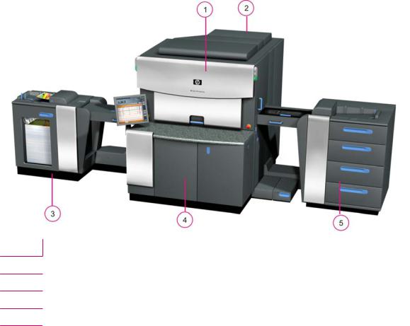
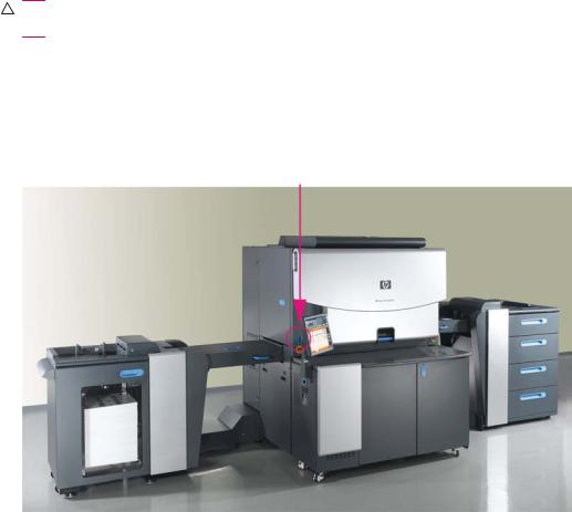
HP Indigo 7000 Digital Press
The press consists of five basic elements: the printing engine, ink cabinet, utility cabinet, feeder, and stacker.
Figure 2-1 HP Indigo 7000 Digital Press
1Printing engine
2Utility cabinet
3Stacker
4Ink cabinet
5Feeder
6 Chapter 2 Product overview |
ENWW |
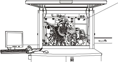
Press serial number
The press serial number is on the front of the press behind the front door.
Figure 2-2 Press serial number
7000_PREIPH-1-07
ENWW |
HP Indigo press 7 |

General press specifications
Printing rate
Input job definition |
Press productivity |
|
|
|
|
Job type1 |
A4 pages/hour |
Separations/hour (impressions/hour) |
A4 (1/0) |
14,400 |
7,200 |
|
|
|
A4 (4/0) |
7,200 |
14,400 |
|
|
|
A4 (1/1) |
7,200 |
7,200 |
|
|
|
A4 (4/4) |
3,600 |
14,400 |
1 (number of color separations on side 1 / number of color separations on side 2)
Color
Up to seven colors are supported:
●Option 1 - four process colors (CMYK - cyan, magenta, yellow, and black), plus 3 spot colors.
●Option 2 - HP IndiChrome process (six color process), plus 1 spot color.
8 Chapter 2 Product overview |
ENWW |

3 Safety
This chapter contains the following sections:
●Overview
●Warning signs and labels
●Safety devices
●Emergency power shutdown
●Door interlocks and warning indicators
●Attention lights
●Maintenance safety and emergency procedures
●Combustible and flammable liquids and fumes
ENWW |
9 |

Overview
The safety information and procedures described in this chapter apply to operators and other personnel working on or near the HP Indigo 7000 Digital Press. The safety procedures cover the press and the area immediately surrounding the press.
Use the following guidelines:
●The press must only be operated by personnel trained by HP or its authorized agents who are thoroughly familiar with all the safety and maintenance procedures of the press.
●Before you attempt to use the press, read and understand the safety procedures, including environmental protection procedures.
 NOTE: Call a customer care center for service and repair of the press. Do not attempt to service or repair the press.
The HP Indigo 7000 Digital Press is NRTL approved and marked for use in the USA and Canada.
Notice for the European Union:
This product complies with the following EU directives:
●The Low Voltage Directive 2006/95/EC
●The Machinery Directives 2006/42/EC
●The EMC Directives 2004/108/EC
Compliance with these directives implies conformity to applicable harmonized European standards (European Norms) which are listed on the Declaration of Conformity issued by Hewlett-Packard for this product or product family.
The Declaration of Conformity can be found at www.hp.com/go/certificates
10 Chapter 3 Safety |
ENWW |
Warning signs and labels
Warning labels on the press
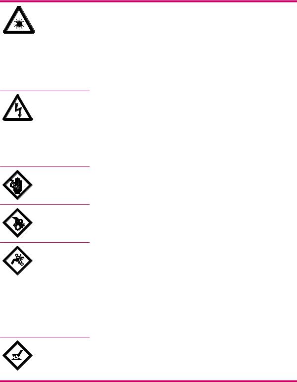
The following symbols appear on warning labels on the HP Indigo 7000 Digital Press:
Laser Hazard
DANGER. Invisible laser radiation may be present when doors are open and interlocks are defeated. Avoid direct exposure to beam.
Laser Radiation
The lasers in the press emit radiation in the invisible range. The laser unit in the writing head is enclosed in a protective housing and permits exit of the beam only at the writing head window (aperture) to the PIP. Do not insert or allow any reflective objects to be inserted in the path of the writing head window. Do not attempt to clean the writing head window or look into the writing head window while the unit is operational.
Electrical Hazard
HAZARDOUS VOLTAGE. Will cause severe or fatal injury. Apply Lockout procedure.
Electrical Hazards
Before you start any maintenance procedure that involves an electrically powered subsystem, make sure the subsystem is disconnected. If you are not sure that the subsystem is turned off, turn off the main power switch. Always follow the lockout procedure.
Live Current Hazard Alert
LIVE PARTS. Will cause severe or fatal injury. Apply Lockout procedure.
Entanglement Hazard Alert
WARNING. Open gears and mechanical parts. Can trap hands, fingers, clothing, and cause serious injury. Stay well clear.
Pinch Hazard Alert
WARNING. Pinch points between rollers, wheels, and other parts can trap hands, fingers, clothing, and cause serious injury. Stay well clear.
Mechanical Hazards
The press has a number of rotating parts and gripping devices (drums, gears, grippers, and so on). Exercise special care when performing any maintenance work around these parts. All repairs must be performed only by authorized customer engineers.
Do not climb into the substrate input or substrate exit for any reason. Doing so could be dangerous.
Hot Surface Hazard
WARNING. Hot surface. Can cause burns. Do not touch.
Heat Hazards
ENWW |
Warning signs and labels 11 |
The blanket and ITM drum become very hot during normal operation of the press, with temperatures up to 110°C (230°F). Do not touch the ITM drum or external heater with bare hands. Carelessness may cause burns. Wear thermal insulated gloves. Remove old blankets with needlenose pliers.
The following warnings also appear on the press:
CAUTION! |
To reduce the risk of electric shock, the main disconnect should be locked in the off position before |
|
servicing. |
|
|
DANGER. |
Invisible laser radiation may be present when open and interlock defeated. Avoid direct exposure to |
|
beam. |
|
|
WARNING: |
Hazardous moving parts. |
|
|
WARNING: |
Hazardous Voltage. Can cause damage. |
|
|
WARNING: |
Hot surface. Can cause burns. Do not touch. |
Emergency Stop Button
HIGH LEAKAGE CURRENT: Earth connection essential before connecting supply
MAIN EARTH CONNECTION LOCATED ON MAIN CHASSIS.
Warning signs
Post warning signs that clearly emphasize the dangers involved in operating and maintaining the press. The following warnings are recommended:
●This press is to be operated by properly trained and qualified operators only.
●Do not wear ties, other loose clothing, or loose jewelry when operating and maintaining the unit.
●Flammable vapors from heated imaging oil may be present!
●No smoking, open flame, or sources of ignition allowed!
●Make sure that the room is properly ventilated at all times. See the HP Indigo 7000 Digital Press Site Preparation Guide.
●Danger of pinching and crushing from moving press parts!
●Keep hands away from moving press parts.
●Access to Main Power switch must remain free at all times.
●Do not operate the press with doors open.
●Ink and imaging oil are irritating to eyes and skin. Use rubber gloves.
●ITM drum and blanket are hot.
●External heating lamps are hot.
●Read and understand the material safety data sheets (MSDS) for consumables used with the press.
12 Chapter 3 Safety |
ENWW |
Placement of warning labels
Warning labels are placed in various locations on the press. Many of the warning labels on the press are behind doors or covers and on parts that may be accessible only to authorized service personnel.
ENWW |
Warning signs and labels 13 |
Safety devices
Material safety data sheets (MSDS)
MSDS are supplied for consumables, including the different HP ElectroInks, imaging oil and the imaging agent, adhesion promoters, and adhesion promoter test fluids. Keep the MSDS readily available in the work area. Read and consult them for your personal protection. Keep the MSDS in a protective plastic cover.
Fire extinguishing equipment
The HP Indigo 7000 Digital Press generates combustible fumes and is also internally heated, a danger of fire exists. Take the following precautions:
●Position fire extinguishers in visible locations within 7.6 m (25 ft) of the press and any flammable or combustible material storage areas.
●Require regular inspection of the fire extinguishers (at least annually) and have designated employees trained in their use. Employees should be retrained at least once a year.
Eye wash stations
The HP Indigo 7000 Digital Press uses inks and imaging oil that may be irritating to skin and eyes. In extreme cases of exposure, these may cause blindness. Take the following precautions:
●Install eye wash stations within 7.6 m (25 ft) of areas where the ink and imaging oil are handled, dispensed, or stored.
●Provide eye wash liquid at eye wash stations (available from most safety supply companies) that complies with ANSI standard Z358. 1–1990.
●Use safety glasses with side-shields and rubber gloves when handling ink and imaging oil (nitrile disposable gloves are recommended).
Noise levels
During printing, the operator is exposed to a maximum of 80 dBA of audio noise with all service doors and covers closed.
Heat insulating tools
The blanket, ITM drum, and external heating lamps become very hot during normal operation of the press, with temperatures up to 165°C (355°F). Touching these parts could cause burns. Take the following precautions when you work near the ITM drum or when you are replacing the blanket:
●Wait until the drum cools to below 60°C (140°F) before performing maintenance procedures.
●Do not place hands on the moving blanket. Use a tool to grip the blanket metal bar.
Electrical safety
The HP Indigo 7000 Digital Press must be properly grounded at all times. Before operating the unit, ensure that it is grounded in conformance with the electrical code standards for your country/region (see the HP Indigo 7000 Digital Press Site Preparation Guide for recommendations). If in doubt, check with a licensed electrician or with your customer care center.
14 Chapter 3 Safety |
ENWW |

WARNING! Do not operate the press if it is not properly grounded. Perform a weekly check of grounding cables.
If a cable has to be disconnected or reconnected during a maintenance procedure, you must electrically turn off and lockout the press. Turn off the press by using the main power switch.
ENWW |
Safety devices 15 |
Emergency power shutdown
The following can turn off all or some electrical power to the press:
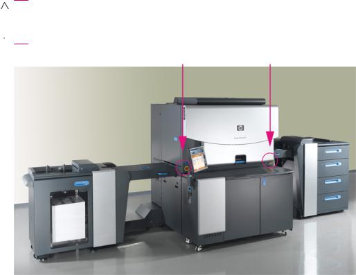
●Emergency Stop buttons: In an emergency, press one of the red Emergency Stop buttons to stop all mechanical movement in the main engine.
Red Emergency Stop buttons on a yellow background are located at both sides of the front door, and in other prominent locations on the press. When pressed, the button stops the press, and turns off electrical power to most system components.
◦To turn off power: press the button down.
◦To restore power: rotate the button clockwise to release.
CAUTION: Some press components continue to receive power after an Emergency Stop button is pressed.
 NOTE: Pressing an Emergency Stop button during printing can cause damage to the PIP and blanket.
Figure 3-1 Emergency Stop button on right and left sides of front door
16 Chapter 3 Safety |
ENWW |
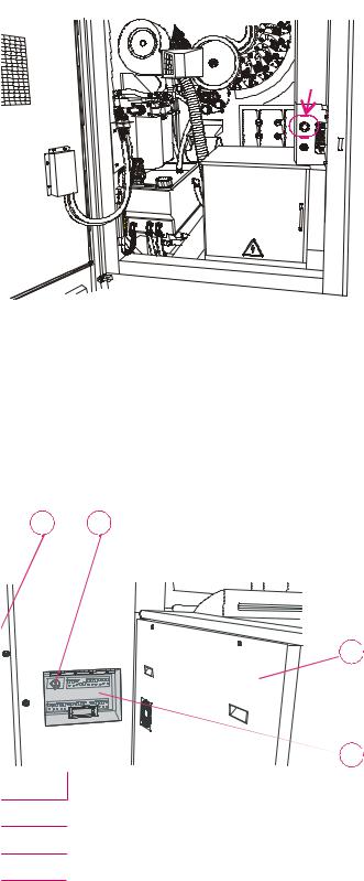
Figure 3-2 Emergency Stop button behind rear utility cabinet door
UTIL_CABINET-fig
Main supply disconnect switch: The main supply disconnect switch is permanently connected to the press via a conduit. A lockable disconnect device incorporated in the fixed wiring must be readily accessible. The device must be rated according to the specifications shown in the HP Indigo 7000 Digital Press Site Preparation Guide. This is an isolating device, which can be locked in the Off position to avoid an unexpected startup or release of electrical power during servicing or maintenance.
●Main power switch: The main power switch is located at the rear of the press. Access the main power switch through the opening near the rear door. Raise the switch cover. Rotate the main power switch to the left position to turn off all electrical power to the press engine.
Figure 3-3 Main power switch
1 |
2 |
PRE PIH _ |
-fgi |
0176A |
3 

4 

1Rear utility cabinet door
2Main power switch at exit side, behind stacker unit
3Stacker unit
4Switch cover
ENWW |
Emergency power shutdown 17 |
CAUTION: Always maintain free access to the main power switch, so that power can be immediately turned off in an emergency.
The main power switch does not disconnect power to the power distribution unit (PDU).
●Power Enable switch: The Power Enable switch is located on the upper left side of the press. The switch turns off power to the press engine subsystems, except for the computer and ink cabinet. To turn off power, put the Power Enable switch in the off position. To restore power, put the Power Enable switch in the on position.
Figure 3-4 Power Enable switch
18 Chapter 3 Safety |
ENWW |

Door interlocks and warning indicators
Door interlocks
The HP Indigo 7000 Digital Press has interlocked doors and covers that stop the press and turn off electrical power to system devices when these doors and covers are opened.
WARNING! Access to, and use of bypass keys is restricted to specifically trained and authorized personnel. Do not disconnect or override any of these safety devices.
The following doors and covers are interlocked:
Stacker |
Printing engine |
Feeder |
|
|
|
• Stacker top cover |
• Upper feed door |
• Feeder drawers |
|
|
|
• Stacker front door |
• Lower feed door |
• Feeder upper feed door |
|
|
|
|
• Ink cabinet door (disables air |
• Feeder to cover frame |
|
compressor to ink cans only) |
|
|
|
|
|
• Front door |
• Feeder vertical access door |
|
|
|
|
|
• Bridge |
|
|
|
|
Cleaning ECN door |
|
|
|
|
|
• External heater cover |
|
|
|
|
|
• Rear utility cabinet door |
|
|
|
|
If any of the doors or covers are opened, the interlock is activated and prevents operation of most devices, such as the high-voltage power supply and the main motor. Opening a feeder door will not turn off power to all parts of the feeder.
When you open an interlocked door :
●The press status changes to Off.
●The schematic illustration indicates that the door is open,
All opened interlocked doors and covers are indicated by• an open lock icon in the user interface.
ENWW |
Door interlocks and warning indicators 19 |
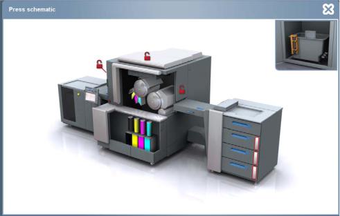
Figure 3-5 Press schematic showing open interlock doors
20 Chapter 3 Safety |
ENWW |

Attention lights
Attention lights are located on the input and exit sides of the printing engine.
Figure 3-6 Attention lights
Attention lights consist of three colors that indicate the following when lit:
●Green light:
◦Always on in Ready state
◦Flashing in Printing and Getting Ready states
●Yellow light:
◦Always on for all errors and for warning LEDs Warnings flagged:
◦An ink can is empty
◦Conductivity in one ink tank is high/low
◦Color adjustment is needed
◦Print cleaner is needed
◦Cooler drain is almost full
◦Stacker is 90% full
◦Only 10% of substrate is left in the feeder
●Red light:
◦Flashing when the bypass key is inserted, and a buzzer will sound before the press starts to rotate.
ENWW |
Attention lights 21 |
Loading...