


Maintenance and Service Guide
HP Elite Slice G2
© Copyright 2018 HP Development Company,
L.P.
Bluetooth is a trademark owned by its proprietor and used by HP Inc. under license. Intel is a trademark of Intel Corporation in the U.S. and other countries. Windows is either a registered trademark or trademark of Microsoft Corporation in the United States and/or other countries.
The information contained herein is subject to change without notice. The only warranties for HP products and services are set forth in the express warranty statements accompanying such products and services. Nothing herein should be construed as constituting an additional warranty. HP shall not be liable for technical or editorial errors or omissions contained herein.
First Edition: April 2018
Document Part Number: L14948-001
Product notice
This user guide describes features that are common to most models. Some features may not be available on your computer.
Not all features are available in all editions of Windows. This computer may require upgraded and/or separately purchased hardware, drivers and/or software to take full advantage of Windows functionality. Go to http://www.microsoft.com for details.
Software terms
By installing, copying, downloading, or otherwise using any software product preinstalled on this computer, you agree to be bound by the terms of the HP End User License Agreement (EULA). If you do not accept these license terms, your sole remedy is to return the entire unused product (hardware and software) within 14 days for a full refund subject to the refund policy of your seller.
For any further information or to request a full refund of the price of the computer, please contact your seller.

Safety warning notice
 WARNING! To reduce the possibility of heat-related injuries or of overheating the device, do not place
the device directly on your lap or obstruct the device air vents. Use the device only on a hard, flat surface. Do not allow another hard surface, such as an adjoining optional printer, or a soft surface, such as pillows or rugs or clothing, to block airflow. Also, do not allow the AC adapter to contact the skin or a soft surface, such as pillows or rugs or clothing, during operation. The device and the AC adapter comply with the user-accessible surface temperature limits de ned by the International Standard for Safety of Information Technology Equipment (IEC 60950-1).
iii
iv Safety warning notice

Table of contents
1 Product features ........................................................................................................................................... |
1 |
HP Elite Slice for Meeting Rooms G2 features ....................................................................................................... |
1 |
Top components .................................................................................................................................. |
2 |
Rear components ................................................................................................................................ |
2 |
Side components ................................................................................................................................. |
3 |
HP Video Ingest Module ......................................................................................................................................... |
3 |
HP Wireless Display Module (optional) .................................................................................................................. |
4 |
HP Optical Disc Drive (ODD) Module (optional) ...................................................................................................... |
5 |
HP Slice VESA plate (optional) ............................................................................................................................... |
5 |
Connecting or removing modules .......................................................................................................................... |
5 |
Connecting modules ............................................................................................................................ |
6 |
Connecting modules ......................................................................................................... |
6 |
Connecting the optional Slice VESA plate ......................................................................... |
6 |
Removing modules .............................................................................................................................. |
8 |
Connecting AC power ............................................................................................................................................. |
9 |
Regulatory information and serial number location .......................................................................................... |
10 |
2 Illustrated parts catalog .............................................................................................................................. |
11 |
Major components ............................................................................................................................................... |
11 |
Modules (whole units) ......................................................................................................................................... |
13 |
Memory modules and processors ....................................................................................................................... |
13 |
Adapters ............................................................................................................................................................... |
13 |
Solid-state drives (2.5-inch and M.2) .................................................................................................................. |
14 |
3 Routine care, SATA drive guidelines, and disassembly preparation .................................................................. |
15 |
Electrostatic discharge information .................................................................................................................... |
15 |
Generating static ............................................................................................................................... |
15 |
Preventing electrostatic damage to equipment ............................................................................... |
16 |
Personal grounding methods and equipment .................................................................................. |
16 |
Grounding the work area ................................................................................................................... |
16 |
Recommended materials and equipment ........................................................................................ |
17 |
Operating guidelines ........................................................................................................................................... |
17 |
Routine care ......................................................................................................................................................... |
18 |
General cleaning safety precautions ................................................................................................ |
18 |
Cleaning the computer case .............................................................................................................. |
18 |
Cleaning the keyboard ....................................................................................................................... |
18 |
v
Cleaning the monitor ......................................................................................................................... |
19 |
Cleaning the mouse ........................................................................................................................... |
19 |
Service considerations ......................................................................................................................................... |
19 |
Tools and software requirements ..................................................................................................... |
19 |
Screws ............................................................................................................................................... |
19 |
Lithium coin cell battery .................................................................................................................... |
20 |
4 Removal and replacement procedures – HP Elite Slice Base Module ................................................................. |
21 |
Access panel ......................................................................................................................................................... |
21 |
Memory ................................................................................................................................................................ |
22 |
Memory module speci cations ......................................................................................................... |
22 |
Populating memory module slots .................................................................................................... |
23 |
Installing system memory modules ................................................................................................. |
24 |
2.5-inch, solid-state drive (SSD) ......................................................................................................................... |
26 |
Speaker ................................................................................................................................................................ |
29 |
Base Module ......................................................................................................................................................... |
30 |
WLAN module ...................................................................................................................................................... |
32 |
RTC battery .......................................................................................................................................................... |
34 |
Ambient sensor .................................................................................................................................................... |
36 |
Fan sink ................................................................................................................................................................ |
37 |
M.2 PCIe solid state drive (SSD) ........................................................................................................................... |
38 |
Processor ............................................................................................................................................................. |
40 |
System board ....................................................................................................................................................... |
41 |
Removing the system board ............................................................................................................. |
41 |
Updating SMBIOS information .......................................................................................................... |
43 |
System ID setup page ........................................................................................................................ |
44 |
System board callouts, front ............................................................................................................. |
45 |
System board callouts, rear .............................................................................................................. |
46 |
5 Computer Setup (F10) Utility ........................................................................................................................ |
47 |
Computer Setup (F10) Utilities ............................................................................................................................ |
47 |
Using Computer Setup (F10) Utilities ................................................................................................ |
47 |
Computer Setup–Main ....................................................................................................................... |
49 |
Computer Setup—Security ............................................................................................................... |
51 |
Computer Setup—Advanced ............................................................................................................. |
53 |
Recovering the con guration settings ................................................................................................................ |
58 |
6 Troubleshooting without diagnostics ............................................................................................................ |
59 |
Safety and comfort .............................................................................................................................................. |
59 |
Before you call for technical support .................................................................................................................. |
59 |
vi
Helpful hints ........................................................................................................................................................ |
60 |
Solving general problems .................................................................................................................................... |
61 |
Solving power problems ...................................................................................................................................... |
64 |
Solving audio problems ....................................................................................................................................... |
64 |
Solving keyboard and mouse problems .............................................................................................................. |
66 |
Solving hardware installation problems ............................................................................................................. |
67 |
Solving Network Problems .................................................................................................................................. |
68 |
Solving memory problems .................................................................................................................................. |
70 |
Solving USB flash drive problems ........................................................................................................................ |
71 |
Solving Internet access problems ....................................................................................................................... |
72 |
Solving software problems .................................................................................................................................. |
73 |
7 POST error messages and diagnostic front panel LEDs and audible codes ......................................................... |
74 |
POST numeric codes and text messages ............................................................................................................. |
74 |
Interpreting system validation diagnostic front panel LEDs and audible codes ................................................ |
79 |
8 Password security and resetting CMOS .......................................................................................................... |
82 |
Resetting the password jumper .......................................................................................................................... |
82 |
Clearing and resetting the BIOS ........................................................................................................................... |
84 |
9 Using HP PC Hardware Diagnostics ................................................................................................................ |
86 |
Using HP PC Hardware Diagnostics Windows ..................................................................................................... |
86 |
Downloading HP PC Hardware Diagnostics Windows ....................................................................... |
86 |
Downloading the latest HP PC Hardware Diagnostics Windows version ....................... |
87 |
Downloading HP Hardware Diagnostics Windows by product name or number |
|
(select products only) ..................................................................................................... |
87 |
Installing HP PC Hardware Diagnostics Windows ............................................................................. |
87 |
Using HP PC Hardware Diagnostics UEFI ............................................................................................................. |
87 |
Starting HP PC Hardware Diagnostics UEFI ....................................................................................... |
88 |
Downloading HP PC Hardware Diagnostics UEFI to a USB flash drive .............................................. |
88 |
Downloading the latest HP PC Hardware Diagnostics UEFI version .............................. |
88 |
Downloading HP PC Hardware Diagnostics UEFI by product name or number |
|
(select products only) ..................................................................................................... |
88 |
Using Remote HP PC Hardware Diagnostics UEFI settings (select products only) ............................................. |
89 |
Downloading Remote HP PC Hardware Diagnostics UEFI ................................................................. |
89 |
Downloading the latest Remote HP PC Hardware Diagnostics UEFI version ................. |
89 |
Downloading Remote HP PC Hardware Diagnostics UEFI by product name or |
|
number ............................................................................................................................ |
89 |
Customizing Remote HP PC Hardware Diagnostics UEFI settings .................................................... |
89 |
vii
10 Backing up, restoring, and recovering ......................................................................................................... |
91 |
Using Windows tools ........................................................................................................................................... |
91 |
Creating HP Recovery media (select products only) ........................................................................................... |
91 |
Using HP Recovery Manager to create recovery media .................................................................... |
92 |
Before you begin ............................................................................................................. |
92 |
Creating the recovery media ........................................................................................... |
92 |
Using the HP Cloud Recovery Download Tool to create recovery media .......................................... |
93 |
Restoring and recovery ........................................................................................................................................ |
93 |
Restoring, resetting, and refreshing using Windows tools .............................................................. |
93 |
Restoring using HP Recovery Manager and the HP Recovery partition ........................................... |
93 |
Recovering using HP Recovery Manager ........................................................................................... |
93 |
Recovering using the HP Recovery partition (select products only) ................................................ |
94 |
Recovering using HP Recovery media ............................................................................................... |
94 |
Changing the computer boot order ................................................................................................... |
95 |
Removing the HP Recovery partition (select products only) ............................................................ |
95 |
Appendix A Power cord set requirements ......................................................................................................... |
96 |
General Requirements ......................................................................................................................................... |
96 |
Japanese Power Cord Requirements ................................................................................................................... |
96 |
Country-Speci c Requirements .......................................................................................................................... |
97 |
Appendix B Statement of memory volatility ..................................................................................................... |
98 |
Nonvolatile memory usage ............................................................................................................................... |
100 |
Questions and answers ..................................................................................................................................... |
102 |
Using HP Sure Start (select models only) .......................................................................................................... |
103 |
Appendix C peci c tions ............................................................................................................................. |
104 |
Index ........................................................................................................................................................... |
105 |
viii
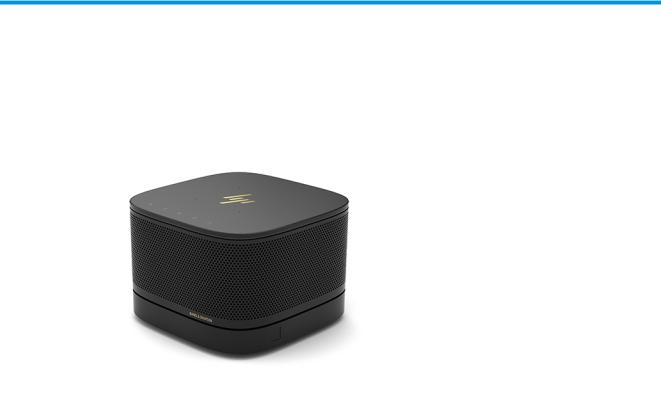
1Product features
HP Elite Slice for Meeting Rooms G2 features
The Elite Slice G2 features Bang & Olufsen audio and wireless communication for Intel Unite or Microsoft Skype Room System (SRS) conferencing software. Four speakers are on the Elite Slice G2, one in each corner and four microphones are on the top.
HP Elite Slice for Meeting Rooms G2 features |
1 |

Top components
The Elite Slice G2 top components enable call control with capacitive touch buttons for conference calls.
Item |
Component |
Item |
Component |
|
|
|
|
1 |
Answer/Call |
4 |
Volume up |
|
|
|
|
2 |
Mute |
5 |
Reject/Disconnect call |
|
|
|
|
3 |
Volume down |
|
|
|
|
|
|
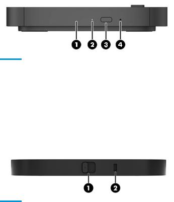
Rear components
Item |
Component |
Item |
Component |
|
|
|
|
1 |
Power button |
5 |
USB ports (2) |
|
|
|
|
2 |
Power jack |
6 |
Dual-Mode DisplayPort (D++) port |
|
|
|
|
3 |
RJ-45 (network) jack |
7 |
HDMI port |
|
|
|
|
4 |
USB type C port with Alt Mode |
8 |
Security cable slot |
|
|
|
|
2Chapter 1 Product features
Side components
Item |
Component |
Item |
Component |
|
|
|
|
1 |
USB Type-C port |
2 |
Audio-out (headphone)/Audio-in (microphone) combo |
|
(disabled from factory, enabled through system BIOS) |
|
jack |
|
|
|
|
|
|
|
|
HP Video Ingest Module
The Video Ingest Module is required for the Microsoft SRS. This module enables a video source to be connected to the SRS.
The Video Ingest Module does not support Intel Unite software.
Item |
Component |
Item |
Component |
|
|
|
|
1 |
Security cable slot |
2 |
HDMI-in port |
|
|
|
|
HP Video Ingest Module |
3 |

HP Wireless Display Module (optional)
The Elite Slice G2 may be ordered with the optional Wireless Display Module. The wireless receiver transceiver included with the module can be attached to a display. The Wireless Display Module can transmit a signal up to 10 meters to the transceiver in the room.
TIP: For the best performance, be sure the line of sight between the wireless receiver transceiver and the Wireless Display Module is optimal.
Item |
Component |
Item |
Component |
|
|
|
|
1 |
Sync button |
3 |
Security cable slot |
|
|
|
|
2 |
Sync LED |
|
|
|
|
|
|
Item |
Component |
Item |
Component |
|
|
|
|
1 |
HDMI port |
5 |
Mounting plate release button |
|
|
|
|
2 |
USB Type A power connector |
6 |
Security screw |
|
|
|
|
3 |
Sync LED |
7 |
Wireless receiver transceiver |
|
|
|
|
4 |
Sync button |
8 |
Wireless receiver transceiver VESA plate |
|
|
|
|
4Chapter 1 Product features
HP Optical Disc Drive (ODD) Module (optional)
The ODD Module (available as an after-market option) may be ordered to add optical drive functionality. Additional optical drive modules may be connected to an Elite Slice G2 con guration, depending upon the power supply and the total number of powered modules.
Item |
Component |
Item |
Component |
|
|
|
|
1 |
Optical drive disc tray |
3 |
Optical drive eject button |
|
|
|
|
2 |
Optical drive light |
4 |
Manual eject hole |
|
|
|
|
HP Slice VESA plate (optional)
The optional Slice VESA plate enables the Elite Slice G2 assembly to be mounted onto a table. The Elite Slide G2 should not be mounted to a wall or under a desk.
Item |
Component |
Item |
Component |
|
|
|
|
1 |
Quick release latch |
2 |
Security cable slot |
|
|
|
|
Connecting or removing modules
Additional modules may be connected to the Elite Slice G2. Modules should be attached to the Base Module in the following order, from top to bottom:
●Video Ingest Module (required for the Microsoft SRS only)
●Wireless Display Module (optional)
●ODD Module (optional)
●VESA plate (optional)
HP Optical Disc Drive (ODD) Module (optional) |
5 |

Connecting modules
Connecting modules
 CAUTION: Before connecting modules, turn o the Elite Slice G2 and disconnect it from any AC power source.
Modules cannot be “hot-plugged” or “hot-swapped.”
1.Remove/disengage the security cable, if one is attached.
2.Remove all removable media, such as USB flash drives.
3. Turn o the Elite Slice G2 properly through the operating system, and then turn o any external devices.
4.Disconnect the AC power cord from the Elite Slice G2 and disconnect any external devices.
5.If the VESA plate is connected, slide the quick release latch to the unlocked position and remove the VESA plate.
6.Align the module connection port on the underside of the Elite Slice G2 with the module expansion
connector on the new module and press the computer down rmly.
You should hear a quiet click when the modules lock together. The module locks into place and hides the release latch of the module above it.
Repeat until all modules have been connected.
Connecting the optional Slice VESA plate
If the VESA plate is connected, the Elite Slice G2 can be mounted onto a table.
 CAUTION: Before connecting the VESA plate, turn o the Elite Slice G2 and disconnect it from any AC power source.
1.Slide the quick release latch on the VESA plate to the unlocked position. Position the connected modules over the VESA plate.
The VESA plate does not have a module expansion connector. Be sure that the ports of the Elite Slice G2 and the quick release latch and security cable slot of the VESA plate are all on the same side.
6Chapter 1 Product features

2.Press the modules down onto the VESA plate.
3.Slide the quick release latch on the back of the VESA plate to the locked position to lock all modules together.
 CAUTION: There are four tabs in the VESA plate. When you position the Elite Slice G2 con guration correctly onto the VESA plate and slide the quick release latch to the locked position, the four tabs lock the VESA plate to the Elite Slice G2 assembly. If the VESA plate is not correctly oriented, the quick release latch cannot be moved to the locked position and the modules are not secured.
4.Install a security cable in the VESA plate security cable slot to prevent the quick release latch from being unlocked and the modules from being separated.
 NOTE: The security cable is designed to act as a deterrent, but it may not prevent the computer from being mishandled or stolen.
Connecting or removing modules |
7 |

Removing modules
 CAUTION: Before disconnecting modules, turn o the Elite Slice G2 and disconnect it from any AC power source.
Modules cannot be “hot-plugged” or “hot-swapped.”
Modules must be removed one at a time, starting at the bottom. Removing the Base Module exposes the release latch of the module above it.
1.Remove/disengage the security cable, if one is attached.
2.Remove all removable media, such as USB flash drives.
3. Turn o the Elite Slice G2 properly through the operating system, and then turn o any external devices.
4.Disconnect the AC power cord from the Elite Slice G2 and disconnect any external devices.
5.If the VESA plate is connected, slide the quick release latch on the back of the VESA plate to the unlocked
position and lift the module stack o the VESA plate.
6.Beginning at the bottom, remove additional modules by pressing the release latch (1) on the underside of each module until it releases the module (2) above it.
8Chapter 1 Product features
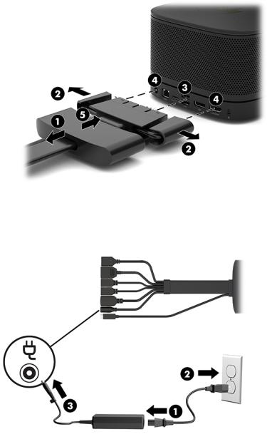
Connecting AC power
The Elite Slice G2 employs the HP Cable and Port Cover to supply power to the elements of the conferencing solution.
1.Connect the Cable and Port Cover to the Elite Slice G2:
a. Pull the port cover down (1) to expose the cable connectors.
b. |
Pull the rst and last connectors out (2) to each side. |
c. |
Beginning with the HDMI connector and nishing with the NIC connector, plug all middle connectors |
|
into the rear ports (3) on the Elite Slice G2. |
d.Connect side cables (4).
e.Push the port cover back over the cable connectors (5) to protect and secure the connectors.
2.Connect remaining equipment, such as a CoRC or a display, to the Cable and Port Cover.
3.Connect the AC power cord to the power adapter (1) and the other end to an AC outlet (2) .
4.Connect the power supply connector to the power connector on the Cable and Port Cover (3).
Connecting AC power |
9 |

Regulatory information and serial number location
Each computer has a unique serial number and a product ID number laser-etched on the base cover of the Elite Slice G2. A copy of these labels is inside the case. Keep these numbers available for use when contacting support for assistance.
Item |
Component |
Item |
Component |
|
|
|
|
1 |
Regulatory label |
3 |
Module connector |
|
|
|
|
2 |
Regulatory and service information |
|
|
|
|
|
|
10 Chapter 1 Product features

2Illustrated parts catalog
 NOTE: HP continually improves and changes product parts. For complete and current information on supported parts for your computer, go to http://partsurfer.hp.com, select your country or region, and then follow the on-screen instructions.
Major components
Item Description
(1)Fan sink
(2)Speaker
(3)WLAN module:
Intel® Dual Band Wireless-AC 7265 NV
Intel Dual Band Wireless-AC 8260 + Bluetooth 4.0
Intel Dual Band Wireless-AC 8260 + Bluetooth 4.0 (non-vPro)
Major components 11

Item Description
(4)HP Cable and Port Cover
(5)System board (includes replacement thermal material)
(6)Ambient sensor cable kit
xDisplay module dongle
xExternal power supply
x
x
x
65 W, nPFC
90 W, PFC
Power cord, C5
Mouse
USB, laser
USB, optical
USB, premium
USB, antimicrobial
Keyboards
USB slim
Wireless (keyboard + mouse)
Premium
USB, Smart card
xnot illustrated
Keyboard country codes
For use in country |
Spare part |
For use in country |
Spare part |
For use in country |
Spare part |
or region |
number |
or region |
number |
or region |
number |
|
|
|
|
|
|
Belgium |
-181 |
Internationally |
-L31 |
Russia |
-251 |
|
|
|
|
|
|
BHCSY |
-B41 |
Israel |
-BB1 |
Saudi Arabia |
-171, -DE1 |
|
|
|
|
|
|
Bulgaria |
-261 |
Italy |
-061 |
Spain |
-071 |
|
|
|
|
|
|
Canada (French) |
-121 |
Latin America |
-161 |
Switzerland |
-101, -111 |
|
|
|
|
|
|
Denmark |
-081 |
Norway |
-091 |
Taiwan |
-AB1 |
|
|
|
|
|
|
France |
-051 |
People’s Republic of China |
-AA1 |
Turkey |
-141 |
|
|
|
|
|
|
Germany |
-041 |
Portugal |
-131 |
United Kingdom |
-031 |
|
|
|
|
|
|
Greece |
-151 |
Romania |
-271 |
United States |
-001 |
|
|
|
|
|
|
Hungary |
-211 |
|
|
|
|
|
|
|
|
|
|
12 Chapter 2 Illustrated parts catalog

Modules (whole units)
Description
HP Slice G2 Base Module
HP Video Ingest Module
HP Wireless Display Module
Audio Module
Center of Room Module
Memory modules and processors
Description
Memory modules (DDR4-2400-MHz)
8-GB
4-GB
Intel Core processors
Intel Core i5-7500T, 2.7 GHz, 6-MB L2 cache, 35 W
Intel Core i5-7400T, 2.4 GHz, 6-MB L2 cache, 35 W
Intel Core i3-7100T, 3.4 GHz, 3-MB L2 cache, 35 W
Adapters
Description
DisplayPort to HDMI 1.4
DisplayPort to HDMI 2.0
DisplayPort to DVI
USB Type-C to VGA
USB Type-C to DisplayPort
USB Type-C to HDMI
USB Type-C to USB 3.0
USB -Type C to USB Type-A hub
Modules (whole units) 13

Solid-state drives (2.5-inch and M.2)
Description
Solid-state drive, M.2
256 GB, PCIe, NVMe, TLC
256 GB, PCIe, NVMe, value
Solid-state drive, 2.5-inch
256 GB, SATA-3, TLC
128 GB, SATA-3, TLC
14 Chapter 2 Illustrated parts catalog

3Routine care, SATA drive guidelines, and disassembly preparation
This chapter provides general service information for the computer. Adherence to the procedures and precautions described in this chapter is essential for proper service.
 CAUTION: When the computer is plugged into an AC power source, voltage is always applied to the system board. You must disconnect the power cord from the power source before opening the computer to prevent system board or component damage.
Electrostatic discharge information
A sudden discharge of static electricity from your nger or other conductor can destroy static-sensitive devices or microcircuitry. Often the spark is neither felt nor heard, but damage occurs. An electronic device exposed to electrostatic discharge (ESD) may not appear to be a ected at all and can work perfectly throughout a normal cycle. The device may function normally for a while, but it has been degraded in the internal layers, reducing its life expectancy.
Networks built into many integrated circuits provide some protection, but in many cases, the discharge contains enough power to alter device parameters or melt silicon junctions.
Generating static
The following table shows how humidity a ects the electrostatic voltage levels generated by di erent activities. A product can be degraded by 700 volts.
● Di erent activities generate di erent amounts of static electricity.
●Static electricity increases as humidity decreases.
|
Relative Humidity |
|
|
|
|
|
|
Event |
55% |
40% |
10% |
|
|
|
|
Walking across carpet |
7,500 V |
15,000 V |
35,000 V |
Walking across vinyl floor |
3,000 V |
5,000 V |
12,000 V |
Motions of bench worker |
400 V |
800 V |
6,000 V |
Removing DIPs from plastic tube |
400 V |
700 V |
2,000 V |
|
|
|
|
Removing DIPs from vinyl tray |
2,000 V |
4,000 V |
11,500 V |
Removing DIPs from Styrofoam |
3,500 V |
5,000 V |
14,500 V |
Removing bubble pack from PCB |
7,000 V |
20,000 V |
26,500 V |
Packing PCBs in foam-lined box |
5,000 V |
11,000 V |
21,000 V |
|
|
|
|
Electrostatic discharge information 15

Preventing electrostatic damage to equipment
Many electronic components are sensitive to ESD. Circuitry design and structure determine the degree of sensitivity. The following packaging and grounding precautions are necessary to prevent damage to electric components and accessories.
●To avoid hand contact, transport products in static-safe containers such as tubes, bags, or boxes.
●Protect all electrostatic-sensitive parts and assemblies with conductive or approved containers or packaging.
●Keep electrostatic-sensitive parts in their containers until they arrive at static-free stations.
●Place items on a grounded surface before removing them from their containers.
●Always be properly grounded when touching a sensitive component or assembly.
●Avoid contact with pins, leads, or circuitry.
●Place reusable electrostatic-sensitive parts from assemblies in protective packaging or conductive foam.
Personal grounding methods and equipment
Use the following equipment to prevent static electricity damage to equipment:
●Wrist straps are flexible straps with a maximum of one-megohm ± 10% resistance in the ground cords. To provide proper ground, a strap must be worn snugly against bare skin. The ground cord must be
connected to the banana plug connector on the grounding mat or workstation and t snugly into it.
●Heel straps/Toe straps/Boot straps can be used at standing workstations and are compatible with most types of shoes or boots. On conductive floors or dissipative floor mats, use them on both feet with a maximum of one-megohm ± 10% resistance between the operator and ground.
Static Shielding Protection Levels
Method |
Voltage |
|
|
Antistatic plastic |
1,500 |
Carbon-loaded plastic |
7,500 |
Metallized laminate |
15,000 |
|
|
Grounding the work area
To prevent static damage at the work area, observe the following precautions:
●Cover the work surface with approved static-dissipative material. Provide a wrist strap connected to the work surface and use properly grounded tools and equipment.
●Use static-dissipative mats, foot straps, or air ionizers to give added protection.
●Handle electrostatic-sensitive components, parts, and assemblies by the case or PCB laminate. Handle them only at static-free work areas.
●Turn o power and input signals before inserting and removing connectors or test equipment.
● Use xtures made of static-safe materials when xtures must directly contact dissipative surfaces.
●Keep work area free of nonconductive materials such as ordinary plastic assembly aids and Styrofoam.
● |
Use eld service tools, such as cutters, screwdrivers, and vacuums, that are conductive. |
16 Chapter 3 Routine care, SATA drive guidelines, and disassembly preparation
Recommended materials and equipment
The following grounding equipment is recommended to prevent electrostatic damage:
●Antistatic tape
●Antistatic smocks, aprons, or sleeve protectors
●Conductive bins and other assembly or soldering aids
●Conductive foam
●Conductive tabletop workstations with ground cords of one-megohm +/- 10% resistance
●Static-dissipative table or floor mats with hard ties to ground
●Field service kits
●Static awareness labels
●Wrist straps and footwear straps providing one-megohm +/- 10% resistance
●Material handling packages
●Conductive plastic bags
●Conductive plastic tubes
●Conductive tote boxes
●Opaque shielding bags
●Transparent metallized shielding bags
●Transparent shielding tubes
Operating guidelines
To prevent overheating and to help prolong the life of the computer:
●Keep the computer away from excessive moisture, direct sunlight, and extremes of heat and cold.
●Operate the computer on a sturdy, level surface. Leave a 10.2 cm (4-inch) clearance on all vented sides of the computer and above the monitor to permit the required airflow.
●Never restrict the airflow into the computer by blocking any vents or air intakes. Do not place the keyboard, with the keyboard feet down, directly against the front of the desktop unit as this also restricts airflow.
●Occasionally clean the air vents on all vented sides of the computer. Lint, dust, and other foreign matter can block the vents and limit the airflow. Be sure to unplug the computer before cleaning the air vents.
●Never operate the computer with the cover or side panel removed.
●Do not stack computers on top of each other or place computers so near each other that they are subject to each other’s re-circulated or preheated air.
●If the computer is to be operated within a separate enclosure, intake and exhaust ventilation must be provided on the enclosure, and the same operating guidelines listed above will still apply.
●Keep liquids away from the computer and keyboard.
Operating guidelines 17

●Never cover the ventilation slots on the monitor with any type of material.
●Install or enable power management functions of the operating system or other software, including sleep states.
Routine care
General cleaning safety precautions
1.Never use solvents or flammable solutions to clean the computer.
2.Never immerse any parts in water or cleaning solutions; apply any liquids to a clean cloth and then use the cloth on the component.
3.Always unplug the computer when cleaning with liquids or damp cloths.
4.Always unplug the computer before cleaning the keyboard, mouse, or air vents.
5.Disconnect the keyboard before cleaning it.
6.Wear safety glasses equipped with side shields when cleaning the keyboard.
Cleaning the computer case
Follow all safety precautions in General cleaning safety precautions on page 18 before cleaning the computer.
To clean the computer case, follow the procedures described below:
●To remove light stains or dirt, use plain water with a clean, lint-free cloth or swab.
●For stronger stains, use a mild dishwashing liquid diluted with water. Rinse well by wiping the surface with a cloth or swab dampened with clear water.
●For stubborn stains, use isopropyl (rubbing) alcohol. No rinsing is needed; alcohol will evaporate quickly without leaving a residue.
●After cleaning, always wipe the unit with a clean, lint-free cloth.
●Occasionally clean the air vents on the computer. Lint and other foreign matter can block the vents and limit the airflow.
Cleaning the keyboard
Follow all safety precautions in General cleaning safety precautions on page 18 before cleaning the keyboard.
To clean the tops of the keys or the keyboard body, follow the procedures described in Cleaning the computer case on page 18.
When cleaning debris from under the keys, review all rules in General cleaning safety precautions on page 18 before following these procedures:
 CAUTION: Use safety glasses equipped with side shields before attempting to clean debris from under the keys.
●Visible debris underneath or between the keys may be removed by vacuuming or shaking.
●Canned, pressurized air may be used to clean debris from under the keys. Caution should be used as too much air pressure can dislodge lubricants applied under the wide keys.
18 Chapter 3 Routine care, SATA drive guidelines, and disassembly preparation

●If you want to remove a key, use a specially designed key puller to prevent damage to the keys. This tool is available through many electronics supply outlets.
 CAUTION: Never remove a wide, level key (like the space bar) from the keyboard. If these keys are improperly removed or installed, the keyboard may not function properly.
●Cleaning under a key may be done with a swab moistened with isopropyl alcohol and then squeezed out. Be careful not to wipe away lubricants necessary for proper key functions. Use tweezers to remove any
bers or dirt in con ned areas. Allow the parts to air dry before reassembly.
Cleaning the monitor
●Wipe the monitor screen with a towelette designed for cleaning monitors or with a clean cloth moistened with water. Do not use sprays or aerosols directly on the screen; the liquid may seep into the housing and damage a component. Never use solvents or flammable liquids on the monitor.
●To clean the monitor body follow the procedures in Cleaning the computer case on page 18.
Cleaning the mouse
Before cleaning the mouse, ensure that the power to the computer is turned o .
● |
Clean the mouse ball by rst removing the retaining plate and the ball from the housing. Pull out any |
|
debris from the ball socket and wipe the ball with a clean, dry cloth before reassembly. |
●To clean the mouse body, follow the procedures in Cleaning the computer case on page 18.
Service considerations
Listed below are some of the considerations that you should keep in mind during the disassembly and assembly of the computer.
Tools and software requirements
To service the computer, you need the following:
●Torx T-15 screwdriver
●Flat-bladed screwdriver (may sometimes be used in place of the Torx screwdriver)
●Phillips #2 screwdriver
●Diagnostics software
Screws
The screws used in the computer are not interchangeable. They may have standard or metric threads and may be of di erent lengths. If an incorrect screw is used during the reassembly process, it can damage the unit. HP strongly recommends that all screws removed during disassembly be kept with the part that was removed, then returned to their proper locations.
 CAUTION: Metric screws have a black nish. U.S. screws have a silver nish and are used on hard drives only.
CAUTION: As each subassembly is removed from the computer, it should be placed away from the work area to prevent damage.
Service considerations |
19 |

Lithium coin cell battery
The battery that comes with the computer provides power to the real-time clock and has a minimum lifetime of about three years.
See the appropriate removal and replacement chapter for the chassis you are working on in this guide for instructions on the replacement procedures.
 WARNING! This computer contains a lithium battery. There is a risk of re and chemical burn if the battery is handled improperly. Do not disassemble, crush, puncture, short external contacts, dispose in water or re, or expose it to temperatures higher than 140ºF (60ºC). Do not attempt to recharge the battery.


 NOTE: Batteries, battery packs, and accumulators should not be disposed of together with general household waste. In order to forward them for recycling or proper disposal, please use the public collection system or return them to HP.
20 Chapter 3 Routine care, SATA drive guidelines, and disassembly preparation

4Removal and replacement procedures – HP Elite Slice Base Module
Adherence to the procedures and precautions described in this chapter is essential for proper service. After completing all necessary removal and replacement procedures, run the Diagnostics utility to verify that all components operate properly.
 NOTE: Not all features listed in this guide are available on all computers.


 NOTE: HP continually improves and changes product parts. For complete and current information on supported parts for your computer, go to http://partsurfer.hp.com, select your country or region, and then follow the on-screen instructions.
Access panel
The Elite Slice G2 access panel must be removed to access internal components (see Removing modules on page 8).
1.Remove the Elite Slice G2 from any additional modules.
2.Place the computer upside down on a flat surface covered with a soft cloth to protect the computer from scratches or other damage.
3. Loosen the four captive screws securing the access panel, and lift the panel o the computer.
To replace the access panel, reverse the removal procedures.
Access panel 21

Memory
Description
Memory modules (PC4-2400-MHz)
8-GB
4-GB
The memory module slots on the system board can be populated with up to two industry-standard memory modules. At least one small outline, dual inline memory module (SODIMM) is preinstalled. To achieve the maximum memory support, you can populate the system board with up to 32 GB (16 GB x 2) of memory.
 NOTE: Dual channel memory is recommended for Microsoft Skype Room Systems for better performance.
Memory module speci c tions
For proper system operation, the SODIMMs must adhere to the following speci cations
●industry-standard 288-pins
●unbu ered non-ECC PC4-17000 DDR4-2133 MHz-compliant
●1.2 volt DDR4-SDRAM SODIMMs
●Support CAS latency 15 DDR4 2400 MHz (15-15-15 timing)
●Contain the mandatory Joint Electronic Device Engineering Council (JEDEC) speci cation The computer supports the following:
●512-Mbit, 1-Gbit, and 2-Gbit non-ECC memory technologies
●Single-sided and double-sided SODIMMS
●SODIMMs constructed with x8 and x16 devices
 NOTE: To avoid compatibility issues, HP recommends that you use only HP memory modules in this computer. The system will not operate properly if you install unsupported DIMM memory. DIMMs constructed with x4 SDRAM are not supported.
22 Chapter 4 Removal and replacement procedures – HP Elite Slice Base Module
 Loading...