


 Loading...
LASERJET PRO CP1520
COLOR PRINTER SERIES
Service Manual

HP LaserJet Pro CP1520 Color Printer series
Service Manual
Copyright and License
© 2010 Copyright Hewlett-Packard
Development Company, L.P.
Reproduction, adaptation, or translation without prior written permission is prohibited, except as allowed under the copyright laws.
The information contained herein is subject to change without notice.
The only warranties for HP products and services are set forth in the express warranty statements accompanying such products and services. Nothing herein should be construed as constituting an additional warranty. HP shall not be liable for technical or editorial errors or omissions contained herein.
Part number: CE873-90934
Edition 1, 9/2010
Trademark Credits
Microsoft®, Windows®, Windows® XP, and Windows Vista® are U.S. registered trademarks of Microsoft Corporation.
ENERGY STAR and the ENERGY STAR mark are registered U.S. marks.

Conventions used in this guide
TIP: Tips provide helpful hints or shortcuts.
 NOTE: Notes provide important information to explain a concept or to complete a task.
 CAUTION: Cautions indicate procedures that you should follow to avoid losing data or damaging the product.
 WARNING! Warnings alert you to specific procedures that you should follow to avoid personal injury, catastrophic loss of data, or extensive damage to the product.
ENWW |
iii |
iv Conventions used in this guide |
ENWW |

Table of contents
1 Removal and replacement ............................................................................................................................. |
1 |
Introduction ........................................................................................................................................... |
2 |
Removal and replacement strategy ...................................................................................................... |
2 |
Electrostatic discharge ......................................................................................................................... |
3 |
Required tools ...................................................................................................................................... |
3 |
Service approach ................................................................................................................................. |
3 |
Before performing service .................................................................................................... |
3 |
After performing service ....................................................................................................... |
4 |
Post-service test .................................................................................................................. |
4 |
Print-quality test .................................................................................................. |
4 |
Parts removal order ............................................................................................................. |
4 |
Removal and replacement procedures ................................................................................................ |
5 |
Remove the print cartridges ................................................................................................. |
5 |
Rollers .................................................................................................................................. |
6 |
Pickup roller ........................................................................................................ |
6 |
Separation roller .................................................................................................. |
7 |
Transfer roller ...................................................................................................................... |
8 |
Feed assembly .................................................................................................................... |
9 |
External panels, covers, and doors ................................................................................... |
10 |
Right cover ........................................................................................................ |
10 |
Left cover .......................................................................................................... |
13 |
Front door and Tray 1 door ............................................................................... |
15 |
Control-panel module ........................................................................................ |
19 |
Rear-side cover ................................................................................................. |
21 |
Rear-upper cover .............................................................................................. |
22 |
Rear door and rear-lower cover ........................................................................ |
23 |
Top cover .......................................................................................................... |
25 |
Internal assemblies ............................................................................................................ |
27 |
Main motor ........................................................................................................ |
27 |
Fuser motor ....................................................................................................... |
29 |
Intermediate transfer belt (ITB) ......................................................................... |
30 |
Reinstall the ITB ............................................................................... |
35 |
DC controller PCA ............................................................................................. |
37 |
Special consideration ....................................................................... |
37 |
ENWW |
v |
Remove the DC controller PCA ........................................................ |
37 |
Formatter PCA .................................................................................................. |
40 |
Special consideration ....................................................................... |
40 |
Remove the formatter PCA .............................................................. |
40 |
Wireless PCA .................................................................................................... |
42 |
Power supply (high-voltage) .............................................................................. |
43 |
Power supply (low-voltage) ............................................................................... |
47 |
Power supply (fuser) ......................................................................................... |
53 |
Fuser ................................................................................................................. |
56 |
2 Solve problems ............................................................................................................................................. |
59 |
Solve problems checklist .................................................................................................................... |
60 |
Menu map .......................................................................................................................................... |
61 |
Troubleshooting process .................................................................................................................... |
62 |
Pre-troubleshooting checklist ............................................................................................. |
62 |
Power-on checks ............................................................................................................... |
64 |
Tools for troubleshooting .................................................................................................................... |
65 |
Diagrams ........................................................................................................................... |
65 |
Plug/jack locations ............................................................................................ |
65 |
Locations of major components ........................................................................ |
66 |
General timing charts ........................................................................................ |
68 |
General circuit diagram ..................................................................................... |
69 |
Use HP ToolboxFX ............................................................................................................ |
70 |
View the HP Color LaserJet CP1520 Series Toolbox ....................................... |
70 |
HP ToolboxFX sections ..................................................................................... |
71 |
Status ............................................................................................... |
71 |
Event log ........................................................................................... |
71 |
Help .................................................................................................. |
71 |
System Settings ................................................................................ |
71 |
Print Settings .................................................................................... |
74 |
Network Settings .............................................................................. |
74 |
Shop for Supplies ............................................................................. |
74 |
Other Links ....................................................................................... |
75 |
Internal print-quality test pages .......................................................................................... |
75 |
Interpret the Print Quality Page ......................................................................... |
75 |
Clean the product .............................................................................................. |
76 |
Configuration page ............................................................................................ |
76 |
Print-quality troubleshooting tools ...................................................................................... |
77 |
Repetitive image defects ................................................................................... |
77 |
Calibrate the product to align the colors ............................................................ |
77 |
Control panel menus .......................................................................................................... |
78 |
Reports menu .................................................................................................... |
78 |
Quick Forms menu ............................................................................................ |
79 |
vi |
ENWW |
System Setup menu .......................................................................................... |
79 |
Service menu .................................................................................................... |
82 |
Network Setup menu ......................................................................................... |
83 |
Interpret control panel messages ...................................................................................... |
84 |
Control panel message types ............................................................................ |
84 |
Control panel messages ................................................................................... |
84 |
Paper feeds incorrectly or becomes jammed ..................................................................................... |
95 |
The product does not pick up paper .................................................................................. |
95 |
The product picks up multiple sheets of paper .................................................................. |
95 |
Prevent paper jams ............................................................................................................ |
95 |
Clear jams .......................................................................................................................... |
96 |
Jam locations .................................................................................................... |
96 |
Jam in Tray 1 .................................................................................................... |
97 |
Jam in Tray 2 .................................................................................................... |
99 |
Jam in the fuser area ...................................................................................... |
100 |
Jam in the output bin ....................................................................................... |
101 |
Solve image quality problems .......................................................................................................... |
102 |
Use the correct paper type setting in the printer driver .................................................... |
102 |
Change the paper type setting for Windows ................................................... |
102 |
Change the paper type setting for Mac ........................................................... |
102 |
Adjust color settings in the printer driver .......................................................................... |
103 |
Change the color theme for a print job ............................................................ |
103 |
Change the color options ................................................................................ |
103 |
Use paper that meets HP specifications .......................................................................... |
104 |
Print a cleaning page ....................................................................................................... |
105 |
Calibrate the product to align the colors .......................................................................... |
105 |
Check the print cartridges ................................................................................................ |
105 |
Print the Supplies Status page ........................................................................ |
106 |
Inspect the print cartridge for damage ............................................................ |
106 |
Repeating defects ........................................................................................... |
107 |
Use the printer driver that best meets your printing needs .............................................. |
107 |
Clean the product ............................................................................................................................. |
109 |
The product does not print or it prints slowly .................................................................................... |
110 |
The product does not print ............................................................................................... |
110 |
The product prints slowly ................................................................................................. |
110 |
Solve connectivity problems ............................................................................................................. |
111 |
Solve direct-connect problems ........................................................................................ |
111 |
Solve network problems .................................................................................................. |
111 |
Poor physical connection ................................................................................ |
111 |
The computer is using the incorrect IP address for the product ...................... |
111 |
The computer is unable to communicate with the product .............................. |
112 |
The product is using incorrect link and duplex settings for the network .......... |
112 |
New software programs might be causing compatibility problems ................. |
112 |
The computer or workstation might be set up incorrectly ................................ |
112 |
ENWW |
vii |
The product is disabled, or other network settings are incorrect ..................... |
112 |
Service mode functions .................................................................................................................... |
113 |
Service menu ................................................................................................................... |
113 |
Service menu settings ..................................................................................... |
113 |
Restore the factory-set defaults ...................................................................... |
113 |
Secondary service menu ................................................................................................. |
113 |
Open the secondary service menu ................................................................. |
113 |
Secondary service menu structure .................................................................. |
114 |
Engine resets ................................................................................................................... |
114 |
Engine test page ............................................................................................. |
114 |
Cold reset ........................................................................................................ |
115 |
NVRAM initialization ........................................................................................ |
115 |
Product updates ............................................................................................................................... |
115 |
3 Parts and diagrams ..................................................................................................................................... |
117 |
Order parts by authorized service providers .................................................................................... |
118 |
Order replacement parts .................................................................................................. |
118 |
Related documentation and software .............................................................................. |
118 |
Supplies part numbers ..................................................................................................... |
118 |
Whole-unit replacement part numbers ............................................................................. |
118 |
How to use the parts lists and diagrams .......................................................................................... |
120 |
Assembly locations ........................................................................................................................... |
121 |
Base product (no optional trays or accessories) .............................................................. |
121 |
Covers, panels, and doors ............................................................................................................... |
122 |
Internal assemblies .......................................................................................................................... |
124 |
Alphabetical parts list ....................................................................................................................... |
134 |
Numerical parts list ........................................................................................................................... |
137 |
Appendix A Service and support ................................................................................................................. |
141 |
Hewlett-Packard limited warranty statement .................................................................................... |
142 |
HP's Premium Protection Warranty: LaserJet print cartridge limited warranty statement ................ |
143 |
Data stored on the print cartridge ..................................................................................................... |
144 |
End User License Agreement .......................................................................................................... |
145 |
OpenSSL .......................................................................................................................................... |
147 |
Customer support ............................................................................................................................. |
148 |
Repack the product .......................................................................................................................... |
149 |
Appendix B Product specifications ............................................................................................................. |
151 |
Physical specifications ..................................................................................................................... |
152 |
Power consumption, electrical specifications, and acoustic emissions ............................................ |
152 |
Environmental specifications ............................................................................................................ |
152 |
viii |
ENWW |
Appendix C Regulatory information ............................................................................................................ |
153 |
FCC regulations ............................................................................................................................... |
154 |
Environmental product stewardship program ................................................................................... |
155 |
Protecting the environment .............................................................................................. |
155 |
Ozone production ............................................................................................................ |
155 |
Power consumption ......................................................................................................... |
155 |
Paper use ........................................................................................................................ |
155 |
Plastics ............................................................................................................................ |
155 |
HP LaserJet print supplies ............................................................................................... |
155 |
Return and recycling instructions ..................................................................................... |
156 |
United States and Puerto Rico ........................................................................ |
156 |
Multiple returns (more than one cartridge) ..................................... |
156 |
Single returns ................................................................................. |
156 |
Shipping .......................................................................................... |
156 |
Non-U.S. returns ............................................................................................. |
156 |
Paper ............................................................................................................................... |
157 |
Material restrictions .......................................................................................................... |
157 |
Disposal of waste equipment by users in private households in the European Union .... |
157 |
Chemical substances ....................................................................................................... |
157 |
Material Safety Data Sheet (MSDS) ................................................................................ |
157 |
For more information ....................................................................................................... |
158 |
Declaration of conformity .................................................................................................................. |
159 |
Declaration of Conformity (wireless models) .................................................................................... |
161 |
Safety statements ............................................................................................................................. |
163 |
Laser safety ..................................................................................................................... |
163 |
Canadian DOC regulations .............................................................................................. |
163 |
VCCI statement (Japan) .................................................................................................. |
163 |
Power cord instructions ................................................................................................... |
163 |
Power cord statement (Japan) ......................................................................................... |
163 |
EMC statement (Korea) ................................................................................................... |
163 |
Laser statement for Finland ............................................................................................. |
164 |
GS statement (Germany) ................................................................................................. |
164 |
Substances Table (China) ............................................................................................... |
165 |
Restriction on Hazardous Substances statement (Turkey) ............................................. |
165 |
Additional statements for wireless products ..................................................................................... |
166 |
FCC compliance statement—United States .................................................................... |
166 |
Australia statement .......................................................................................................... |
166 |
Brazil ANATEL statement ................................................................................................ |
166 |
Canadian statements ....................................................................................................... |
166 |
European Union regulatory notice ................................................................................... |
166 |
Notice for use in France ................................................................................................... |
167 |
Notice for use in Russia ................................................................................................... |
167 |
Korean statement ............................................................................................................ |
167 |
Taiwan statement ............................................................................................................ |
167 |
ENWW |
ix |
Index ................................................................................................................................................................. |
169 |
x |
ENWW |

List of tables
Table 2-1 |
Major components ............................................................................................................................ |
66 |
Table 2-2 Repetitive image defects .................................................................................................................. |
77 |
|
Table 2-3 Secondary Service menu ............................................................................................................... |
114 |
|
Table 3-1 Order parts, accessories, and supplies .......................................................................................... |
118 |
|
Table 3-2 Related documentation and software ............................................................................................ |
118 |
|
Table 3-3 Supplies part numbers ................................................................................................................... |
118 |
|
Table 3-4 Whole-unit replacement part numbers ........................................................................................... |
118 |
|
Table 3-5 |
Base product .................................................................................................................................. |
121 |
Table 3-6 Covers, panels, and doors ............................................................................................................. |
123 |
|
Table 3-7 |
Internal components (1 of 4) .......................................................................................................... |
125 |
Table 3-8 |
Internal components (2 of 4) .......................................................................................................... |
127 |
Table 3-9 |
Internal components (3 of 4) .......................................................................................................... |
129 |
Table 3-10 Internal components (4 of 4) ........................................................................................................ |
131 |
|
Table 3-11 |
PCA location ................................................................................................................................ |
133 |
Table 3-12 Alphabetical parts list ................................................................................................................... |
134 |
|
Table 3-13 Numerical parts list ....................................................................................................................... |
137 |
|
Table B-1 |
Physical specifications ................................................................................................................... |
152 |
Table B-2 |
Operating-environment specifications ........................................................................................... |
152 |
ENWW |
xi |
xii |
ENWW |

List of figures
Figure 1-1 Phillips and Pozidriv screwdriver comparison ................................................................................... |
3 |
Figure 1-2 Parts-removal order .......................................................................................................................... |
4 |
Figure 1-3 Remove the print cartridge ................................................................................................................ |
5 |
Figure 1-4 Remove the pickup roller .................................................................................................................. |
6 |
Figure 1-5 Remove the separation roller (1 of 2) ............................................................................................... |
7 |
Figure 1-6 Remove the separation roller (2 of 2) ............................................................................................... |
8 |
Figure 1-7 Remove the transfer roller (1 of 3) .................................................................................................... |
8 |
Figure 1-8 Remove the transfer roller (2 of 3) .................................................................................................... |
9 |
Figure 1-9 Remove the transfer roller (3 of 3) .................................................................................................... |
9 |
Figure 1-10 Remove the feed assembly (1 of 2) .............................................................................................. |
10 |
Figure 1-11 Remove the feed assembly (2 of 2) .............................................................................................. |
10 |
Figure 1-12 Remove the right cover (1 of 4) .................................................................................................... |
11 |
Figure 1-13 Remove the right cover (2 of 4) .................................................................................................... |
11 |
Figure 1-14 Remove the right cover (3 of 4) .................................................................................................... |
12 |
Figure 1-15 Remove the right cover (4 of 4) .................................................................................................... |
12 |
Figure 1-16 Remove the left cover (1 of 4) ....................................................................................................... |
13 |
Figure 1-17 Remove the left cover (2 of 4) ....................................................................................................... |
13 |
Figure 1-18 Remove the left cover (3 of 4) ....................................................................................................... |
14 |
Figure 1-19 Remove the left cover (4 of 4) ....................................................................................................... |
14 |
Figure 1-20 Remove the front door and Tray 1 door (1 of 7) ........................................................................... |
15 |
Figure 1-21 Remove the front door and Tray 1 door (2 of 7) ........................................................................... |
15 |
Figure 1-22 Remove the front door and Tray 1 door (3 of 7) ........................................................................... |
16 |
Figure 1-23 Remove the front door and Tray 1 door (4 of 7) ........................................................................... |
16 |
Figure 1-24 Remove the front door and Tray 1 door (5 of 7) ........................................................................... |
17 |
Figure 1-25 Remove the front door and Tray 1 door (6 of 7) ........................................................................... |
17 |
Figure 1-26 Remove the front door and Tray 1 door (7 of 7) ........................................................................... |
18 |
Figure 1-27 Remove the control-panel module (1 of 3) ................................................................................... |
19 |
Figure 1-28 Remove the control-panel module (2 of 3) ................................................................................... |
19 |
Figure 1-29 Remove the control-panel module (3 of 3) ................................................................................... |
20 |
Figure 1-30 Remove the rear-side cover (1 of 2) ............................................................................................. |
21 |
Figure 1-31 Remove the rear-side cover (2 of 2) ............................................................................................. |
21 |
Figure 1-32 Remove the rear-upper cover (1 of 2) ........................................................................................... |
22 |
Figure 1-33 Remove the rear-upper cover (2 of 2) ........................................................................................... |
22 |
Figure 1-34 Remove the rear door and rear-lower cover (1 of 4) .................................................................... |
23 |
ENWW |
xiii |
Figure 1-35 Remove the rear door and rear-lower cover (2 of 4) .................................................................... |
23 |
Figure 1-36 Remove the rear door and rear-lower cover (3 of 4) .................................................................... |
24 |
Figure 1-37 Remove the rear door and rear-lower cover (4 of 4) .................................................................... |
24 |
Figure 1-38 Remove the top cover (1 of 4) ...................................................................................................... |
25 |
Figure 1-39 Remove the top cover (2 of 4) ...................................................................................................... |
26 |
Figure 1-40 Remove the top cover (3 of 4) ...................................................................................................... |
26 |
Figure 1-41 Remove the top cover (4 of 4) ...................................................................................................... |
27 |
Figure 1-42 Remove the main motor (1 of 2) ................................................................................................... |
27 |
Figure 1-43 Remove the main motor (2 of 2) ................................................................................................... |
28 |
Figure 1-44 Remove the fuser motor (1 of 2) ................................................................................................... |
29 |
Figure 1-45 Remove the fuser motor (2 of 2) ................................................................................................... |
29 |
Figure 1-46 Remove the ITB (1 of 9) ................................................................................................................ |
30 |
Figure 1-47 Remove the ITB (2 of 9) ................................................................................................................ |
30 |
Figure 1-48 Remove the ITB (3 of 9) ................................................................................................................ |
31 |
Figure 1-49 Remove the ITB (4 of 9) ................................................................................................................ |
31 |
Figure 1-50 Remove the ITB (5 of 9) ................................................................................................................ |
32 |
Figure 1-51 Remove the ITB (6 of 9) ................................................................................................................ |
32 |
Figure 1-52 Remove the ITB (7 of 9) ................................................................................................................ |
33 |
Figure 1-53 Remove the ITB (8 of 9) ................................................................................................................ |
33 |
Figure 1-54 Remove the ITB (9 of 9) ................................................................................................................ |
34 |
Figure 1-55 Reinstall the ITB (1 of 2) ............................................................................................................... |
35 |
Figure 1-56 Reinstall the ITB (2 of 2) ............................................................................................................... |
36 |
Figure 1-57 Remove the DC controller PCA (1 of 3) ........................................................................................ |
38 |
Figure 1-58 Remove the DC controller PCA (2 of 3) ........................................................................................ |
38 |
Figure 1-59 Remove the DC controller PCA (3 of 3) ........................................................................................ |
39 |
Figure 1-60 Remove the formatter PCA (1 of 2) .............................................................................................. |
41 |
Figure 1-61 Remove the formatter PCA (2 of 2) .............................................................................................. |
41 |
Figure 1-62 Remove the wireless PCA ............................................................................................................ |
42 |
Figure 1-63 Remove the power supply (high-voltage; 1 of 6) .......................................................................... |
43 |
Figure 1-64 Remove the power supply (high-voltage; 2 of 6) .......................................................................... |
44 |
Figure 1-65 Remove the power supply (high-voltage; 3 of 6) .......................................................................... |
44 |
Figure 1-66 Remove the power supply (high-voltage; 4 of 6) .......................................................................... |
45 |
Figure 1-67 Remove the power supply (high-voltage; 5 of 6) .......................................................................... |
45 |
Figure 1-68 Remove the power supply (high-voltage; 6 of 6) .......................................................................... |
46 |
Figure 1-69 Reinstall the power supply (high voltage) ..................................................................................... |
46 |
Figure 1-70 Remove the power supply (low-voltage; 1 of 10) .......................................................................... |
47 |
Figure 1-71 Remove the power supply (low-voltage; 2 of 10) .......................................................................... |
48 |
Figure 1-72 Remove the power supply (low-voltage; 3 of 10) .......................................................................... |
48 |
Figure 1-73 Remove the power supply (low-voltage; 4 of 10) .......................................................................... |
49 |
Figure 1-74 Remove the power supply (low-voltage; 5 of 10) .......................................................................... |
49 |
Figure 1-75 Remove the power supply (low-voltage; 6 of 10) .......................................................................... |
50 |
Figure 1-76 Remove the power supply (low-voltage; 7 of 10) .......................................................................... |
50 |
Figure 1-77 Remove the power supply (low-voltage; 8 of 10) .......................................................................... |
51 |
Figure 1-78 Remove the power supply (low-voltage; 9 of 10) .......................................................................... |
51 |
xiv |
ENWW |
Figure 1-79 Remove the power supply (low-voltage; 10 of 10) |
........................................................................ 52 |
|
Figure 1-80 Remove the power supply (fuser; 1 of 5) ...................................................................................... |
53 |
|
Figure 1-81 Remove the power supply (fuser; 2 of 5) ...................................................................................... |
53 |
|
Figure 1-82 Remove the power supply (fuser; 3 of 5) ...................................................................................... |
54 |
|
Figure 1-83 Remove the power supply (fuser; 4 of 5) ...................................................................................... |
54 |
|
Figure 1-84 Remove the power supply (fuser; 5 of 5) ...................................................................................... |
55 |
|
Figure 1-85 Remove the fuser (1 of 4) ............................................................................................................. |
56 |
|
Figure 1-86 Remove the fuser (2 of 4) ............................................................................................................. |
57 |
|
Figure 1-87 Remove the fuser (3 of 4) ............................................................................................................. |
57 |
|
Figure 1-88 Remove the fuser (4 of 4) ............................................................................................................. |
58 |
|
Figure 2-1 |
Major components .......................................................................................................................... |
66 |
Figure 2-2 |
Timing diagram ............................................................................................................................... |
68 |
Figure 2-3 |
Circuit diagram ................................................................................................................................ |
69 |
Figure 3-1 Base product (no optional trays or accessories) ........................................................................... |
121 |
|
Figure 3-2 Covers, panels, and doors ............................................................................................................ |
122 |
|
Figure 3-3 Internal components (1 of 4) ......................................................................................................... |
124 |
|
Figure 3-4 Internal components (2 of 4) ......................................................................................................... |
126 |
|
Figure 3-5 Internal components (3 of 4) ......................................................................................................... |
128 |
|
Figure 3-6 Internal components (4 of 4) ......................................................................................................... |
130 |
|
Figure 3-7 |
PCA location ................................................................................................................................. |
132 |
ENWW |
xv |
xvi |
ENWW |

1 Removal and replacement
●Introduction
●Removal and replacement strategy
●Electrostatic discharge
●Required tools
●Service approach
●Removal and replacement procedures
ENWW |
1 |

Introduction
This chapter describes the removal and replacement of field-replaceable units (FRUs) only.
Replacing FRUs is generally the reverse of removal. Occasionally, notes and tips are included to provide directions for difficult or critical replacement procedures.
HP does not support repairing individual subassemblies or troubleshooting to the component level.
Note the length, diameter, color, type, and location of each screw. Be sure to return each screw to its original location during reassembly.
Incorrectly routed or loose wire harnesses can interfere with other internal components and can become damaged or broken. Frayed or pinched harness wires can be difficult to find. When replacing wire harnesses, always use the provided wire loops, lance points, or wire-harness guides and retainers.
Removal and replacement strategy
 WARNING! Turn the product off, wait 5 seconds, and then remove the power cord before attempting to service the product. If this warning is not followed, severe injury can result, in addition to damage to the product. The power must be on for certain functional checks during troubleshooting. However, disconnect the power supply during parts removal.
Never operate or service the product with the protective cover removed from the laser/scanner assembly. The reflected beam, although invisible, can damage your eyes.
The sheet-metal parts can have sharp edges. Be careful when handling sheet-metal parts.
 CAUTION: Do not bend or fold the flat flexible cables (FFCs) during removal or installation. Also, do not straighten pre-folds in the FFCs. You must fully seat all FFCs in their connectors. Failure to fully seat an FFC into a connector can cause a short circuit in a PCA.
 NOTE: To install a self-tapping screw, first turn it counterclockwise to align it with the existing thread pattern, and then carefully turn it clockwise to tighten. Do not overtighten. If a self-tapping screw-hole becomes stripped, repair the screw-hole or replace the affected assembly.
TIP: For clarity, some photos in this chapter show components removed that would not be removed to service the product. If necessary, remove the components listed at the beginning of a procedure before proceeding to service the product.
2 Chapter 1 Removal and replacement |
ENWW |
Electrostatic discharge
CAUTION: |
Some parts are sensitive to electrostatic discharge (ESD). Look for the ESD |
reminder when removing product parts. Always perform service work at an ESD-protected workstation or mat, or use an ESD strap. If an ESD workstation, mat, or strap is not available, ground yourself by touching the sheet-metal chassis before touching an ESD-sensitive part.
Protect the ESD-sensitive parts by placing them in ESD pouches when they are out of the product.
Required tools
●#2 Phillips screwdriver with a magnetic tip and a 152-mm (6-in) shaft length
●Small flat-blade screwdriver
●Needle-nose pliers
●ESD mat or ESD strap (if one is available)
●Penlight (optional)
 CAUTION: Always use a Phillips screwdriver (callout 1). Do not use a Pozidriv screwdriver (callout 2) or any motorized screwdriver. These can damage screws or screw threads.
Figure 1-1 Phillips and Pozidriv screwdriver comparison
Service approach
Before performing service
●Remove all paper from the product.
●Turn off the power using the power switch.
●Unplug the power cable and interface cable or cables.
●Place the product on an ESD workstation or mat, or use an ESD strap (if one is available). If an ESD workstation, mat, or strap is not available, ground yourself by touching the sheet-metal chassis before touching an ESD-sensitive part.
●Remove the print cartridge.
ENWW |
Electrostatic discharge 3 |
After performing service
●Plug in the power cable.
●Reinstall the print cartridge.
●Load paper in the product.
Post-service test
Perform the following test to verify that the repair or replacement was successful.
Print-quality test
1.Verify that you have completed the necessary reassembly steps.
2.Make sure that the tray contains clean, unmarked paper.
3.Attach the power cord and interface cable or interface cables, and then turn on the product.
4.Verify that the expected startup sounds occur.
5.Print a configuration page, and then verify that the expected printing sounds occur.
6.Print a demo page, and then verify that the print quality is as expected.
7.Send a print job from the host computer, and then verify that the output meets expectations.
8.Clean the outside of the product with a damp cloth.
Parts removal order
Use the following diagram to determine which parts must be removed before removing other parts.
Figure 1-2 Parts-removal order
Component |
Remove |
Remove |
Remove |
Remove |
Remove |
Remove |
Remove |
|||||||||
|
|
|
|
|
|
|
|
|
|
|
|
|
|
|
|
|
|
Print cartridges |
Cartridge drawer |
|
|
|
|
|
|
|
|
|
|
|
|
||
|
Pickup roller |
Tray 2 |
|
|
|
|
|
|
|
|
|
|
|
|
||
Separation roller |
Tray 2 |
|
|
|
|
|
|
|
|
|
|
|
|
|||
Transfer roller |
|
|
|
|
|
|
|
|
|
|
|
|
|
|
||
|
Feed assembly |
|
|
|
|
|
|
|
|
|
|
|
|
|
|
|
Right cover |
Tray 2 |
|
|
|
|
|
|
|
|
|
|
|
|
|||
Left cover |
Tray 2 |
|
|
|
|
|
|
|
|
|
|
|
|
|||
Front door and Tray 1 door |
|
|
|
|
|
|
|
|
|
|
|
|
|
|
||
Control-panel module |
Right cover |
|
|
|
|
|
|
|
|
|
|
|
|
|||
Rear-side cover |
Right cover |
|
|
|
|
|
|
|
|
|
|
|
|
|||
Rear-upper cover |
Right cover |
Left cover |
Rear-side cover |
|
|
|
|
|
|
|
|
|||||
Rear door and rear-lower cover |
Right cover |
Left cover |
Rear-side cover |
|
|
|
|
|
|
|
|
|||||
Top cover |
Right cover |
Left cover |
Control panel module |
Rear-side cover |
Rear-upper cover |
|
|
|
|
|||||||
|
Main motor |
Right cover |
|
|
|
|
|
|
|
|
|
|
|
|
||
|
Fuser motor |
Right cover |
|
|
|
|
|
|
|
|
|
|
|
|
||
|
Intermediate transfer belt |
Right cover |
Left cover |
Rear-side cover |
|
|
|
|
|
|
|
|
||||
|
DC controller PCA |
Right cover |
Left cover |
Control panel module |
Rear-side cover |
Rear-upper cover |
|
|
|
|
||||||
|
Formatter PCA |
Right cover |
|
|
|
|
|
|
|
|
|
|
|
|
||
|
Wireless PCA |
Right cover |
Control-panel module |
Rear-side cover |
Rear-upper cover |
Top cover |
|
|
|
|
||||||
|
Power supply (high-voltage) |
Right cover |
Left cover |
Control panel module |
Rear-side cover |
Rear-upper cover |
|
|
|
|
||||||
|
Power supply (low-voltage) |
Right cover |
Left cover |
Rear-side cover |
Rear door and |
|
|
|
|
|
|
|||||
|
|
|
|
|
|
|
|
|
rear-door lower cover |
|
|
|
|
|
|
|
|
Power supply (fuser) |
Right cover |
Left cover |
Rear-side cover |
Rear door and |
|
|
|
|
|
|
|||||
|
|
|
|
|
|
|
|
|
rear-door lower cover |
|
|
|
|
|
|
|
|
Fuser |
Right cover |
Left cover |
Control panel module |
Rear-side cover |
Rear-upper cover |
Rear door and |
Top cover |
||||||||
|
|
|
|
|
|
|
|
|
|
|
|
|
rear-door lower cover |
|
|
|
|
|
|
|
|
|
|
|
|
|
|
|
|
|
|
|
|
4 Chapter 1 Removal and replacement |
ENWW |

Removal and replacement procedures
Remove the print cartridges
 CAUTION: If toner gets on your clothing, wipe it off with a dry cloth and wash the clothing in cold water. Hot water sets toner into the fabric.
1.Open the front door and pull out the print-cartridge drawer.
2.Grasp the handle on the print cartridge, and then pull the cartridge straight up to remove it. Repeat this step for the remaining print cartridges.
 CAUTION: Do not touch the imaging drum on the bottom of the print cartridge. Finger prints on the imaging drum can cause print-quality problems.
Do not allow the image drum to contact any surface when the cartridges are set down. Protect the image drum at all times. Dust and debris can stick to the drum and cause print-quality problems.
Figure 1-3 Remove the print cartridge
3.Close the print-cartridge and front doors.
ENWW |
Removal and replacement procedures 5 |

Rollers
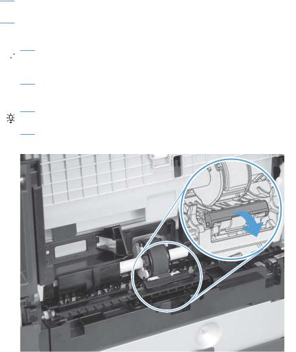
Pickup roller
 CAUTION: Do not touch the spongy roller surface unless you are going to replace the roller. Skin oils on the roller can cause paper pickup problems.
1.Use the following procedure to rotate the roller into the position required to remove it.
●Open the Secondary Service menu by pressing and holding both the Left arrow ( ) and the Cancel button simultaneously.
●Use the arrow buttons to select Pick roller, and then press the OK button.
●Press the OK button again to confirm that you want the pick roller to rotate.
●Turn the power off.
2.Remove Tray 2, and then carefully place the product front-side up.
 NOTE: Debris can scratch or damage the back of the product. Before you place the product front-side up, remove any debris from the work surface. If possible, set the product on a clean, dry cloth to prevent scratching and damage.
3.Release the two white plastic locking tabs and remove the pickup roller.
Figure 1-4 Remove the pickup roller
6 Chapter 1 Removal and replacement |
ENWW |
Separation roller
 CAUTION: Do not touch the spongy roller surface unless you are going to replace the roller. Skin oils on the roller can cause paper pickup problems.
1.Remove paper tray (if installed), and then carefully place the product front-side up.
 NOTE: Debris can scratch or damage the back of the product. Before you place the product front-side up, remove any debris from the work surface. If possible, set the product on a clean, dry cloth to prevent scratching and damage.
2.Carefully release the roller cover and rotate it down and away from the roller.
Reinstallation tip Make sure that this cover snaps into place over the roller when the roller and holder are reinstalled.
Figure 1-5 Remove the separation roller (1 of 2)
ENWW |
Removal and replacement procedures 7 |
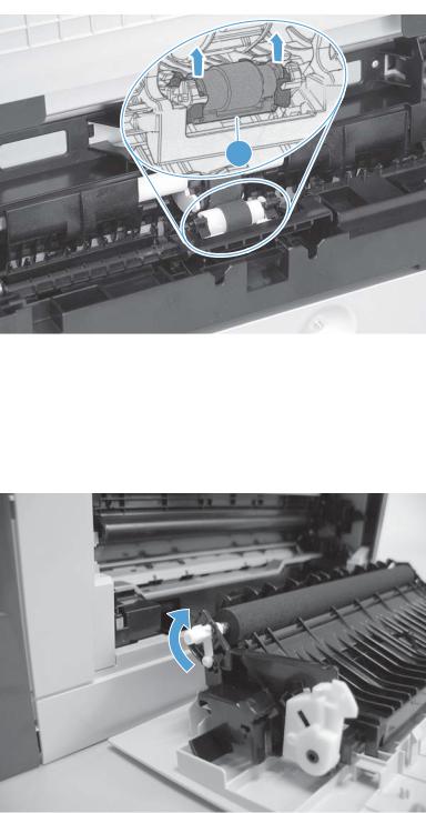
3.Use a small flat blade screwdriver to gently pry up on the roller and holder assembly (callout 1) to remove the roller and holder assembly.
Figure 1-6 Remove the separation roller (2 of 2)
1
Transfer roller
1.Open the rear door.
2.Release the retainer clip and then rotate it until the pin on the clip aligns with the slot in the mounting bracket.
Figure 1-7 Remove the transfer roller (1 of 3)
8 Chapter 1 Removal and replacement |
ENWW |

3.Remove the clip. Repeat these steps for the remaining retainer clip.
TIP: One of the clips is made from a black conductive plastic. Make sure that the clips are reinstalled on the side of the transfer roller that they are removed from.
Figure 1-8 Remove the transfer roller (2 of 3)
4.Slide the roller to one side to disengage the roller shaft from the mounting bracket, and then remove the transfer roller.
 CAUTION: Do not touch the black sponge portion of the roller. Skin oils can cause print-quality problems.
Figure 1-9 Remove the transfer roller (3 of 3)
Feed assembly
1.Open the rear door.
ENWW |
Removal and replacement procedures 9 |

2.Release one captive screw (callout 1) and release two tabs (callout 2).
Figure 1-10 Remove the feed assembly (1 of 2)
2
1
3.Remove the transfer roller assembly
Figure 1-11 Remove the feed assembly (2 of 2)
External panels, covers, and doors
Right cover
1.Remove Tray 2.
10 Chapter 1 Removal and replacement |
ENWW |
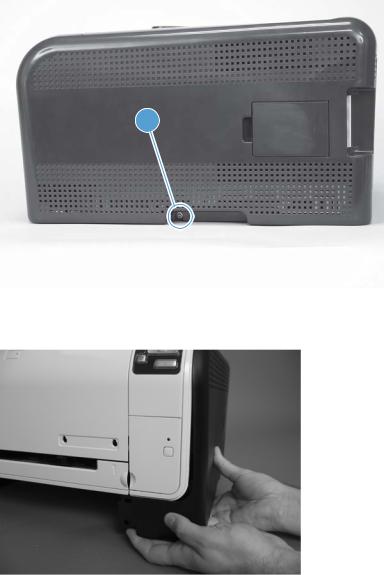
2.Remove one screw (callout 1).
Figure 1-12 Remove the right cover (1 of 4)
1
3.Carefully pry the front of the right cover away from the product to release one tab.
Figure 1-13 Remove the right cover (2 of 4)
ENWW |
Removal and replacement procedures 11 |
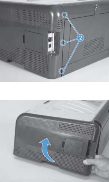
4.Use a small flatblade screwdriver to release three tabs (callout 2) at the back of the product.
Figure 1-14 Remove the right cover (3 of 4)
5.Rotate the bottom of the cover away from the product, and then slide it up to remove it.
Figure 1-15 Remove the right cover (4 of 4)
12 Chapter 1 Removal and replacement |
ENWW |
Loading...