


Maintenance and Service Guide
HP 260 G2 Desktop Mini PC
© Copyright 2016 HP Development Company, L.P. The information contained herein is subject to change without notice.
Intel, Core, Pentium, and Celeron are trademarks of Intel Corporation in the U.S. and other countries. Bluetooth is a trademark owned by its proprietor and used by HP under license. Microsoft and Windows are U.S. registered trademarks of the Microsoft group of companies. SD Logo is a trademark of its proprietor.
The following applies to HP systems with Intel Skylake or next-generation silicon chip-based system shipping with Windows 7, Windows 8, Windows 8.1 or Windows 10 Pro systems downgraded to Windows 7 Professional, Windows 8 Pro, or Windows 8.1: This version of Windows running with the processor or chipsets used in this system has limited support from Microsoft. For more information about Microsoft’s support, please see Microsoft’s Support Lifecycle FAQ at https://support.microsoft.com/lifecycle
The information contained herein is subject to change without notice. The only warranties for HP products and services are set forth in the express warranty statements accompanying such products and services. Nothing herein should be construed as constituting an additional warranty. HP shall not be liable for technical or editorial errors or omissions contained herein.
First Edition (April 2016)
Document Part Number: 860801-001
Product notice
This guide describes features that are common to most models. Some features may not be available on your computer.
Not all features are available in all editions of Windows 8. This computer may require upgraded and/or separately purchased hardware, drivers and/or software to take full advantage of Windows 8 functionality. See http://www.microsoft.com for details.
This computer may require upgraded and/or separately purchased hardware and/or a DVD drive to install the Windows 7 software and take full advantage of Windows 7 functionality. See http://windows.microsoft.com/en-us/ windows7/get-know-windows-7 for details.
Software terms
By installing, copying, downloading, or otherwise using any software product preinstalled on this computer, you agree to be bound by the terms of the HP End User License Agreement (EULA). If you do not accept these license terms, your sole remedy is to return the entire unused product (hardware and software) within 14 days for a refund subject to the refund policy of your place of purchase.
For any further information or to request a full refund of the computer, please contact your local point of sale (the seller).

Safety warning notice
 WARNING! To reduce the possibility of heat-related injuries or of overheating the device, do not place
the device directly on your lap or obstruct the device air vents. Use the device only on a hard, flat surface. Do not allow another hard surface, such as an adjoining optional printer, or a soft surface, such as pillows or rugs or clothing, to block airflow. Also, do not allow the AC adapter to contact the skin or a soft surface, such as pillows or rugs or clothing, during operation. The device and the AC adapter comply with the user-accessible surface temperature limits de ned by the International Standard for Safety of Information Technology Equipment (IEC 60950-1).
iii
iv Safety warning notice

Table of contents
1 Product features ........................................................................................................................................... |
1 |
Standard con guration features ........................................................................................................................... |
1 |
Serial number location .......................................................................................................................................... |
1 |
Front panel components ........................................................................................................................................ |
2 |
Rear panel components ......................................................................................................................................... |
2 |
2 Illustrated parts catalog ................................................................................................................................ |
3 |
Chassis spare parts ................................................................................................................................................ |
3 |
Computer major components ............................................................................................................. |
3 |
Miscellaneous parts ............................................................................................................................. |
4 |
Drives and memory ............................................................................................................................. |
5 |
3 Routine care, SATA drive guidelines, and disassembly preparation .................................................................... |
6 |
Electrostatic discharge information ...................................................................................................................... |
6 |
Generating static ................................................................................................................................. |
6 |
Preventing electrostatic damage to equipment ................................................................................. |
7 |
Personal grounding methods and equipment .................................................................................... |
7 |
Grounding the work area ..................................................................................................................... |
7 |
Recommended materials and equipment ........................................................................................... |
8 |
Operating guidelines .............................................................................................................................................. |
8 |
Routine care ........................................................................................................................................................... |
9 |
General cleaning safety precautions .................................................................................................. |
9 |
Cleaning the computer case ................................................................................................................ |
9 |
Cleaning the keyboard ......................................................................................................................... |
9 |
Cleaning the monitor ......................................................................................................................... |
10 |
Cleaning the mouse ........................................................................................................................... |
10 |
Service considerations ......................................................................................................................................... |
10 |
Tools and software requirements ..................................................................................................... |
10 |
Screws ............................................................................................................................................... |
10 |
Cables and connectors ...................................................................................................................... |
10 |
Hard Drives ........................................................................................................................................ |
11 |
Lithium coin cell battery .................................................................................................................... |
11 |
SATA hard drives .................................................................................................................................................. |
12 |
SATA hard drive cables ......................................................................................................................................... |
12 |
SATA data cable ................................................................................................................................. |
12 |
SMART ATA drives ................................................................................................................................................ |
12 |
v
Cable management .............................................................................................................................................. |
12 |
4 Removal and replacement procedures ........................................................................................................... |
13 |
Preparation for disassembly ............................................................................................................................... |
13 |
Access panel ......................................................................................................................................................... |
14 |
Hard drive ............................................................................................................................................................. |
15 |
Memory ................................................................................................................................................................ |
17 |
DDR4-SDRAM SODIMMs .................................................................................................................... |
17 |
Populating SODIMM sockets ............................................................................................................. |
18 |
Replacing SODIMMs ........................................................................................................................... |
19 |
WLAN module ...................................................................................................................................................... |
21 |
Speaker ................................................................................................................................................................ |
22 |
Fan ........................................................................................................................................................................ |
24 |
RTC battery .......................................................................................................................................................... |
25 |
Heat sink .............................................................................................................................................................. |
27 |
Drive cage and drive cable ................................................................................................................................... |
28 |
System board ....................................................................................................................................................... |
30 |
System board callouts ....................................................................................................................... |
33 |
Wireless antennas ................................................................................................................................................ |
34 |
Installing an optional rear port cover .................................................................................................................. |
38 |
5 Computer Setup (F10) Utility ........................................................................................................................ |
39 |
Computer Setup (F10) Utilities ............................................................................................................................ |
39 |
Using Computer Setup (F10) Utilities ................................................................................................ |
40 |
Computer Setup—File ....................................................................................................................... |
41 |
Computer Setup—Storage ................................................................................................................ |
42 |
Computer Setup—Security ............................................................................................................... |
43 |
Computer Setup—Power .................................................................................................................. |
45 |
Computer Setup—Advanced ............................................................................................................. |
45 |
Recovering the Con guration Settings ............................................................................................................... |
46 |
6 Troubleshooting without diagnostics ............................................................................................................ |
47 |
Safety and comfort .............................................................................................................................................. |
47 |
Before you call for technical support .................................................................................................................. |
47 |
Helpful hints ........................................................................................................................................................ |
48 |
Solving general problems .................................................................................................................................... |
49 |
Solving power problems ...................................................................................................................................... |
53 |
Solving hard drive problems ................................................................................................................................ |
54 |
Solving media card reader problems ................................................................................................................... |
56 |
Solving display problems .................................................................................................................................... |
57 |
vi
Solving audio problems ....................................................................................................................................... |
61 |
Solving printer problems ..................................................................................................................................... |
63 |
Solving keyboard and mouse problems .............................................................................................................. |
64 |
Solving Hardware Installation Problems ............................................................................................................. |
65 |
Solving Network Problems .................................................................................................................................. |
67 |
Solving memory problems .................................................................................................................................. |
70 |
Solving USB flash drive problems ........................................................................................................................ |
71 |
Solving front panel component problems .......................................................................................................... |
72 |
Solving Internet access problems ....................................................................................................................... |
72 |
Solving software problems .................................................................................................................................. |
74 |
7 POST error messages and diagnostic front panel LEDs and audible codes ......................................................... |
75 |
POST numeric codes and text messages ............................................................................................................. |
75 |
Interpreting system validation diagnostic front panel LEDs and audible codes ................................................ |
80 |
8 Password security and resetting CMOS .......................................................................................................... |
82 |
Resetting the password jumper .......................................................................................................................... |
82 |
Clearing and resetting the BIOS ........................................................................................................................... |
84 |
9 Using HP PC Hardware Diagnostics (UEFI) ....................................................................................................... |
86 |
Downloading HP PC Hardware Diagnostics (UEFI) to a USB device .................................................................... |
86 |
10 System backup and recovery ...................................................................................................................... |
88 |
Backing up, restoring, and recovering in Windows 10 ........................................................................................ |
88 |
Creating recovery media and backups .............................................................................................. |
88 |
Creating HP Recovery media (select products only) ...................................................... |
88 |
Using Windows tools ......................................................................................................................... |
89 |
Restore and recovery ........................................................................................................................ |
89 |
Recovering using HP Recovery Manager ........................................................................ |
90 |
What you need to know before you get started .......................................... |
90 |
Using the HP Recovery partition (select products only) .............................. |
91 |
Using HP Recovery media to recover ........................................................... |
91 |
Changing the computer boot order .............................................................. |
91 |
Removing the HP Recovery partition (select products only) ....................... |
91 |
Backing up, restoring, and recovering in Windows 7 .......................................................................................... |
92 |
Creating recovery media ................................................................................................................... |
92 |
Creating recovery media using HP Recovery Manager (select models only) ................. |
93 |
Creating recovery discs with HP Recovery Disc Creator (select models only) ............... |
94 |
Creating recovery discs ................................................................................ |
94 |
Backing up your information .......................................................................................... |
94 |
vii
System Restore ................................................................................................................................. |
95 |
System Recovery ............................................................................................................................... |
95 |
System Recovery when Windows is responding ............................................................ |
96 |
System Recovery when Windows is not responding ...................................................... |
96 |
System Recovery using recovery media (select models only) ....................................... |
97 |
Using HP Recovery Disc operating system discs (select models only) .......................... |
97 |
Appendix A Power Cord Set Requirements ........................................................................................................ |
99 |
General Requirements ......................................................................................................................................... |
99 |
Japanese Power Cord Requirements ................................................................................................................... |
99 |
Country-Speci c Requirements ........................................................................................................................ |
100 |
Appendix B Statement of Volatility ................................................................................................................ |
101 |
Appendix C peci c tions ............................................................................................................................. |
103 |
Index ........................................................................................................................................................... |
104 |
viii
1Product features
Standard con gur tion features
Features may vary depending on the model. For a complete listing of the hardware and software installed in the computer, run the diagnostic utility (included on some computer models only).
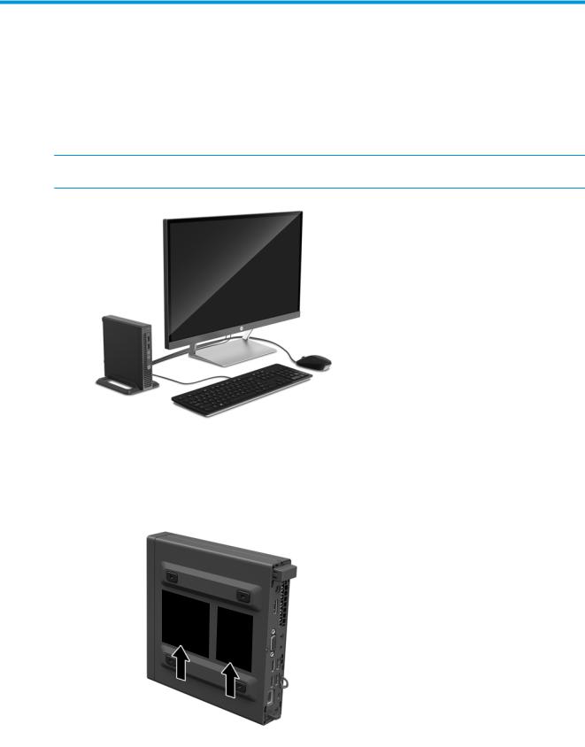
 NOTE: This computer model can be used in a tower orientation or a desktop orientation. The tower stand is sold separately.
Serial number location
Each computer has a unique serial number and a product ID number that are located on the exterior of the computer. Keep these numbers available for use when contacting customer service for assistance.
Standard con guration features |
1 |
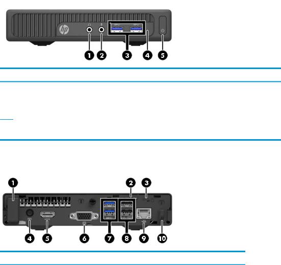
Front panel components
Drive con guration may vary by model.
Front panel components
1 |
Audio-out (headphone) jack |
4 |
Hard drive activity light |
|
|
|
|
2 |
Audio-in (microphone) jack |
5 |
Power button |
|
|
|
|
3 |
USB 3.0 ports |
|
|
NOTE: The Power On light is normally white when the power is on. If it is flashing red, there is a problem with the computer and it is displaying a diagnostic code. Refer to the Maintenance and Service Guide to interpret the code.
Rear panel components
Rear panel components
1 |
Optional antenna cover |
6 |
VGA monitor connector (black) |
|
|
|
|
2 |
Padlock loop |
7 |
USB 3.0 ports (blue) |
|
|
|
|
3 |
Security cable slot |
8 |
USB 2.0 ports (black) with keyboard |
|
|
|
wakeup function |
|
|
|
|
4 |
Power connector for the AC adapter |
9 |
RJ-45 (network) jack |
|
|
|
|
5 |
HDMI monitor connector |
10 |
Power supply cord retainer clip |
|
|
|
|
2Chapter 1 Product features
2Illustrated parts catalog
Chassis spare parts
 NOTE: HP continually improves and changes product parts. For complete and current information on supported parts for your computer, go to http://partsurfer.hp.com, select your country or region, and then follow the on-screen instructions.
Computer major components
Item Description
(1)Access panel
(2)Base enclosure
(3)System board with embedded processor (includes replacement thermal material) Intel Core i5-6200U processor
Intel Core i3-6100U processor Intel Pentium 4405U processor Intel Celeron 3855U processor
Chassis spare parts |
3 |
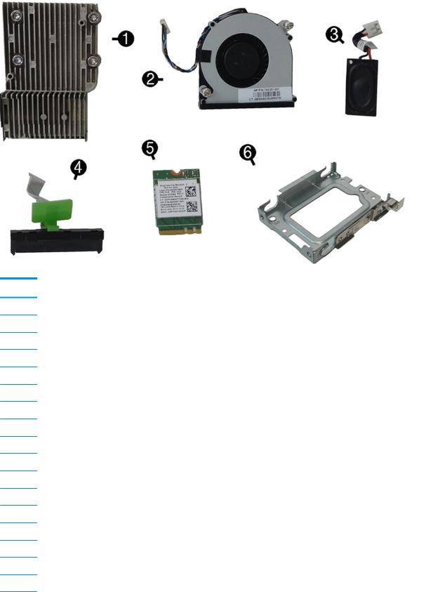
Miscellaneous parts
Item Description
(1)Heat sink
(2)Fan
(3)Speaker
(4)Hard drive connector and cable
(5)WLAN module (HP WLAN 802.11 b/g/n 1x1 + Bluetooth 4.0)
(6)Hard drive cage
Antennas and transceivers (not illustrated)
Power supply, 65W, 89% efficiency (not illustrated)
Stand (not illustrated)
HP Ultraslim Keyed Cable Lock (not illustrated)
Grommet, hard drive (not illustrated)
Adapter, USB to serial (not illustrated)
Mouse (not illustrated) HP USB
HP USB laser Unbranded USB
Keyboard (not illustrated)
4Chapter 2 Illustrated parts catalog
Item Description
HP USB slim
USB
HP USB Essential
HP wireless keyboard and mouse with dongle
Power cord, 1.83 m; (not illustrated)
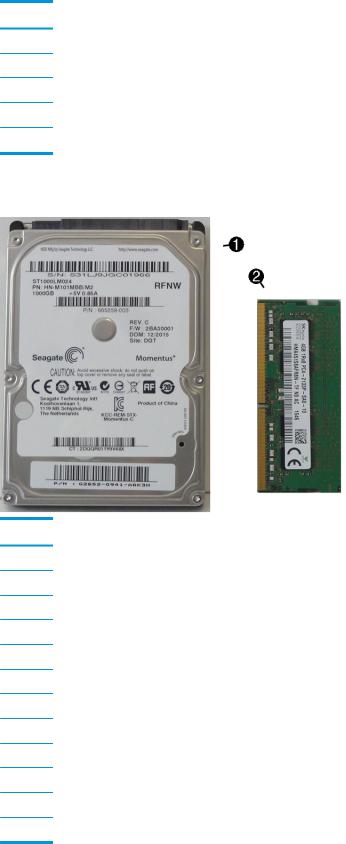
Drives and memory
Item Description
(1)Hard drive
1 TB, 5400 rpm hard drive, 2.5-inch
500 GB, 5400 rpm hard drive, 2.5-inch
Solid state drives (not illustrated) 256 GB
128 GB
Grommet, hard drive (not illustrated)
(2)Memory modules (SODIMM, PC4-17000) 16-GB
8-GB
4-GB
2-GB
Chassis spare parts |
5 |

3Routine care, SATA drive guidelines, and disassembly preparation
This chapter provides general service information for the computer. Adherence to the procedures and precautions described in this chapter is essential for proper service.
 CAUTION: When the computer is plugged into an AC power source, voltage is always applied to the system board. You must disconnect the power cord from the power source before opening the computer to prevent system board or component damage.
Electrostatic discharge information
A sudden discharge of static electricity from your nger or other conductor can destroy static-sensitive devices or microcircuitry. Often the spark is neither felt nor heard, but damage occurs. An electronic device exposed to electrostatic discharge (ESD) may not appear to be a ected at all and can work perfectly throughout a normal cycle. The device may function normally for a while, but it has been degraded in the internal layers, reducing its life expectancy.
Networks built into many integrated circuits provide some protection, but in many cases, the discharge contains enough power to alter device parameters or melt silicon junctions.
Generating static
The following table shows that:
● Di erent activities generate di erent amounts of static electricity.
●Static electricity increases as humidity decreases.
|
Relative Humidity |
|
|
|
|
|
|
Event |
55% |
40% |
10% |
|
|
|
|
Walking across carpet |
7,500 V |
15,000 V |
35,000 V |
Walking across vinyl floor |
3,000 V |
5,000 V |
12,000 V |
Motions of bench worker |
400 V |
800 V |
6,000 V |
Removing DIPs from plastic tube |
400 V |
700 V |
2,000 V |
|
|
|
|
Removing DIPs from vinyl tray |
2,000 V |
4,000 V |
11,500 V |
Removing DIPs from Styrofoam |
3,500 V |
5,000 V |
14,500 V |
Removing bubble pack from PCB |
7,000 V |
20,000 V |
26,500 V |
Packing PCBs in foam-lined box |
5,000 V |
11,000 V |
21,000 V |
These are then multi-packaged inside plastic tubes, trays, or Styrofoam.
 NOTE: 700 volts can degrade a product.
6Chapter 3 Routine care, SATA drive guidelines, and disassembly preparation

Preventing electrostatic damage to equipment
Many electronic components are sensitive to ESD. Circuitry design and structure determine the degree of sensitivity. The following packaging and grounding precautions are necessary to prevent damage to electric components and accessories.
●To avoid hand contact, transport products in static-safe containers such as tubes, bags, or boxes.
●Protect all electrostatic parts and assemblies with conductive or approved containers or packaging.
●Keep electrostatic sensitive parts in their containers until they arrive at static-free stations.
●Place items on a grounded surface before removing them from their container.
●Always be properly grounded when touching a sensitive component or assembly.
●Avoid contact with pins, leads, or circuitry.
●Place reusable electrostatic-sensitive parts from assemblies in protective packaging or conductive foam.
Personal grounding methods and equipment
Use the following equipment to prevent static electricity damage to equipment:
●Wrist straps are flexible straps with a maximum of one-megohm ± 10% resistance in the ground cords. To provide proper ground, a strap must be worn snug against bare skin. The ground cord must be
connected and t snugly into the banana plug connector on the grounding mat or workstation.
●Heel straps/Toe straps/Boot straps can be used at standing workstations and are compatible with most types of shoes or boots. On conductive floors or dissipative floor mats, use them on both feet with a maximum of one-megohm ± 10% resistance between the operator and ground.
Static Shielding Protection Levels
Method |
Voltage |
|
|
Antistatic plastic |
1,500 |
Carbon-loaded plastic |
7,500 |
Metallized laminate |
15,000 |
|
|
Grounding the work area
To prevent static damage at the work area, use the following precautions:
●Cover the work surface with approved static-dissipative material. Provide a wrist strap connected to the work surface and properly grounded tools and equipment.
●Use static-dissipative mats, foot straps, or air ionizers to give added protection.
●Handle electrostatic sensitive components, parts, and assemblies by the case or PCB laminate. Handle them only at static-free work areas.
●Turn o power and input signals before inserting and removing connectors or test equipment.
● Use xtures made of static-safe materials when xtures must directly contact dissipative surfaces.
●Keep work area free of nonconductive materials such as ordinary plastic assembly aids and Styrofoam.
● |
Use eld service tools, such as cutters, screwdrivers, and vacuums, that are conductive. |
Electrostatic discharge information |
7 |
Recommended materials and equipment
Materials and equipment that are recommended for use in preventing static electricity include:
●Antistatic tape
●Antistatic smocks, aprons, or sleeve protectors
●Conductive bins and other assembly or soldering aids
●Conductive foam
●Conductive tabletop workstations with ground cord of one-megohm +/- 10% resistance
●Static-dissipative table or floor mats with hard tie to ground
●Field service kits
●Static awareness labels
●Wrist straps and footwear straps providing one-megohm +/- 10% resistance
●Material handling packages
●Conductive plastic bags
●Conductive plastic tubes
●Conductive tote boxes
●Opaque shielding bags
●Transparent metallized shielding bags
●Transparent shielding tubes
Operating guidelines
To prevent overheating and to help prolong the life of the computer:
●Keep the computer away from excessive moisture, direct sunlight, and extremes of heat and cold.
●Operate the computer on a sturdy, level surface. Leave a 10.2-cm (4-inch) clearance on all vented sides of the computer and above the monitor to permit the required airflow.
●Never restrict the airflow into the computer by blocking any vents or air intakes. Do not place the keyboard, with the keyboard feet down, directly against the front of the desktop unit as this also restricts airflow.
●Occasionally clean the air vents on all vented sides of the computer. Lint, dust, and other foreign matter can block the vents and limit the airflow. Be sure to unplug the computer before cleaning the air vents.
●Never operate the computer with the cover or side panel removed.
●Do not stack computers on top of each other or place computers so near each other that they are subject to each other’s re-circulated or preheated air.
●If the computer is to be operated within a separate enclosure, intake and exhaust ventilation must be provided on the enclosure, and the same operating guidelines listed above will still apply.
●Keep liquids away from the computer and keyboard.
8Chapter 3 Routine care, SATA drive guidelines, and disassembly preparation

●Never cover the ventilation slots on the monitor with any type of material.
●Install or enable power management functions of the operating system or other software, including sleep states.
Routine care
General cleaning safety precautions
1.Never use solvents or flammable solutions to clean the computer.
2.Never immerse any parts in water or cleaning solutions; apply any liquids to a clean cloth and then use the cloth on the component.
3.Always unplug the computer when cleaning with liquids or damp cloths.
4.Always unplug the computer before cleaning the keyboard, mouse, or air vents.
5.Disconnect the keyboard before cleaning it.
6.Wear safety glasses equipped with side shields when cleaning the keyboard.
Cleaning the computer case
Follow all safety precautions in General cleaning safety precautions on page 9 before cleaning the computer.
To clean the computer case, follow the procedures described below:
●To remove light stains or dirt, use plain water with a clean, lint-free cloth or swab.
●For stronger stains, use a mild dishwashing liquid diluted with water. Rinse well by wiping it with a cloth or swab dampened with clear water.
●For stubborn stains, use isopropyl (rubbing) alcohol. No rinsing is needed as the alcohol will evaporate quickly and not leave a residue.
●After cleaning, always wipe the unit with a clean, lint-free cloth.
●Occasionally clean the air vents on the computer. Lint and other foreign matter can block the vents and limit the airflow.
Cleaning the keyboard
Follow all safety precautions in General cleaning safety precautions on page 9 before cleaning the keyboard.
To clean the tops of the keys or the keyboard body, follow the procedures described in Cleaning the computer case on page 9.
When cleaning debris from under the keys, review all rules in General cleaning safety precautions on page 9 before following these procedures:
 CAUTION: Use safety glasses equipped with side shields before attempting to clean debris from under the keys.
●Visible debris underneath or between the keys may be removed by vacuuming or shaking.
●Canned, pressurized air may be used to clean debris from under the keys. Caution should be used as too much air pressure can dislodge lubricants applied under the wide keys.
Routine care |
9 |

●If you remove a key, use a specially designed key puller to prevent damage to the keys. This tool is available through many electronic supply outlets.
 CAUTION: Never remove a wide leveled key (like the space bar) from the keyboard. If these keys are improperly removed or installed, the keyboard may not function properly.
●Cleaning under a key may be done with a swab moistened with isopropyl alcohol and squeezed out. Be careful not to wipe away lubricants necessary for proper key functions. Use tweezers to remove any
bers or dirt in con ned areas. Allow the parts to air dry before reassembly.
Cleaning the monitor
●Wipe the monitor screen with a clean cloth moistened with water or with a towelette designed for cleaning monitors. Do not use sprays or aerosols directly on the screen; the liquid may seep into the housing and damage a component. Never use solvents or flammable liquids on the monitor.
●To clean the monitor body follow the procedures in Cleaning the computer case on page 9.
Cleaning the mouse
Before cleaning the mouse, ensure that the power to the computer is turned o .
● |
Clean the mouse ball by rst removing the retaining plate and the ball from the housing. Pull out any |
|
debris from the ball socket and wipe the ball with a clean, dry cloth before reassembly. |
●To clean the mouse body, follow the procedures in Cleaning the computer case on page 9.
Service considerations
Listed below are some of the considerations that you should keep in mind during the disassembly and assembly of the computer.
Tools and software requirements
To service the computer, you need the following:
●Torx T-15 screwdriver
●Flat-bladed screwdriver (may sometimes be used in place of the Torx screwdriver)
●Diagnostics software
Screws
The screws used in the computer are not interchangeable. They may have standard or metric threads and may be of di erent lengths. If an incorrect screw is used during the reassembly process, it can damage the unit. HP strongly recommends that all screws removed during disassembly be kept with the part that was removed, then returned to their proper locations.
 CAUTION: As each subassembly is removed from the computer, it should be placed away from the work area to prevent damage.
Cables and connectors
Apply only the tension required to seat or unseat the cables during insertion or removal from the connector. Handle cables by the connector whenever possible. In all cases, avoid bending or twisting the cables, and ensure that the cables are routed in such a way that they cannot be caught or snagged by parts being removed or replaced.
10 Chapter 3 Routine care, SATA drive guidelines, and disassembly preparation

 CAUTION: When servicing this computer, ensure that cables are placed in their proper location during the reassembly process. Improper cable placement can damage the computer.
Hard Drives
Handle hard drives as delicate, precision components, avoiding all physical shock and vibration. This applies to failed drives as well as replacement spares.
●If a drive must be mailed, place the drive in a bubble-pack mailer or other suitable protective packaging and label the package “Fragile: Handle With Care.”
●Do not remove hard drives from the shipping package for storage. Keep hard drives in their protective packaging until they are actually mounted in the computer.
●Avoid dropping drives from any height onto any surface.
● |
If you are inserting or removing a hard drive, turn o the computer. Do not remove a hard drive while the |
|
computer is on or in standby mode. |
●Before handling a drive, ensure that you are discharged of static electricity. While handling a drive, avoid touching the connector.
●Do not use excessive force when inserting a drive.
● |
Avoid exposing a hard drive to liquids, temperature extremes, or products that have magnetic elds |
|
such as monitors or speakers. |
Lithium coin cell battery
The battery that comes with the computer provides power to the real-time clock and has a minimum lifetime of about three years.
See the appropriate removal and replacement chapter for the chassis you are working on in this guide for instructions on the replacement procedures.
 WARNING! This computer contains a lithium battery. There is a risk of re and chemical burn if the battery is handled improperly. Do not disassemble, crush, puncture, short external contacts, dispose in water or re, or expose it to temperatures higher than 140ºF (60ºC). Do not attempt to recharge the battery.


 NOTE: Batteries, battery packs, and accumulators should not be disposed of together with the general household waste. In order to forward them to recycling or proper disposal, please use the public collection system or return them to HP, their authorized partners, or their agents.
Service considerations |
11 |

SATA hard drives
Serial ATA Hard Drive Characteristics
Number of pins/conductors in data cable |
7/7 |
|
|
Number of pins in power cable |
15 |
|
|
Maximum data cable length |
39.37 in (100 cm) |
|
|
Data interface voltage di erential |
400-700 mV |
|
|
Drive voltages |
5 V |
|
|
Jumpers for con guring drive |
N/A |
|
|
Data transfer rate |
6.0 Gb/s |
|
|
SATA hard drive cables
SATA data cable
Always use an HP approved SATA 6.0 Gb/s cable as it is fully backwards compatible with the SATA 1.5 Gb/s drives.
Current HP desktop products ship with SATA 6.0 Gb/s hard drives.
SATA data cables are susceptible to damage if overflexed. Never crease a SATA data cable and never bend it tighter than a 30 mm (1.18 in) radius.
The SATA data cable is a thin, 7-pin cable designed to transmit data for only a single drive.
SMART ATA drives
The Self Monitoring Analysis and Recording Technology (SMART) ATA drives for the HP Personal Computers have built-in drive failure prediction that warns the user or network administrator of an impending failure or crash of the hard drive. The SMART drive tracks fault prediction and failure indication parameters such as reallocated sector count, spin retry count, and calibration retry count. If the drive determines that a failure is imminent, it generates a fault alert.
Cable management
Always follow good cable management practices when working inside the computer.
●Keep cables away from major heat sources like the heat sink.
●Keep cables clear of sliding or moveable parts to prevent them from being cut or crimped when the parts are moved.
●When folding a flat ribbon cable, never fold to a sharp crease. Sharp creases may damage the wires.
●Do not bend any cable sharply. A sharp bend can break the internal wires.
●Never bend a SATA data cable tighter than a 30 mm (1.18 in) radius.
●Never crease a SATA data cable.
12 Chapter 3 Routine care, SATA drive guidelines, and disassembly preparation
4Removal and replacement procedures
Adherence to the procedures and precautions described in this chapter is essential for proper service. After completing all necessary removal and replacement procedures, run the Diagnostics utility to verify that all components operate properly.
 NOTE: Not all features listed in this guide are available on all computers.


 NOTE: HP continually improves and changes product parts. For complete and current information on supported parts for your computer, go to http://partsurfer.hp.com, select your country or region, and then follow the on-screen instructions.
Preparation for disassembly
See Routine care, SATA drive guidelines, and disassembly preparation on page 6 for initial safety procedures.
1.Remove/disengage any security devices that prohibit opening the computer.
2.Remove all removable media, such as a USB flash drive, from the computer.
3. Turn o the computer properly through the operating system, then turn o any external devices.
 CAUTION: Turn o the computer before disconnecting any cables.
Regardless of the power-on state, voltage is always present on the system board as long as the system is plugged into an active AC outlet. In some systems the cooling fan is on even when the computer is in the “Standby,” or “Suspend” modes. The power cord should always be disconnected before servicing a unit.
4.Disconnect the power cord from the power outlet and disconnect any external devices.
5.If the computer is on a stand, remove the computer from the stand.
 WARNING! Beware of sharp edges inside the chassis.
Preparation for disassembly 13
Access panel
1.Prepare the computer for disassembly (Preparation for disassembly on page 13).
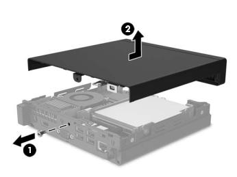
2. Remove the screw on the rear of the computer (1), and then slide the panel forward and lift if o the computer (2).
To install the access panel, reverse the removal procedure.
14 Chapter 4 Removal and replacement procedures
Hard drive
Description
Hard drives
1 TB, 5400 rpm hard drive, 2.5-inch
500 GB, 5400 rpm hard drive, 2.5-inch
Solid-state drives
256 GB
128 GB
Grommet, hard drive
 NOTE: Before you remove the old hard drive, be sure to back up the data from the old hard drive so that you can transfer the data to the new hard drive.
1.Prepare the computer for disassembly (Preparation for disassembly on page 13).
2.Remove the access panel Access panel on page 14.
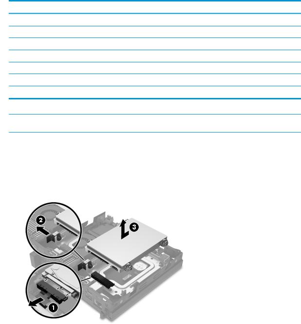
3.Unplug the combined power and data cable from the hard drive (1). Use the pull tab on the cable connector to unplug the cable. Then pull the release lever next to the rear of the hard drive outward (2). While pulling the release lever out, slide the drive back until it stops, and then lift the drive up and out of the bay (3).
Hard drive 15
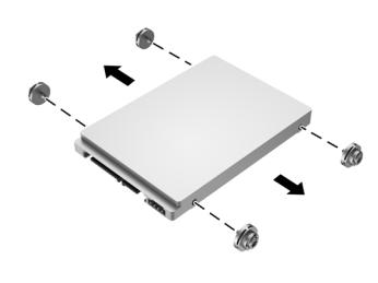
4.Remove the silver and blue isolation mounting guide screws from the sides of the old hard drive.
Reverse this procedure to replace the hard drive.
16 Chapter 4 Removal and replacement procedures

Memory
Description
16-GB, PC4-17000, SODIMM
8-GB, PC4-17000, SODIMM
4-GB, PC4-17000, SODIMM
2-GB, PC4-17000, SODIMM
The computer comes with at least one preinstalled double data rate 4 synchronous dynamic random access memory (DDR4-SDRAM) small outline dual inline memory module (SODIMM). There are two memory sockets on the system board that can be populated with up to 32 GB of memory.
DDR4-SDRAM SODIMMs
For proper system operation, the SODIMMs must be:
●industry-standard 288-pin
●unbu ered non-ECC PC4-17000 DDR4-2133 MT/s-compliant
●1.2 volt DDR4-SDRAM SODIMMs The SODIMMs must also:
●support CAS latency 15 DDR4 2133 MT/s (15-15-15 timing)
●contain the mandatory Joint Electronic Device Engineering Council (JEDEC) speci cation In addition, the computer supports:
●512-Mbit, 1-Gbit, 2-Gbit, 4-Gbit, and 8-Gbit non-ECC memory technologies
●single-sided and double-sided SODIMMs
 NOTE: The system will not operate properly if you install unsupported SODIMMs.
Memory 17
Populating SODIMM sockets
There are two SODIMM sockets on the system board, with one socket per channel. The sockets are labeled DIMM1 and DIMM3. The DIMM1 socket operates in memory channel B. The DIMM3 socket operates in memory channel A.
Item |
Description |
System Board Label |
Socket Color |
|
|
|
|
1 |
SODIMM1 socket, Channel B |
DIMM1 |
Black |
|
|
|
|
2 |
SODIMM2 socket, Channel A |
DIMM3 |
Black |
|
|
|
|
The system will automatically operate in single channel mode, dual channel mode, or flex mode, depending on how the SODIMMs are installed.
●The system will operate in single channel mode if the SODIMM sockets are populated in one channel only.
●The system will operate in a higher-performing dual channel mode if the memory capacity of the SODIMM in Channel A is equal to the memory capacity of the SODIMM in Channel B.
●The system will operate in flex mode if the memory capacity of the SODIMM in Channel A is not equal to the memory capacity of the SODIMM in Channel B. In flex mode, the channel populated with the least amount of memory describes the total amount of memory assigned to dual channel and the remainder is assigned to single channel. If one channel will have more memory than the other, the larger amount should be assigned to channel A.
●In any mode, the maximum operational speed is determined by the slowest SODIMM in the system.
18 Chapter 4 Removal and replacement procedures
Replacing SODIMMs
 CAUTION: You must disconnect the power cord and wait approximately 30 seconds for the power to drain before adding or removing memory modules. Regardless of the power-on state, voltage is always supplied to the memory modules as long as the computer is plugged into an active AC outlet. Adding or removing memory modules while voltage is present may cause irreparable damage to the memory modules or system board.
The memory module sockets have gold-plated metal contacts. When upgrading the memory, it is important to use memory modules with gold-plated metal contacts to prevent corrosion and/or oxidation resulting from having incompatible metals in contact with each other.
Static electricity can damage the electronic components of the computer or optional cards. Before beginning these procedures, ensure that you are discharged of static electricity by briefly touching a grounded metal object.
When handling a memory module, be careful not to touch any of the contacts. Doing so may damage the module.
1.Prepare the computer for disassembly (Preparation for disassembly on page 13).
2.Remove the access panel (Access panel on page 14).
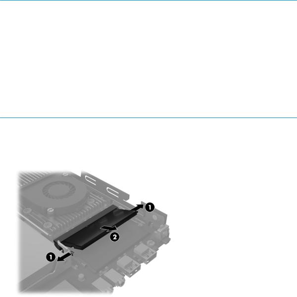
3.To remove a SODIMM, press outward on the two latches on each side of the SODIMM (1) then pull the SODIMM out of the socket (2).
Memory 19
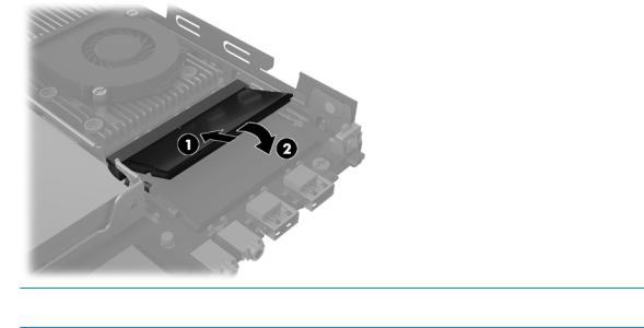
4.Slide the new SODIMM into the socket at approximately a 30° angle (1) then press the SODIMM down (2) so that the latches lock it in place.
 NOTE: A memory module can be installed in only one way. Match the notch on the module with the tab on the memory socket.
The computer automatically recognizes the additional memory when you turn on the computer.
20 Chapter 4 Removal and replacement procedures

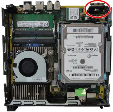
WLAN module
The WLAN module is located near from the front of the computer. The module is secured with one Phillips screw and has two connected antennas. The main antenna connects to a transceiver near the speaker assembly. The auxiliary antenna connects to a transceiver on the rear of the chassis.
 NOTE: WLAN module appearance may vary.
1.Prepare the computer for disassembly (Preparation for disassembly on page 13).
2.Remove the access panel (Access panel on page 14).
3.Disconnect the antenna cables from the module (1).
4.Remove the screw (2) that secures the module to the system board.
5.Pull the module away from the socket to remove (3).
To install the WLAN module, reverse the removal procedure.
 NOTE: WLAN modules are designed with a notch to prevent incorrect insertion.
WLAN module 21
Speaker
A single speaker is located behind the front bezel. It is secured by one plastic pin. A wireless antenna transceiver mounts to the front of the speaker assembly.
To remove the speaker:
1.Prepare the computer for disassembly (Preparation for disassembly on page 13).
2.Remove the access panel (Access panel on page 14).
3.Disconnect the speaker cable from the system board connector (1).
4.From the front of the computer, remove the pin that secures the speaker to the chassis (2).
22 Chapter 4 Removal and replacement procedures
 Loading...