


 Loading...
Maintenance and Service Guide
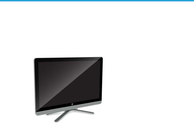
HP 205 G3 AiO Business PC
© Copyright 2016 HP Development Company, L.P. The information contained herein is subject to change without notice.
AMD is a trademark of Advanced Micro Devices, Inc. Bluetooth is a trademark owned by its proprietor and used by HP Inc. under license. Intel is a trademark of Intel Corporation in
the U.S. and other countries. Windows is either a registered trademark or trademark of Microsoft Corporation in the United States and/or other countries. Nvidia is a trademark and/or registered trademark of Nvidia Corporation in the U.S. and other countries.
The only warranties for HP products and services are set forth in the express warranty statements accompanying such products and services. Nothing herein should be construed as constituting an additional warranty. HP shall not be liable for technical or editorial errors or omissions contained herein.
First Edition: October 2016
Document Part Number: 912974-001
Software terms
By installing, copying, downloading, or otherwise using any software product preinstalled on this computer, you agree to be bound by the terms of the HP End User License Agreement (EULA). If you do not accept these license terms, your sole remedy is to return the entire unused product (hardware and software) within 14 days for a full refund subject to the refund policy of your seller.
Product notice
This user guide describes features that are common to most models. Some features may not be available on your computer.
Not all features are available in all editions of Windows. This computer may require upgraded and/or separately purchased hardware, drivers and/or software to take full advantage of Windows functionality. Go to http://www.microsoft.com for details.

About This Book
 WARNING! Text set o in this manner indicates that failure to follow directions could result in bodily harm or loss of life.
 CAUTION: Text set o in this manner indicates that failure to follow directions could result in damage to equipment or loss of information.
 NOTE: Text set o in this manner provides important supplemental information.
iii
iv About This Book

Table of contents
1 Product features ........................................................................................................................................... |
1 |
Standard con guration features ........................................................................................................................... |
1 |
Front panel components ........................................................................................................................................ |
2 |
Rear panel components ......................................................................................................................................... |
3 |
2 Illustrated parts catalog ................................................................................................................................ |
4 |
Computer major components ................................................................................................................................ |
4 |
Miscellaneous parts ............................................................................................................................................... |
5 |
3 Routine care, SATA drive guidelines, and disassembly preparation .................................................................... |
6 |
Electrostatic discharge information ...................................................................................................................... |
6 |
Generating static ................................................................................................................................. |
6 |
Preventing electrostatic damage to equipment ................................................................................. |
7 |
Personal grounding methods and equipment .................................................................................... |
7 |
Grounding the work area ..................................................................................................................... |
7 |
Recommended materials and equipment ........................................................................................... |
8 |
Operating guidelines .............................................................................................................................................. |
8 |
Routine care ........................................................................................................................................................... |
9 |
General cleaning safety precautions .................................................................................................. |
9 |
Cleaning the computer case ................................................................................................................ |
9 |
Cleaning the keyboard ......................................................................................................................... |
9 |
Cleaning the monitor ......................................................................................................................... |
10 |
Cleaning the mouse ........................................................................................................................... |
10 |
Service considerations ......................................................................................................................................... |
10 |
Tools and software requirements ..................................................................................................... |
10 |
Screws ............................................................................................................................................... |
10 |
Cables and connectors ...................................................................................................................... |
11 |
Hard Drives ........................................................................................................................................ |
11 |
Lithium coin cell battery .................................................................................................................... |
11 |
SATA hard drives .................................................................................................................................................. |
12 |
SMART ATA drives ................................................................................................................................................ |
12 |
4 Removal and replacement procedures ........................................................................................................... |
13 |
Preparation for disassembly ............................................................................................................................... |
13 |
Stand assembly ................................................................................................................................................... |
14 |
Rear cover ............................................................................................................................................................ |
15 |
v
Hard drive ............................................................................................................................................................. |
16 |
Memory module ................................................................................................................................................... |
17 |
Optical drive ......................................................................................................................................................... |
16 |
5 Computer Setup (F10) Utility ........................................................................................................................ |
19 |
Computer Setup (F10) Utilities ............................................................................................................................ |
19 |
Using Computer Setup (F10) Utilities ................................................................................................ |
19 |
Computer Setup–Main ....................................................................................................................... |
21 |
Computer Setup—Security ............................................................................................................... |
23 |
Computer Setup—Advanced ............................................................................................................. |
25 |
Recovering the Con guration Settings ............................................................................................................... |
30 |
6 Troubleshooting without diagnostics ............................................................................................................ |
31 |
Safety and comfort .............................................................................................................................................. |
31 |
Before you call for technical support .................................................................................................................. |
31 |
Helpful hints ........................................................................................................................................................ |
32 |
Solving general problems .................................................................................................................................... |
33 |
Solving power problems ...................................................................................................................................... |
37 |
Solving hard drive problems ................................................................................................................................ |
38 |
Solving media card reader problems ................................................................................................................... |
40 |
Solving display problems .................................................................................................................................... |
41 |
Solving audio problems ....................................................................................................................................... |
45 |
Solving printer problems ..................................................................................................................................... |
47 |
Solving keyboard and mouse problems .............................................................................................................. |
48 |
Solving hardware installation problems ............................................................................................................. |
50 |
Solving network problems .................................................................................................................................. |
51 |
Solving memory problems .................................................................................................................................. |
55 |
Solving USB flash drive problems ........................................................................................................................ |
56 |
Solving front panel component problems .......................................................................................................... |
57 |
Solving Internet access problems ....................................................................................................................... |
57 |
Solving software problems .................................................................................................................................. |
59 |
7 POST error messages and diagnostic front panel LEDs and audible codes ......................................................... |
60 |
POST numeric codes and text messages ............................................................................................................. |
60 |
Interpreting system validation diagnostic front panel LEDs and audible codes ................................................ |
65 |
8 Password security and resetting CMOS .......................................................................................................... |
67 |
Resetting CMOS and/or the password jumper .................................................................................................... |
68 |
Changing a Setup or Power-on password ........................................................................................................... |
69 |
Deleting a Setup or Power-on password ............................................................................................................. |
70 |
vi
9 Using HP PC Hardware Diagnostics (UEFI) ....................................................................................................... |
71 |
Downloading HP PC Hardware Diagnostics (UEFI) to a USB device .................................................................... |
71 |
10 System backup and recovery ...................................................................................................................... |
73 |
Backing up, restoring, and recovering in Windows 10 ........................................................................................ |
73 |
Creating recovery media and backups .............................................................................................. |
73 |
Creating HP Recovery media (select products only) ...................................................... |
73 |
Using Windows tools ......................................................................................................................... |
74 |
Restore and recovery ........................................................................................................................ |
74 |
Recovering using HP Recovery Manager ........................................................................ |
75 |
What you need to know before you get started .......................................... |
75 |
Using the HP Recovery partition (select products only) .............................. |
76 |
Using HP Recovery media to recover ........................................................... |
76 |
Changing the computer boot order .............................................................. |
76 |
Removing the HP Recovery partition (select products only) ....................... |
76 |
Backing up, restoring, and recovering in Windows 7 .......................................................................................... |
77 |
Creating recovery media ................................................................................................................... |
77 |
Creating recovery media using HP Recovery Manager (select models only) ................. |
78 |
Creating recovery discs with HP Recovery Disc Creator (select models only) ............... |
79 |
Creating recovery discs ................................................................................ |
79 |
Backing up your information .......................................................................................... |
79 |
System Restore ................................................................................................................................. |
80 |
System Recovery ............................................................................................................................... |
80 |
System Recovery when Windows is responding ............................................................ |
81 |
System Recovery when Windows is not responding ...................................................... |
81 |
System Recovery using recovery media (select models only) ....................................... |
82 |
Using HP Recovery Disc operating system discs (select models only) .......................... |
82 |
Appendix A Battery replacement ..................................................................................................................... |
84 |
Appendix B Statement of Volatility .................................................................................................................. |
87 |
Appendix C Power cord set requirements .......................................................................................................... |
88 |
General requirements .......................................................................................................................................... |
88 |
Japanese power cord requirements .................................................................................................................... |
88 |
Country-speci c requirements ............................................................................................................................ |
89 |
Appendix D peci c tions ............................................................................................................................... |
90 |
Index ............................................................................................................................................................. |
91 |
vii
viii
1Product features
Standard con gur tion features
Features may vary depending on the model. For support assistance and to learn more about the hardware and software installed on the computer model, run the HP Support Assistant utility.
Standard con guration features |
1 |

Front panel components
Item |
Description |
Item |
Description |
|
|
|
|
(1) |
Microphones (2) |
(4) |
SD Card slot |
|
|
|
|
(2) |
Camera light |
(5) |
Power button |
(3)Camera
2Chapter 1 Product features
Rear panel components
Item |
Description |
Item |
Description |
|
|
|
|
(1) |
Security lock slot |
(5) |
USB 3.0 ports (black) |
|
|
|
|
(2) |
USB 2.0 ports (2) (black) |
(6) |
HDMI port |
|
|
|
|
(3) |
RJ-45 network connector |
(7) |
Audio-out (headphone)/Audio-in (microphone) |
|
|
|
combo jack |
(4) Power cord connector
Rear panel components |
3 |

2Illustrated parts catalog
Computer major components
Description
Front bezel:
For use only on INX HD computer models
For use only on LG/AUO HD computer models
Non-TouchScreen display panel kit:
For use only on INX HD computer models
For use only on LG/AUO HD computer models
Backlight cable:
For use only on INX HD computer models
For use only on LG/AUO HD computer models
Low-voltage di erenti l signalling (LVDS) cable:
For use only on INX HD computer models
For use only on LG/AUO HD computer models
Webcam/microphone module (includes cable)
Speaker Kit (includes left and right speakers and cables)
System board (includes replacement thermal material)
Processor (AMD E2-7110 1.80-GHz, 1800-MHz FSB, 2.0-MB L2 cache, quad core, 12 to 15 W; includes replacement thermal material)
Card reader/power board
Card reader/power board cable
Memory modules (2, PC3-12800 [DDR3L-1600] SODIMM, 1.35 V):
8-GB
4-GB
2-GB
Fan
Heat sink (includes replacement thermal material)
Realtek 802.11b/g/n 1×1 Wi-Fi Combo Adapter
Hard drive:
2-TB, 7200-rpm, 8.9-cm (3.5-in)
1-TB, 7200-rpm, 8.9-cm (3.5-in)
500-GB, 7200-rpm, 8.9-cm (3.5-in)
4Chapter 2 Illustrated parts catalog

Description
Hard drive cable
DVD±RW Super-Multi drive
Optical drive bezel blank
Optical drive cable
Rear cover
Stand assembly
Miscellaneous parts
Description
Power cord with C5 receptacle, 1.00-meter (3.28-feet)
For use in Argentina
For use in the United States
Power supply, 65-W HP Smart AC adapter (non-PFC, non-slim)
Keyboard:
HP USB keyboard in black nish with United States layout, for use in Argentina
HP USB slim Windows 8 keyboard for use in the United States
Mouse:
HP USB optical mouse
USB mouse, Portia design
Miscellaneous parts |
5 |

3Routine care, SATA drive guidelines, and disassembly preparation
This chapter provides general service information for the computer. Adherence to the procedures and precautions described in this chapter is essential for proper service.
 CAUTION: When the computer is plugged into an AC power source, voltage is always applied to the system board. The power cord must be disconnected from the power source before opening the computer to prevent system board or component damage.
Electrostatic discharge information
A sudden discharge of static electricity from your nger or other conductor can destroy static-sensitive devices or microcircuitry. Often the spark is neither felt nor heard, but damage occurs. An electronic device exposed to electrostatic discharge (ESD) may not appear to be a ected at all and can work perfectly throughout a normal cycle. The device may function normally for a while, but it has been degraded in
the internal layers, reducing its life expectancy.
Networks built into many integrated circuits provide some protection, but in many cases, the discharge contains enough power to alter device parameters or melt silicon junctions.
Generating static
The following table shows how humidity a ects the electrostatic voltage levels generated by di erent activities. A product can be degraded by 700 volts.
● Di erent activities generate di erent amounts of static electricity.
●Static electricity increases as humidity decreases.
|
Relative Humidity |
|
|
|
|
|
|
Event |
55% |
40% |
10% |
|
|
|
|
Walking across carpet |
7,500 V |
15,000 V |
35,000 V |
Walking across vinyl floor |
3,000 V |
5,000 V |
12,000 V |
Motions of bench worker |
400 V |
800 V |
6,000 V |
Removing DIPs from plastic tube |
400 V |
700 V |
2,000 V |
|
|
|
|
Removing DIPs from vinyl tray |
2,000 V |
4,000 V |
11,500 V |
Removing DIPs from Styrofoam |
3,500 V |
5,000 V |
14,500 V |
Removing bubble pack from PCB |
7,000 V |
20,000 V |
26,500 V |
Packing PCBs in foam-lined box |
5,000 V |
11,000 V |
21,000 V |
|
|
|
|
6Chapter 3 Routine care, SATA drive guidelines, and disassembly preparation

Preventing electrostatic damage to equipment
Many electronic components are sensitive to ESD. Circuitry design and structure determine the degree of sensitivity. The following packaging and grounding precautions are necessary to prevent damage to electric components and accessories.
●To avoid hand contact, transport products in static-safe containers such as tubes, bags, or boxes.
●Protect all electrostatic-sensitive parts and assemblies with conductive or approved containers or packaging.
●Keep electrostatic-sensitive parts in their containers until they arrive at static-free stations.
●Place items on a grounded surface before removing them from their containers.
●Always be properly grounded when touching a sensitive component or assembly.
●Avoid contact with pins, leads, or circuitry.
●Place reusable electrostatic-sensitive parts from assemblies in protective packaging or conductive foam.
Personal grounding methods and equipment
Use the following equipment to prevent static electricity damage to equipment:
●Wrist straps are flexible straps with a maximum of one-megohm ± 10% resistance in the ground cords. To provide proper ground, a strap must be worn snugly against bare skin. The ground cord must be
connected to the banana plug connector on the grounding mat or workstation and t snugly into it.
●Heel straps/Toe straps/Boot straps can be used at standing workstations and are compatible with most types of shoes or boots. On conductive floors or dissipative floor mats, use them on both feet with a maximum of one-megohm ± 10% resistance between the operator and ground.
Static Shielding Protection Levels
Method |
Voltage |
|
|
Antistatic plastic |
1,500 |
Carbon-loaded plastic |
7,500 |
Metallized laminate |
15,000 |
|
|
Grounding the work area
To prevent static damage at the work area, observe the following precautions:
●Cover the work surface with approved static-dissipative material. Provide a wrist strap connected to the work surface and use properly grounded tools and equipment.
●Use static-dissipative mats, foot straps, or air ionizers to give added protection.
●Handle electrostatic-sensitive components, parts, and assemblies by the case or PCB laminate. Handle them only at static-free work areas.
●Turn o power and input signals before inserting and removing connectors or test equipment.
● Use xtures made of static-safe materials when xtures must directly contact dissipative surfaces.
●Keep work area free of nonconductive materials such as ordinary plastic assembly aids and Styrofoam.
● |
Use eld service tools, such as cutters, screwdrivers, and vacuums, that are conductive. |
Electrostatic discharge information |
7 |
Recommended materials and equipment
The following grounding equipment is recommended to prevent electrostatic damage:
●Antistatic tape
●Antistatic smocks, aprons, or sleeve protectors
●Conductive bins and other assembly or soldering aids
●Conductive foam
●Conductive tabletop workstations with ground cords of one-megohm +/- 10% resistance
●Static-dissipative table or floor mats with hard ties to ground
●Field service kits
●Static awareness labels
●Wrist straps and footwear straps providing one-megohm +/- 10% resistance
●Material handling packages
●Conductive plastic bags
●Conductive plastic tubes
●Conductive tote boxes
●Opaque shielding bags
●Transparent metallized shielding bags
●Transparent shielding tubes
Operating guidelines
To prevent overheating and to help prolong the life of the computer:
●Keep the computer away from excessive moisture, direct sunlight, and extremes of heat and cold.
●Operate the computer on a sturdy, level surface. Leave a 10.2 cm (4-inch) clearance on all vented sides of the computer and above the monitor to permit the required airflow.
●Never restrict the airflow into the computer by blocking any vents or air intakes. Do not place
the keyboard, with the keyboard feet down, directly against the front of the desktop unit as this also restricts airflow.
●Occasionally clean the air vents on all vented sides of the computer. Lint, dust, and other foreign matter can block the vents and limit the airflow. Be sure to unplug the computer before cleaning the air vents.
●Never operate the computer with the cover or side panel removed.
●Do not stack computers on top of each other or place computers so near each other that they are subject to each other’s re-circulated or preheated air.
●If the computer is to be operated within a separate enclosure, intake and exhaust ventilation must be provided on the enclosure, and the same operating guidelines listed above will still apply.
●Keep liquids away from the computer and keyboard.
8Chapter 3 Routine care, SATA drive guidelines, and disassembly preparation

●Never cover the ventilation slots on the monitor with any type of material.
●Install or enable power management functions of the operating system or other software, including sleep states.
Routine care
General cleaning safety precautions
1.Never use solvents or flammable solutions to clean the computer.
2.Never immerse any parts in water or cleaning solutions; apply any liquids to a clean cloth and then use the cloth on the component.
3.Always unplug the computer when cleaning with liquids or damp cloths.
4.Always unplug the computer before cleaning the keyboard, mouse, or air vents.
5.Disconnect the keyboard before cleaning it.
6.Wear safety glasses equipped with side shields when cleaning the keyboard.
Cleaning the computer case
Follow all safety precautions in General cleaning safety precautions on page 9 before cleaning the computer.
To clean the computer case, follow the procedures described below:
●To remove light stains or dirt, use plain water with a clean, lint-free cloth or swab.
●For stronger stains, use a mild dishwashing liquid diluted with water. Rinse well by wiping the surface with a cloth or swab dampened with clear water.
●For stubborn stains, use isopropyl (rubbing) alcohol. No rinsing is needed; alcohol will evaporate quickly without leaving a residue.
●After cleaning, always wipe the unit with a clean, lint-free cloth.
●Occasionally clean the air vents on the computer. Lint and other foreign matter can block the vents and limit the airflow.
Cleaning the keyboard
Follow all safety precautions in General cleaning safety precautions on page 9 before cleaning the keyboard.
To clean the tops of the keys or the keyboard body, follow the procedures described in Cleaning the computer case on page 9.
When cleaning debris from under the keys, review all rules in General cleaning safety precautions on page 9 before following these procedures:
 CAUTION: Use safety glasses equipped with side shields before attempting to clean debris from under the keys.
●Visible debris underneath or between the keys may be removed by vacuuming or shaking.
●Canned, pressurized air may be used to clean debris from under the keys. Caution should be used as too much air pressure can dislodge lubricants applied under the wide keys.
Routine care |
9 |

●If you want to remove a key, use a specially designed key puller to prevent damage to the keys. This tool is available through many electronics supply outlets.
 CAUTION: Never remove a wide, level key (like the space bar) from the keyboard. If these keys are improperly removed or installed, the keyboard may not function properly.
●Cleaning under a key may be done with a swab moistened with isopropyl alcohol and then squeezed out. Be careful not to wipe away lubricants necessary for proper key functions. Use tweezers to remove any
bers or dirt in con ned areas. Allow the parts to air dry before reassembly.
Cleaning the monitor
●Wipe the monitor screen with a towelette designed for cleaning monitors or with a clean cloth moistened with water. Do not use sprays or aerosols directly on the screen; the liquid may seep into the housing and damage a component. Never use solvents or flammable liquids on the monitor.
●To clean the monitor body follow the procedures in Cleaning the computer case on page 9.
Cleaning the mouse
Before cleaning the mouse, ensure that the power to the computer is turned o .
● |
Clean the mouse ball by rst removing the retaining plate and the ball from the housing. Pull out any |
|
debris from the ball socket and wipe the ball with a clean, dry cloth before reassembly. |
●To clean the mouse body, follow the procedures in Cleaning the computer case on page 9.
Service considerations
Listed below are some of the considerations that you should keep in mind during the disassembly and assembly of the computer.
Tools and software requirements
To service the computer, you need the following:
●Torx T-15 screwdriver
●Flat-bladed screwdriver (may sometimes be used in place of the Torx screwdriver)
●Phillips #2 screwdriver
●Diagnostics software
Screws
The screws used in the computer are not interchangeable. They may have standard or metric threads and may be of di erent lengths. If an incorrect screw is used during the reassembly process, it can damage the unit. HP strongly recommends that all screws removed during disassembly be kept with the part that was removed, then returned to their proper locations.
 CAUTION: Metric screws have a black nish. U.S. screws have a silver nish and are used on hard drives only.
CAUTION: As each subassembly is removed from the computer, it should be placed away from the work area to prevent damage.
10 Chapter 3 Routine care, SATA drive guidelines, and disassembly preparation

Cables and connectors
Most cables used throughout the unit are flat, flexible cables. These cables must be handled with care to avoid damage. Apply only the tension required to seat or unseat the cables during insertion or removal from the connector. Handle cables by the connector whenever possible. In all cases, avoid bending or twisting the cables, and ensure that the cables are routed in such a way that they cannot be caught or snagged by parts being removed or replaced.
 CAUTION: When servicing this computer, ensure that cables are placed in their proper location during the reassembly process. Improper cable placement can damage the computer.
Hard Drives
Handle hard drives as delicate, precision components, avoiding all physical shock and vibration. This applies to failed drives as well as replacement spares.
●If a drive must be mailed, place the drive in a bubble-pack mailer or other suitable protective packaging and label the package “Fragile: Handle With Care.”
●Do not remove hard drives from the shipping package for storage. Keep hard drives in their protective packaging until they are actually mounted in the computer.
●Avoid dropping drives from any height onto any surface.
● |
If you are inserting or removing a hard drive, turn o the computer. Do not remove a hard drive while |
|
the computer is on or in standby mode. |
●Before handling a drive, ensure that you are discharged of static electricity. While handling a drive, avoid touching the connector.
●Do not use excessive force when inserting a drive.
● |
Avoid exposing a hard drive to liquids, temperature extremes, or products that have magnetic elds |
|
such as monitors or speakers. |
Lithium coin cell battery
The battery that comes with the computer provides power to the real-time clock and has a minimum lifetime of about three years.
See the appropriate removal and replacement chapter for the chassis you are working on in this guide for instructions on the replacement procedures.
 WARNING! This computer contains a lithium battery. There is a risk of re and chemical burn if the battery is handled improperly. Do not disassemble, crush, puncture, short external contacts, dispose in water or re, or expose it to temperatures higher than 140ºF (60ºC). Do not attempt to recharge the battery.


 NOTE: Batteries, battery packs, and accumulators should not be disposed of together with general household waste. In order to forward them for recycling or proper disposal, please use the public collection system or return them to HP.
Service considerations |
11 |

SATA hard drives
Serial ATA Hard Drive Characteristics
Number of pins/conductors in data cable |
7/7 |
|
|
Number of pins in power cable |
15 |
|
|
Maximum data cable length |
39.37 in (100 cm) |
|
|
Data interface voltage di erential |
400-700 mV |
|
|
Drive voltages |
3.3 V, 5 V, 12 V |
|
|
Jumpers for con guring drive |
N/A |
|
|
Data transfer rate |
6.0 Gb/s |
|
|
SMART ATA drives
The Self Monitoring Analysis and Recording Technology (SMART) ATA drives for HP personal computers have built-in drive failure prediction that warns the user or network administrator of an impending failure (crash) of the hard drive. The SMART drive tracks fault prediction and failure indication parameters such as reallocated sector count, spin retry count, and calibration retry count. If the drive determines that a failure is imminent, it generates a fault alert.
12 Chapter 3 Routine care, SATA drive guidelines, and disassembly preparation
4Removal and replacement procedures
Adherence to the procedures and precautions described in this chapter is essential for proper service. After completing all necessary removal and replacement procedures, run the Diagnostics utility to verify that all components operate properly.
 NOTE: Not all features listed in this guide are available on all computers.
Preparation for disassembly
 WARNING! Voltage is always present on the system board when the computer is plugged into an active AC outlet. To avoid possible personal injury and damage to the equipment the power cord should be disconnected from the computer and/or the AC outlet before opening the computer.
See Routine care, SATA drive guidelines, and disassembly preparation on page 6 for initial safety procedures.
1.Remove/disengage any security devices that prohibit opening the computer.
2.Remove all removable media, such as compact discs or USB flash drives, from the computer.
3. Turn o the computer properly through the operating system, then turn o any external devices.
4.Disconnect the power cord from the power outlet and disconnect any external devices.
 CAUTION: Turn o the computer before disconnecting any cables.
Regardless of the power-on state, voltage is always present on the system board as long as the system is plugged into an active AC outlet. In some systems the cooling fan is on even when the computer is in the “Standby,” or “Suspend” modes. The power cord should always be disconnected before servicing
a unit.
 NOTE: During disassembly, label each cable as you remove it, noting its position and routing. Keep all screws with the removed components.
Preparation for disassembly 13
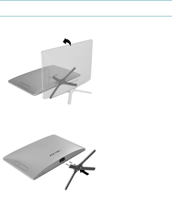
Stand assembly
1.Prepare the computer for disassembly (see Preparation for disassembly on page 13).
2.Position the computer with the rear cover toward you.
 CAUTION: Before positioning the computer with the display assembly facing down, make sure
the work surface is clear of tools, screws, and any other foreign objects. Failure to follow this caution can result in damage to the display assembly.
3.Rotate the top edge of the computer away from you until the display panel lies face down on the work surface.
4.Loosen the two captive screws that secure the stand assembly to the computer, and then remove the stand assembly.
Reverse this procedure to install the stand assembly.
14 Chapter 4 Removal and replacement procedures
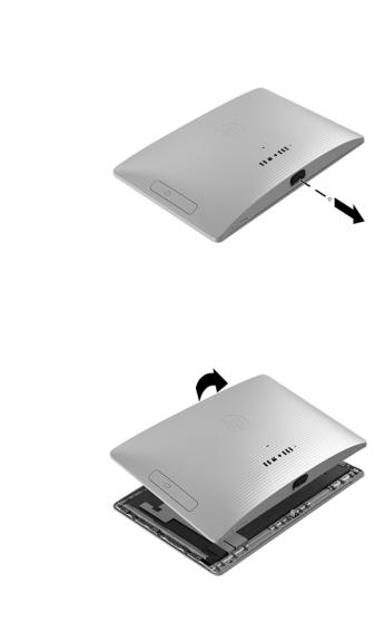
Rear cover
1.Prepare the computer for disassembly (see Preparation for disassembly on page 13).
2.Remove the stand assembly (see Stand assembly on page 14).
3.Remove the Phillips screw that secures the rear cover to the computer.
4.Release the rear cover by detaching the top edge of the cover from the display assembly.
Rear cover 15
5.Remove the rear cover by detaching the bottom edge of the cover from the display assembly, and then swinging the bottom edge up and back until the rear cover rests upside down behind
the display assembly.
Reverse this procedure to install the rear cover.
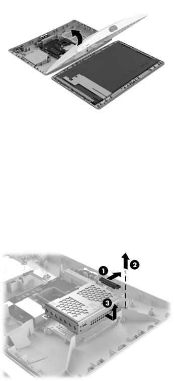
Hard drive
1.Prepare the computer for disassembly (see Preparation for disassembly on page 13).
2.Remove the stand assembly (see Stand assembly on page 14).
3.Remove the rear cover (see Rear cover on page 15).
4.Disconnect the hard drive cable (1) from the hard drive.
5.Remove the slotted Torx screw (2) that secures the hard drive cage to the rear cover.
6.Remove the hard drive cage (3).
7.Remove the four Phillips screws (1) that secure the hard drive to the hard drive cage.
16 Chapter 4 Removal and replacement procedures
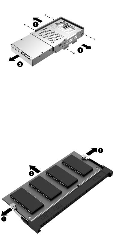
8.Remove the hard drive (2) from the hard drive cage.
Reverse this procedure to install the hard drive and hard drive cage.
Memory module
1.Prepare the computer for disassembly (see Preparation for disassembly on page 13).
2.Remove the stand assembly (see Stand assembly on page 14).
3.Remove the rear cover (see Rear cover on page 15).
4.Spread the retaining tabs (1) on each side of the memory module slot to release the memory module. (The memory module tilts up.)
5.Remove the memory module (2) by pulling it away from the slot at an angle.
Reverse this procedure to install a memory module.
Memory module 17
Optical drive
1.Prepare the computer for disassembly (see Preparation for disassembly on page 13).
2.Remove the stand assembly (see Stand assembly on page 14).
3.Remove the rear cover (see Rear cover on page 15).
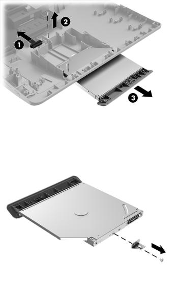
4.Disconnect the optical drive cable (1) from the optical drive.
5.Remove the slotted Torx screw (2) that secures the optical drive to the rear cover.
6.Remove the optical drive (3).
7.Remove the Phillips screw that secures the optical drive bracket to the optical drive, and then remove the optical drive bracket.
Reverse this procedure to reassemble and install the optical drive.
18 Chapter 4 Removal and replacement procedures

5Computer Setup (F10) Utility
Computer Setup (F10) Utilities
Use Computer Setup (F10) Utility to do the following:
●Change settings from the defaults or restore the settings to default values.
●View the system con guration, including settings for processor, graphics, memory, audio, storage, communications, and input devices.
●Modify the boot order of bootable devices such as hard drives, optical drives, or USB flash media devices.
●(Windows 7 only) Establish an Ownership Tag, the text of which is displayed each time the system is turned on or restarted.
●Enter the Asset Tag or property identi cation number assigned by the company to this computer.
●Enable the power-on password prompt during system restarts (warm boots) as well as during power-on.
●Establish an administrator password that controls access to the Computer Setup (F10) Utility and the settings described in this section.
●Establish minimum requirements for valid passwords, including length and required types of characters.
●Secure integrated I/O functionality, including the serial, USB, or audio, or embedded NIC, so that they cannot be used until they are unsecured.
●Enable or disable di erent types of boot sources.
●Con gure features such as Secure Boot, power management, virtualization support, and language and keyboard type used in Setup and POST.
●Replicate the system setup by saving system con guration information on a USB device and restoring it on one or more computers.
●Enable or disable DriveLock security or securely erase a hard drive (when supported by drive).
Using Computer Setup (F10) Utilities
Computer Setup can be accessed only by turning the computer on or restarting the system. To access the Computer Setup Utilities menu, complete the following steps:
1.Turn on or restart the computer.
2.Repeatedly press F10 when the monitor light turns green to access the utility.
You can also press Esc to a menu that allows you to access di erent options available at startup, including the Computer Setup utility.
 NOTE: If you do not press F10 at the appropriate time, you must restart the computer and again repeatedly press F10 when the monitor light turns green to access the utility.
3.A choice of four headings appears in the Computer Setup Utilities menu: Main, Security, Advanced, and UEFI Drivers.
 NOTE: Selecting UEFI Drivers restarts the computer into the 3rd party option ROM management application. You can access this application directly by pressing F3 during startup.
Computer Setup (F10) Utilities 19

4.Use the arrow (left and right) keys to select the appropriate heading. Use the arrow (up and down) keys to select the option you want, then press Enter. To return to the Computer Setup Utilities menu, press Esc.
5.To apply and save changes, select Main > Save Changes and Exit.
●If you have made changes that you do not want applied, select Ignore Changes and Exit.
●To restore settings from the Advanced and Main menus to original values, select Apply Factory Defaults and Exit.
●To restore settings from the Advanced and Main menus to those previously saved by Save Custom Defaults, select Apply Custom Defaults and Exit. If no custom defaults have been saved, then factory defaults are used.
 NOTE: Settings in the Security menu are not modi ed by Apply Defaults. Those values are reset by
Restore Security Settings to Default at the bottom of the Security menu.
 NOTE: Not all settings shown in the following sections are available for all models
 CAUTION: Do NOT turn the computer power OFF while the BIOS is saving the Computer Setup (F10) changes because the settings could become corrupted. It is safe to turn o the computer only after exiting the F10 Setup screen.
20 Chapter 5 Computer Setup (F10) Utility

Computer Setup–Main
 NOTE: Support for speci c Computer Setup options may vary depending on the hardware con guration.
Table 5-1 Computer Setup—Main
Option |
Description |
|
|
|
|
System Information |
Lists all information in following list if Advanced System Information is selected. Lists smaller subset if |
|
|
Basic System Information is selected. |
|
|
● |
Product name |
|
● |
Installed memory size |
|
● |
Processor type |
|
● |
Processor cache size (L1/L2/L3) |
|
● |
Processor speed |
|
● |
MicroCode Revision |
|
● |
Processor Stepping |
|
● |
DIMM size (for each installed module) |
|
● |
System BIOS version |
|
● |
ME Firmware version (Intel only) |
|
● |
Video BIOS version |
|
● |
Super I/O Firmware version |
|
● |
Born On Date |
|
● |
Serial Number |
|
● |
SKU number |
|
● |
UUID (Universally Unique denti er |
|
● |
Asset Tracking Number |
|
● |
Feature Byte |
|
● |
Build ID |
|
● |
Product Family |
|
● |
System Board ID |
|
● |
System Board CT |
|
● |
Integrated MAC Address |
|
|
|
System Diagnostics |
If the hard drive has the HP Advanced Diagnostics installed, the application will launch. If HP Advanced |
|
|
Diagnostics is not installed, then a basic version built into the BIOS will provide the capability to perform |
|
|
the following functions: |
|
|
● |
Memory Test |
|
● |
Hard Drive Check |
|
● |
Language |
|
|
|
Update System BIOS |
Lets you update the system BIOS from www.hp.com or another network server, from a removable USB |
|
|
drive, or from a le located on the hard drive. |
|
|
● |
‘Check HP.com for BIOS Updates’ or ‘Check the Network for BIOS Updates’ |
|
|
The string that appears here depends on the setting in ‘BIOS Update Preferences’. |
Computer Setup (F10) Utilities 21

Table 5-1 Computer Setup—Main (continued)
Option |
Description |
||
|
|
|
|
|
● |
Lock BIOS Version |
|
|
|
If this option is checked, the system is locked to the current BIOS version and updates are not |
|
|
|
allowed. |
|
|
● |
BIOS Update Preferences |
|
|
|
Allows the administrator to select the source of network updates (www.hp.com or another network |
|
|
|
server) and allows con guration of a periodic check for updates, including policies for: |
|
|
|
■ |
Check for updates and prompt the user to accept or reject the update at that time |
|
|
■ |
Check for updates and install all new versions |
|
|
■ |
Check for updates and install only new versions marked important |
|
● |
Network Con guration Settings |
|
|
● |
Update BIOS Using Local Media |
|
|
|
Lets you access les on either USB storage or the hard drive. The HP BIOS Update and Recovery |
|
|
|
application included in BIOS Softpaqs at www.hp.com will copy the BIOS le to the correct location |
|
|
|
on the hard drive or USB device. |
|
|
|
||
System IDs |
Lets you set the following values: |
||
|
● |
Asset Tracking Number |
|
|
● |
Ownership Tag |
|
|
|
||
Replicated Setup |
Backup current settings to USB device |
||
|
Saves system con guration to a formatted USB flash media device. |
||
|
Restore current settings from USB device |
||
|
Restores system con guration from a USB flash media device. |
||
|
|
||
Save Custom Defaults |
Saves the current system con guration settings as the custom default set. |
||
|
|
||
Apply Custom Defaults |
Applies the custom default settings to the computer after rebooting. Does not apply to options in |
||
and Exit |
the Security menu. |
||
|
|
||
Apply Factory Defaults |
Restores the factory system con guration settings to the computer after rebooting. Does not apply to |
||
and Exit |
options in the Security menu. |
||
|
|
||
Ignore Changes and Exit |
Exits Computer Setup without applying or saving any changes. |
||
|
|
||
Save Changes and Exit |
Saves changes to current system con guration, exits Computer Setup, and reboots. |
||
|
|
|
|
22 Chapter 5 Computer Setup (F10) Utility
Loading...