


Liquid Crystal Projector
CP-S370W
USER'S MANUAL
Please read this user's manual thoroughly to ensure correct usage through understanding.
BEDIENUNGSANLEITUNG
Bitte lessen Sie diese Bedienungsanleitung zugunsten der korrekten Bedienung aufmerksam.
MANUEL D'UTILISATION
Nous vous recommandons de lire attentivement ce manuel pour bien assimiler le fonctionnement de l'appareil.
MANUALE D'ISTRUZIONI
Vi preghiamo voler leggere attentamente il manuale d'sitruzioni in modo tale da poter comprendere quanto riportato ai fini di un corretto utilizzo del proiettore.
MANUAL DE USUARIO
Lea cuidadosamente este manual del usuario para poder utilizar corretamente el producto.
GEBRUIKSAANWIJIZING
Lees voor het qebruik alstublieft deze handleiding aandachtig door, om volledig profijt te hebben van de uitgebreide mogelijkheden.
BRUKERHÅNDBOK
Vennligst les denne bruksanvisningen grundig for å være garantert driftssikker bruk.
INSTRUÇÕES DO PROPRIETÁRIO
Para assegurar o uso correto do equipamento, por favor leia atentamente este manual do usuário.
TECHNICAL
REGULATORY NOTICES
PORTGÊS NORSK NEDERLANDS ESPAÑOL ITALIANO FRANÇAIS DEUTSCH ENGLISH
TECHNICAL

Liquid Crystal Projector
USER'S MANUAL
Thank you for purchasing this liquid crystal projector.
WARNING • Please read the accompanying manual “SAFETY INSTRUCTIONS” and this “USER'S MANUAL” thoroughly to ensure correct
usage through understanding. After reading, store this instruction manual in a safe place for future reference.
NOTE • The information in this manual is subject to change without notice.
•The manufacturer assumes no responsibility for any errors that may appear in this manual
•The reproduction, transmission or use of this document or contents is not permitted without express written authority.
TRADEMARK ACKNOWLEDGMENT : PS/2, VGA and XGA are registered trademarks of International Business Machines Corporation. Apple, Mac and ADB are registered trademarks of Apple Computer, Inc. VESA and SVGA are trademarks of the Video Electronics Standard Association. Windows is a registered trademark of Microsoft Corporation. Carefully observe the trademarks and registered trademarks of all companies, even when not mentioned.
CONTENTS
|
Page |
|
Page |
|
FEATURES ....................................... |
2 |
TROUBLESHOOTING .................... |
20 |
|
BEFORE USE ................................... |
2 |
OSD Message ...................................... |
20 |
|
Contents of Package .............................. |
2 |
Indicators Message .............................. |
21 |
|
Part Names............................................. |
3 |
Symptom .............................................. |
22 |
|
Loading the Battery ................................ |
5 |
SPECIFICATIONS........................... |
23 |
|
Fixing the Handle.................................... |
5 |
WARRANTY AND AFTER-SERVICE...... |
24 |
|
INSTALLATION ................................ |
6 |
....................................................................................... |
||
Installation of the Projector and Screen |
6 |
|||
TABLES |
|
|||
Angle Adjustment |
6 |
|
||
Table 1. Installation Reference |
6 |
|||
Cabling |
7 |
|||
Table 2. Cabling |
7 |
|||
Power Connection |
8 |
|||
Table 3. Basic Operations |
10 |
|||
Example of System Setup |
8 |
|||
Table 4. Setup Menu |
12 |
|||
Plug & Play |
8 |
|||
Table 5. Input Menu |
13 |
|||
OPERATIONS |
9 |
|||
Table 6. Image Menu |
14 |
|||
Power ON |
9 |
|||
Table 7. Options Menu |
15 |
|||
Power OFF |
9 |
|||
Table 8. No Signal Menu |
16 |
|||
Basic Operation |
10 |
|||
Table 9. OSD Message |
20 |
|||
Setup Menu |
12 |
|||
Table 10. Indicator Message |
21 |
|||
Input Menu |
13 |
|||
Table 11. Symptom |
22 |
|||
Image Menu |
14 |
|||
Table 12. Specifications |
23 |
|||
Options Menu |
15 |
|||
|
|
|||
No Signal Menu .................................... |
16 |
....................................................................................... |
|
|
MAINTENANCE .............................. |
17 |
For "TECHNICAL" and "REGULATORY |
||
Lamp..................................................... |
17 |
NOTICE", see the end of this manual. |
|
|
Air Filter ................................................ |
19 |
|
|
|
Other Maintenance ............................... |
19 |
|
|
|
ENGLISH
ENGLISH-1
FEATURES
This liquid crystal projector is used to project various computer signals as well as NTSC / PAL / SECAM video signals onto a screen. Little space is required for installation and large images can easily be realized.
Outstanding Brightness
The UHB lamp and high-efficiency optical system assure a high level of brightness.
Partial Magnification Function
Interesting parts of images can be magnified for closer viewing.
Distortion Correction Function
Distortion-free images are quickly available.
Extra-low Noise Function
Acoustic noise level from the unit can be reduced.
BEFORE USE
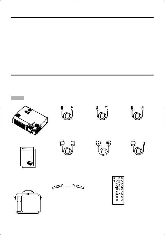
Contents of Package
Make sure all of the following items are included in the package. If anything is missing, please contact your dealer.
NOTE • Keep the original packing material for future reshipment.
Power Cord |
Power Cord |
Power Cord |
(US Type) |
(UK Type) |
(Europe Type) |
Projector
CP-S370W |
|
|
|
USER'S MANUAL |
|
|
|
BEDIENUNGSANLEITUNG |
|
|
|
MANUEL D'UTILISATION |
|
|
|
MANUALE D'ISTRUZIONI |
|
|
|
MANUAL DE USUARIO |
|
|
|
GEBRUIKSAANWIJIZING |
RGB Cable |
Component |
Mouse cable |
INSTRUÇÕES DO PROPRIETÁRIO |
|||
BRUKERHÅNDBOK |
|
|
|
TECHNICAL |
|
Video Cable |
(PS/2) |
REGULATORY NOTICES |
|
||
|
|
(with green lead) |
|
User’s Manual
(this manual)
STANDBY/ON |
VIDEO RGB |
Safety Instructions
Handle
KEYSTONE
MENU
SELECT
MENU POSITION RESET
MAGNIFY |
FREEZE VOLUME |
MUTE
OFF
AUTO |
BLANK |
Remote Controller containing Battery
Carrying Bag
ENGLISH-2

BEFORE USE (continued)
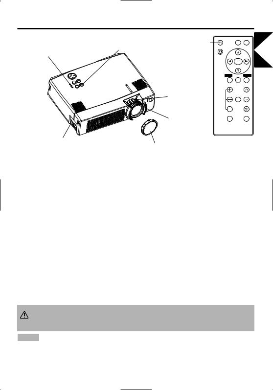
Part Names
Speaker
Zoom Knob
Focus Ring
Handle Hook
Remote Control Sensor
Power Switch |
|
|
Lens |
AC Inlet |
|
(to the Power Cord) |
Lens Cap |
Ventilation Openings |
Foot Adjuster |
|
|
(Intake) |
FRONT/LEFT VIEW OF |
|
|
|
THE PROJECTOR |
ENGLISH
Control Panel (Refer to P.9 "OPERATIONS")
STANDBY/ON Button |
|
|
INPUT Button |
|
KEYSTONE Button |
|
|
LAMP Indicator |
|
|
|
|
|
TEMP Indicator |
|
|
|
|
POWER Indicator |
Foot Adjuster Button |
|
|
RESET Button |
|
|
|
|
|
MENU Button |
Filter Cover |
) |
|
|
|
Air Filter and Intake |
|
|
|
|
( for the Cooling Fan |
|
|
Ventilation Openings |
|
|
|
|
|
(exhaust) |
Rear Foot Adjuster |
|
|
|
|
|
REAR/RIGHT VIEW OF |
Terminal Panel |
||
|
THE PROJECTOR |
(Refer below) |
||
S-VIDEO Terminal |
|
|
|
|
COMPONENT VIDEO |
|
|
|
Remote Control Sensor |
Y Terminal |
|
|
|
|
|
|
|
RGB IN 1 Terminal |
|
CB/PB Terminal |
|
|
|
|
CR/PR Terminal |
|
|
|
RGB IN 2 Terminal |
|
|
|
|
|
VIDEO IN Terminal |
|
1 RGB IN |
2 |
|
AUDIO IN VIDEO IN S-VIDEO IN |
|
|
||
|
|
|
|
|
AUDIO IN R Terminal |
AUDIO 1 |
2 AUDIO OUT USB |
|
|
IN |
|
|
|
|
|
RGB OUT |
CONTROL |
|
|
AUDIO IN L Terminal |
CONTROL Terminal |
|
|
AUDIO IN 1 Terminal |
RGB OUT Terminal |
|
|
AUDIO IN 2 Terminal |
USB Terminal |
|
|
AUDIO OUT Terminal |
TERMINAL PANEL |
|
ENGLISH-3
BEFORE USE (continued)
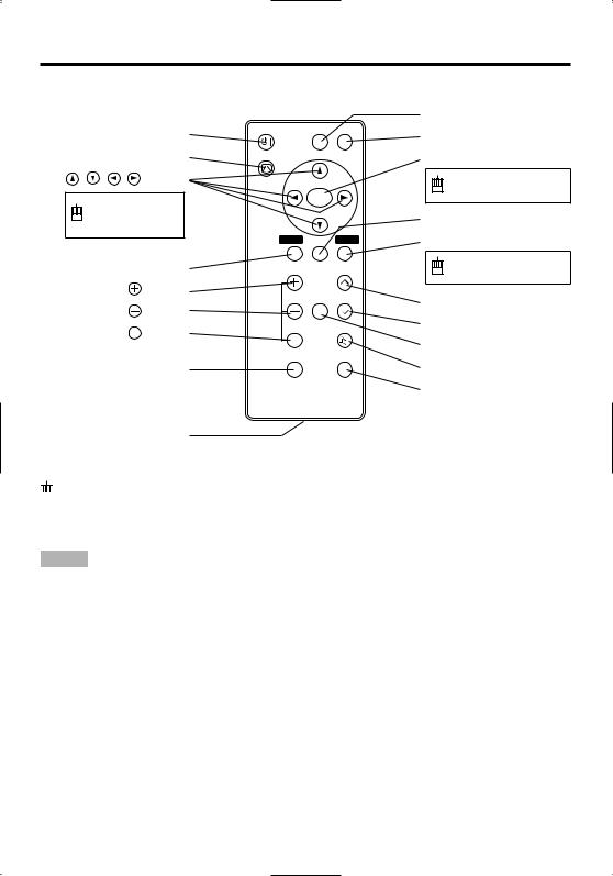
Part Names (continued)
STANDBY/ON Button |
STANDBY/ON |
VIDEO |
RGB |
||
|
|
|
|||
KEYSTONE Button |
KEYSTONE |
|
|
||
|
Button |
|
|
|
|
Used to operate |
|
MENU |
|
||
|
SELECT |
|
|||
|
|
|
|
||
the mouse shift |
|
|
|
||
function . |
|
|
|
|
|
|
|
MENU |
POSITION RESET |
||
MENU Button |
|
|
|
||
MAGNIFY |
Button |
MAGNIFY |
FREEZE |
VOLUME |
|
MAGNIFY |
Button |
||||
|
|
|
|||
MAGNIFY OFF |
Button |
|
|
MUTE |
|
OFF |
|
|
|||
|
|
|
|
||
|
|
AUTO |
|
BLANK |
|
AUTO Button |
|
|
|
||
Battery Holder
REMOTE CONTROLLER
(Refer to P.9 "OPERATIONS")
VIDEO Button
RGB Button
MENU SELECT Button
Used to click the left mouse button.
POSITION Button
RESET Button
Used to click the right mouse button.
VOLUME  Button
VOLUME  Button
FREEZE Button
MUTE Button
BLANK Button


 These functions works when the mouse control function is activated. Remember, the POSITION,VOLUME, KEYSTONE, BLANK ON and MENU ON functions disable the mouse control function.
NOTE • Keep the remote controller away from children and pets.
•Do not give the remote controller any physical impact. Take care not to drop.
•Do not place the heavy objects on the remote controller.
•Do not wet the remote controller or place it on any wet object.
•Do not place the remote controller close to the cooling fan of the projector.
•Do not disassemble the remote controller.
ENGLISH-4
BEFORE USE (continued)
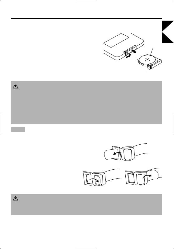
Loading the Battery
First Loading:
In original packing, the battery is installed in the battery holder of |
|
|
the remote controller with protection film (the transparent film some |
|
|
of which is inside the battery folder). Pull out the protection film to |
“+” side |
|
load the battery. |
||
|
Replacing: |
|
|
1. |
See the reverse side of the remote controller. |
|
2. |
Pinch the groove and pull out battery holder as the drawing right. |
Pull out |
3. |
Remove the worn battery. |
|
4. |
Install the new battery with “+” side facing. |
Battery Holder |
5. |
Push in and click the battery holder. |
|
ENGLISH
CAUTION • Incorrect handling of the battery could result in fire or personal injury.The  battery may explode if not handled properly. Be careful in handling the battery according to instructions of accompaning manual "SAFETY INSTRUCTIONS"and this manual.
•Use the 3V micro lithium battery type no.CR2025 only.
•When loading the battery, make sure the plus and minus terminals are correctly oriented as indicated in the remote controller.
•When you dispose the battery, you should obey the law in the relative area or country.
•Keep the battery away from children and pets.
•When not to be used for an extended period, remove the battery from the remote controller.
NOTE Replace the batteries when remote control transmitter operation becomes difficult.
Fixing the Handle
Fix the enclosed handle if you need.
1.Raise up the handle hook, and pass one end of the handle through the hole of handle hook.
2.Buckle the end of the handle, as the right drawing.
3. Fix the other end of the handle to the other handle |
2 |
hook in the same way. |
|
1
CAUTION • Make sure the handle is fixed before carrying the projector with the handle. If the projector should be dropped from the handle should be off,
it could result in an injury, and continued use could result in fire or electrical shock. Do not flourish the projector with the handle.
ENGLISH-5
INSTALLATION
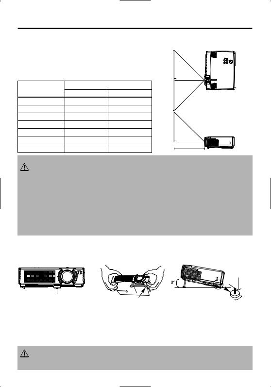
Installation of the Projector and Screen
Refer to the drawing and table below for determining of the screen size and projection distance.
The projection distances shown in the table below are for full size (800 x 600 dots).
a: Distance from the projector to the screen. (±10%)
Table 1. Installation Reference |
|
|
|
|
|||
Screen size |
|
a [inches (m)] |
|
|
|
||
[inches (m)] |
Min. |
Max. |
|
Top View |
|||
40 |
(1.0) |
62 |
(1.6) |
82 |
(2.1) |
|
|
60 |
(1.5) |
94 |
(2.4) |
123 |
(3.1) |
|
|
80 |
(2.0) |
127 |
(3.2) |
164 |
(4.2) |
|
|
100 |
(2.5) |
160 |
(4.1) |
205 |
(5.2) |
|
|
120 |
(3.0) |
192 |
(4.9) |
246 |
(6.3) |
|
|
150 |
(3.8) |
241 |
(6.1) |
308 |
(7.8) |
|
|
200 |
(5.0) |
323 |
(8.2) |
411 (10.4) |
a |
Side View |
|
|
|
|
|
|
|
||
CAUTION • Install the projector in a suitable environment according to instructions of the accompanying manual “SAFETY INSTRUCTIONS” and this manual.
• When you fix this unit with a metal tool and the like, you must connect it with ground wire; otherwise, fire or electric shock can result.
Connect the ground terminal of AC inlet of this unit with the ground terminal provided at the building using an optional three-core power-supply cord.
•Please basically use liquid crystal projector at the horizontal position. If you use liquid crystal projector by the lens up position, the lens down position and the side up position, this may cause the heat inside to build up and become the cause of damage. Be especially careful not to install it with ventilation holes blocked.
•Do not install LCD projector in smoke effected environment. Smoke residue may buildup on critical parts (i.e.LCD panel, Lens Assy etc.).
Angle Adjustment
Use the foot adjusters on the bottom of the projector to adjust the projection angle. It is variable within 0˚ to 9˚ approximately.
Foot Adjuster |
Press the foot adjuster button |
Rear Foot Adjuster
1.Lift up the front side of the projector, and pressing the foot adjuster button, adjust the projection angle.
2.Release the button to lock at the desired angle.
3.Turn the rear foot adjuster to adjust the left-right slope. Do not force the foot adjuster screws. This could damage the adjusters or cause the lock to fail.
CAUTION • Do not release the foot adjuster button unless the projector is being held; otherwise, the projector could overturn or the fingers could get caught and cause
personal injury.
ENGLISH-6
INSTALLATION (continued)
Cabling
Refer to the table below for connecting each terminal of the projector to each device.
Table 2. Cabling
Function |
Terminal |
Cable |
|
|
|
|
|
RGB input |
RGB IN 1 |
Accessory or optional RGB cable with D- |
|
|
|||
RGB IN 2 |
|||
|
sub 15-pin shrink jack and inch thread |
||
|
|
screws |
|
RGB output |
RGB OUT |
||
|
|||
|
|
|
|
|
AUDIO IN 1 |
|
|
Audio input |
(interlocked with RGB IN 1) |
Optional audio cable with stereo mini jack |
|
|
|||
(from the computer) |
AUDIO IN 2 |
||
|
|||
|
|
||
|
(interlocked with RGB IN 2) |
|
|
|
|
|
|
PS/2 mouse control |
|
Accessory PS/2 mouse cable |
|
|
|
|
|
ADB mouse control |
CONTROL |
Optional ADB mouse cable |
|
|
|
||
Serial mouse control |
Optional Serial mouse cable |
||
|
|||
|
|
|
|
RS-232C communication |
|
Optional RS-232C cable |
|
|
|
|
|
USB mouse control |
USB |
Optional USB cable |
|
|
|
|
|
S-video input |
S-VIDEO IN |
Optional S-video cable with mini DIN 4-pin |
|
jack |
|||
|
|
||
|
|
|
|
Video input |
VIDEO IN |
Optional video/audio cable |
|
|
|
|
|
|
COMPONENT VIDEO Y |
|
|
|
|
|
|
Component video input |
COMPONENT VIDEO CB/PB |
Accessory component video cable |
|
|
|
|
|
|
COMPONENT VIDEO CR/PR |
|
|
|
|
|
|
Audio input |
AUDIO IN L |
Optional video/audio cable or optional |
|
|
|||
(from video equipment) |
AUDIO IN R |
audio cable with RCA jack |
|
|
|
|
|
Audio output |
AUDIO OUT |
Optional audio cable with stereo mini jack |
|
|
|
|
CAUTION • Incorrect connecting could result in fire or electrical shock. Please read this manual and the separate “SAFETY INSTRUCTIONS”.
•Before connecting, turn off to all devices to be connected, except for the USB cable.
•The cables may have to be used with the core set to the projector side. Use the cables which are included with the projector or specified.
NOTE • Before connecting, read instruction manuals of the devices to be connected, and make sure that the projector is compatible with the device.
•Secure the screws on the connectors and tighten.
•For some RGB input modes, the optional Mac adapter is necessary.
•Some computers may have multiple display screen modes. Use of some of these modes will not be possible with this projector.
•Refer to the “TECHNICAL” section for the pin assignment of connectors and RS-232C communication data.
ENGLISH
ENGLISH-7
INSTALLATION (continued)
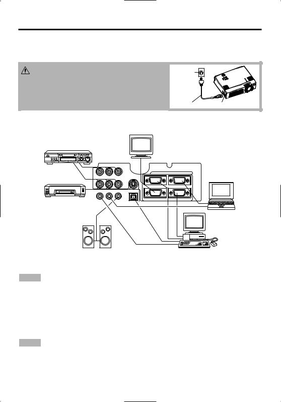
Power Connection
Use the correct one of the enclosed power cords depending on the power outlet to be used. Connect the AC inlet of the projector to the power outlet firmly by the power cord.
CAUTION • Be carful in handling the power cord according to instructions of the
accompanying manual "SAFETY INSTRUCTIONS" and this manual.
• Connect the power cord firmly. Avoid using a loose, unsound outlet or contact failure.
Power
outlet
Power Cord |
AC Inlet |
Example of system setup
Display
Monitor
COMPONENT VIDEO
DVD Player
1 |
RGB IN |
2 |
AUDIO IN VIDEO IN S-VIDEO IN
S-Video Tape
Recorder
AUDIO 1 2 AUDIO OUT USB
IN
RGB OUT |
CONTROL |
Computer
(notebook type)
Speaker with |
Computer |
amplifier |
(desktop type) |
NOTE • When connecting with notebook computer, set to valid the RGB external image output (setting CRT display or simultaneous display of LCD and CRT). Please read instruction manual of the notebook for more information.
Plug & Play
This projector is VESA DDC 1/2B compatible. Plug & play is possible by connecting to a computer that is VESA DDC (Display Data Channel) compatible.
Please use this function by connecting the accessory RGB cable with RGB IN 1 terminal (DDC 1/2B compatible). Plug & play may not operate by other connecting.
NOTE • Plug & play is a system configured with peripheral equipment including a computer and display, and an operating system.
•This projector is recognized as a plug & play monitor. Use the standard display drivers.
•Plug & play may not operate by the computer to connect. Use the RGB IN 2 terminal if plug & play does not operate correctly.
ENGLISH-8
OPERATIONS
POWER Indicator
STANDBY/ON Button |
STANDBY/ |
ON Button |
STANDBY/ON |
VIDEO RGB |
KEYSTONE
MENU
SELECT
MENU POSITION RESET
ENGLISH
Zoom Knob
Focus Ring
Power Switch
Lens Cap
MAGNIFY |
FREEZE VOLUME |
|
MUTE |
OFF |
|
AUTO |
BLANK |
Power ON
1.Check that the power cord is connected correctly.
2.Set the power switch to [ | ]. The standby mode is selected, and the POWER indicator is turned to
orange.
3.Press the STANDBY/ON button  on the control panel or the remote control transmitter. Warm-up begins and the POWER indicator blinks in green.
4.The POWER indicator ceases blinking and turns to green when power is on. Open the slide lens door.
5.Adjust picture size using the zoom knob.
6.Adjust focus using the focus ring .
Power OFF
1.Press the STANDBY/ON button  on the control panel or the remote controller. Then,the message "Power off?" will appear on the screen, and the message will disappear by any operation
or no operation for 5 seconds. During this message indication, press the STANDBY/ON  button again. The projector lamp is extinguished and lamp cooling begins. The POWER indicator
blinks orange during lamp cooling. Pressing the STANDBY/ON button  has no effect while the POWER indicator is blinking.
2.The system assumes the Standby mode when cooling is complete, and the POWER indicator ceases blinking and changes to orange. Check that the indicator is orange and set the power switch to [O].
3.The POWER indicator is extinguished when power is off. Do not forget to close the lens door.
WARNING • Please read this manual, and the separate “SAFETY INSTRUCTIONS” thoroughly before using the equipment. Always ensure that
the equipment is used safely.
NOTE • Except in emergencies, follow the above-mentioned procedure for turning power off. Incorrect procedure will reduce the life of the projector lamp and LCD panel.
•To prevent any troble, turn on/off the projector when the computer or video tape recorder is OFF. Providing a RS-232C cable is connected, turn on the computer before the projector.
•When a projector continues projecting the same image, the image may remain as an afterimage. Please do not project the image same for a long time.
ENGLISH-9
OPERATIONS (continued)
Basic Operation
The basic operations shown in Table 3 is performed from the supplied remote control transmitter or the projector control panel. Items indicated by (*) may be used from the control panel.
Table 3 . Basic Operation
Item |
Description |
Select Input Signal (*) : Press the INPUT button.
RGB IN 1→RGB IN 2→ VIDEO IN → S-VIDEO IN → COMPONENT VIDEO (→ RGB IN 1)
Select RGB Input : Press the RGB button.
VIDEO IN / S-VIDEO IN / COMPONENT VIDEO → RGB IN 1 / RGB IN 2 INPUT RGB IN 1 → RGB IN 2 (→ RGB IN 1)
SELECT Select Video Input : Press the VIDEO button.
RGB IN 1 / RGB IN 2 → VIDEO IN / S-VIDEO IN / COMPONENT VIDEO VIDEO IN → S-VIDEO IN → COMPONENT VIDEO (→ VIDEO IN)
• The selected signal name is displayed for approximately 3 seconds when the input signal is changed.
Set/Clear Position Adjustment Mode : Press the POSITION button.
The [  ] icon is displayed in the POSITION mode.
|
Image Position Adjustment: Press the , |
, and buttons in the |
|
POSITION |
POSITION mode. |
|
|
• Valid only in the MAGNIFY mode with a video signal is input. |
|||
|
|||
|
• After approximately 10 seconds of inactivity the [ |
] icon is extinguished and the |
|
|
POSITION mode is cleared automatically. |
|
|
|
• , , and buttons may operate as the mouse control button. Refer to page 4. |
||
Initialise Each Item : Select an item and press the RESET button.
Initialise Position Adjustment : Press the RESET button and the RESET (*) POSITION mode. This function is valid only when RGB signal is input.
•Valid except for the VOLUME, LANGUAGE and H PHASE.
•The RESET button may operate as the mouse control button. Refer to page 4.
|
Set MAGNIFY Mode : Press the MAGNIFY |
button. |
||||
|
Move Magnified Area : Run the POSITION in the MAGNIFY mode. |
|||||
|
Adjust Magnification : Press the MAGNIFY |
/ |
|
|
button in MAGNIFY |
|
|
|
|
||||
MAGNIFY mode. |
|
|
|
|
||
|
Clear MAGNIFY Mode : Press the MAGNIFY OFF |
button. |
||||
|
• The MAGNIFY mode is cleared by running or setting the AUTO, ASPECT, INPUT |
|||||
|
SELECT or VIDEO, or by changing the input signal. |
|
|
|
|
|
|
|
|||||
|
Set/Clear FREEZE Mode : Press the FREEZE button. The [II] icon is |
|||||
|
displayed, and the image frozen, in the FREEZE mode. |
|||||
FREEZE |
• The FREEZE mode is cleared by running or setting POSITION, VOLUME, MUTE, |
|||||
Automatic Adjustment, BLANK ON/OFF, or MENU ON/OFF, or by changing the |
||||||
|
||||||
|
input signal. |
|
|
|
|
|
|
• Do not forget to clear frozen static images. |
|
|
|
|
|
NOTE • Use the remote control transmitter at a distance of approximately 5m from the sensor on the front of the projector, and within a range of 30° left-right. Strong light and obstacles will interfere with operation of the remote control transmitter.
ENGLISH-10

OPERATIONS (continued)
Items indicated by (*) may be used from the control panel.
Table 3. Basic Operation (continued)
Item |
Description |
|
VOLUME |
Volume Adjustment : Press the VOLUME / button. |
|
|
|
|
MUTE |
Set/Clear Mute Mode : Press the MUTE button. No sound is heard in the |
|
MUTE mode. |
||
|
||
|
|
|
|
Automatic Adjustment at RGB Input : Press the AUTO button. Horizontal |
|
|
position(H.POSIT), vertical position (V.POSIT),clock phase (H.PHASE), and |
|
|
horizontal size(H.SIZE) are automatically adjusted. Use with the window at |
|
AUTO |
maximum size in the application display. |
|
Automatic Adjustment at Video Input : Press the AUTO button. A signal |
||
|
||
|
type appropriate for the input signal is selected automatically. Valid only |
|
|
when AUTO is set for VIDEO on the menu. |
|
|
• This operation requires approximately 10 seconds. It may not function correctly with |
|
|
some input signals. |
|
|
|
|
BLANK |
Set/Clear Blank Mode: Press the BLANK button. No image is displayed in |
|
ON/OFF |
the Blank mode. The screen color is as set in BLANK on the Image menu. |
|
|
|
|
MENU |
Menu Display Start/Stop: Press the MENU button. |
|
• The menu display is terminated automatically after approximately 10 seconds of |
||
ON/OFF (*) |
||
|
inactivity. |
Select Menu Type: Press the MENU SELECT button. Allows the user to select the normal menu or the single menu. Only the selected item is displayed on the single menu, and other items are displayed with the  and
and  buttons as with the normal menu.
|
• Valid only when the Setup menu is used. Push the MENU SELECT button after |
|||
MENU |
selecting items such as "BRIGHTNESS". |
|
|
|
• The MENU SELECT button may operate as the mouse control button. Refer to |
||||
SELECT |
page 4. |
|
|
|
|
Normal menu |
Single menu |
||
|
|
(MENU SELECT) |
|
|
|
SETUP INPUT IMAGE OPT. |
|
|
|
|
BRIGHT |
0 |
|
|
|
CONTRAST |
-2 |
|
|
|
V POSIT |
100 |
|
|
|
H POSIT |
100 |
|
|
|
H PHASE |
+1 |
|
|
|
H SIZE |
800 |
|
|
|
COLOR BAL R |
0 |
|
|
|
COLOR BAL B |
0 |
|
|
|
ASPECT |
|
CONTRAST |
-2 |
KEYSTONE Set / Clear KEYSTONE Mode : Press the KEYSTONE  button. (*) Adjust KEYSTONE : Press the
  /
/  button.
ENGLISH
ENGLISH-11
 Loading...