


CB6Y

HITACHI
Model
Modèle
Modelo
CB6Y
10″ Band Saw
Scie à ruban de 10 po
Sierra de Banda de 10 pulg.
INSTRUCTION MANUAL AND SAFETY INSTRUCTIONS
WARNING
Improper and unsafe use of this power tool can result in death or serious bodily injury!
This manual contains important information about product safety. Please read and understand
this manual before operating the power tool. Please keep this manual available for others
before they use the power tool.
Hitachi Koki
MANUEL D’INSTRUCTIONS ET CONSIGNES DE SÉCURITÉ
AVERTISSEMENT
L’utilisation inadéquate et non sécuritaire de cet outil électrique peut entraîner la mort ou des
blessures graves! Ce manuel contient des informations importantes sur la sécurité. Veuillez
lire et comprendre ce manuel avant d’utiliser l’outil électrique. Veuillez garder ce manuel
disponible pour les autres utilisateurs, avant qu’ils utilisent cet outil électrique.
MANUAL DE INSTRUCCIONES E INSTRUCCIONES DE SEGURIDAD
ADVERTENCIA
¡El uso inadecuado y no seguro de esta herramienta eléctrica puede ocasionar la muerte o
lesiones corporales graves! Este manual contiene información importante sobre la seguridad
del producto. Por favor lea y entienda este manual antes de usar la herramienta eléctrica.
Por favor mantenga disponible este manual para que otros puedan leerlo antes de usar la
herramienta eléctrica.

– 2 –
SECTION Page
Product Specifications..........................................................3
Safety ...................................................................................4
Accessories and Attachments ..............................................7
Carton Contents ...................................................................7
Know Your Band Saw ...........................................................9
Glossary of Terms...............................................................10
SECTION Page
Assembly and Adjustments ................................................11
Operation............................................................................15
Maintenance.......................................................................17
Troubleshooting Guide........................................................18
Parts List.............................................................................57
TABLE OF CONTENTS
HITACHI AUTHORIZED SERVICE CENTERS
Service under this warranty is available from Hitachi Koki U.S.A., Ltd. at:
IN THE U.S.A.
3950 Steve Reynolds Blvd., Norcross, GA 30093
9409 Owensmouth Ave., Chatsworth, CA 91311
OR CALL: (800) 546-1666 for a service center nearest you.
IN CANADA
6395 Kestrel Road, Mississauga, ON L5T 1Z5
OR CALL: (800) 970-2299 for a service center nearest you.
English
SECTION Page
Spécifications du produit ....................................................21
Sécurité ..............................................................................22
Accessoires et équipements...............................................25
Contenu du carton..............................................................25
Connaître sa scie à ruban ..................................................27
Glossaire des termes .........................................................28
SECTION Page
Assemblage et ajustements ...............................................29
Fonctionnement..................................................................33
Entretien .............................................................................35
Guide de dépannage..........................................................36
Liste des pièces..................................................................57
TABLE DES MATIÈRES
CENTRES DE SERVICE AUTORISÉS D’HITACHI
Le service en vertu de cette garantie est disponible de Hitachi Koki U.S.A., Ltd,
aux emplacements suivants :
AUX É-U
3950 Steve Reynolds Blvd., Norcross, GA 30093
9409 Owensmouth Ave., Chatsworth, CA 91311
OU APPELER : (800) 546-1666 pour contacter un centre
de service le plus près de votre domicile.
AU CANADA
6395 Kestrel Road, Mississauga, ON L5T 1Z5
OU APPELER : (800) 970-2299 pour contacter un centre
de service le plus près de votre domicile.
Français
SECCION Página
Especificaciones del producto............................................39
Seguridad ...........................................................................40
Accesorios y aditamentos ..................................................43
Contenido de la caja...........................................................43
Conozca su sierra de banda...............................................45
Glosario de términos ..........................................................46
SECCION Página
Montaje y ajustes................................................................47
Operación...........................................................................51
Mantenimiento....................................................................53
Guía de identificación de problemas ..................................54
Lista de partes....................................................................57
CONTENIDO
CENTROS DE SERVICIO AUTORIZADO DE HITACHI
El servicio de mantenimiento y reparación bajo esta garantía está disponible a través de
Hitachi Koki U.S.A., Ltd. en:
EN EE.UU.
3950 Steve Reynolds Blvd., Norcross, GA 30093
9409 Owensmouth Ave., Chatsworth, CA 91311
O LLAME AL: (800) 546-1666 para averiguar cuál es el
centro de servicio más cercano a usted.
EN CANADA
6395 Kestrel Road, Mississauga, ON L5T 1Z5
O LLAME AL: (800) 970-2299 para averiguar cuál es el
centro de servicio más cercano a usted.
Español

English
– 3 –
PRODUCT SPECIFICATIONS
MOTOR
Power Source...................120 V, AC, 60 HZ,
4.0 AMPS.
Speeds Low .....................3600 FPM
(Feet Per Minute)
Horsepower......................1/3 HP (Continuous Duty)
Cutting Capacity
Throat ..............................9 3/8″
Height ..............................5″
Blade
Width................................1/4″, 3/8″
Length..............................63 1/2″
Table
Size..................................11 3/4″ x 11 3/4″
Tilt .........................................0° - 45° Left
DUST COLLECTION................Ye s
NET WEIGHT............................68LB (30.6 kg)
To avoid electrical hazards, fire hazards, or damage to the
tool, use proper circuit protection.
Use a separate electrical circuit for your tools.
Your Band Saw is wired at the factory for 120V operation.
Connect to a 120V, 15 AMP branch circuit and use a 15 Amp
time delay fuse or circuit breaker. To avoid shock or fire,
replace power cord immediately if it is worn, cut or
damaged in any way.
WARNING
Some dust created by power sanding, sawing, grinding, drilling and other construction activities contains chemicals
known to the state of California to cause cancer, birth defects or other reproductive harm. Some examples of these
chemicals are:
• Lead from lead-based paints
• Crystalline silica from bricks, cement and other masonry products
• Arsenic and chromium from chemically treated lumber
Your risk from these exposures varies, depending on how often you do this type of work. To reduce your exposure to
these chemicals, work in a well-ventilated area and work with approved safety equipment such as dust masks that are
specially designed to filter out microscopic particles.
WARNING
SAVE THESE INSTRUCTIONS

GENERAL SAFETY INSTRUCTIONS
BEFORE USING THE BAND SAW
Safety is a combination of common sense, staying alert and
knowing how to use this Band Saw.
To avoid mistakes that could cause serious injury, do not plug
the Band Saw in until you have read and understood the
following:
1. READ and become familiar with the entire Operator’s
Manual. LEARN the tool’s application, limitations and
possible hazards.
2. KEEP GUARDS IN PLACE and in working order.
3. REMOVE ADJUSTING KEYS AND WRENCHES.
Form a habit of checking to see that keys and adjusting
wrenches are removed from the tool before turning ON.
4. KEEP WORK AREA CLEAN. Cluttered areas and
benches invite accidents.
5. DON’T USE IN DANGEROUS ENVIRONMENT. Don’t
use power tools in damp or wet locations, or expose
them to rain. Keep work area well lighted.
6. KEEP CHILDREN AWAY. All visitors should be kept
at a safe distance from work area.
7. MAKE WORKSHOP CHILDPROOF with padlocks,
master switches, or by removing starter keys.
8. DON’T FORCE THE TOOL. It will do the job better and
safer at the rate for which it was designed.
9. USE THE RIGHT TOOL. Do not force tool or attachment
to do a job for which it was not designed.
10. USE PROPER EXTENSION CORD. Make sure your
extension cord is in good condition. When using an
extension cord, be sure to use one heavy enough to
carry the current your product will draw. An undersized
cord will result in a drop in line voltage and in loss of
power that will cause the tool to overheat. The table on
page 6 shows the correct size to use depending on cord
length and nameplate ampere rating. If in doubt, use the
next heavier gauge. The smaller the gauge number, the
heavier the cord.
11. WEAR PROPER APPAREL. Do not wear loose clothing,
gloves, neckties, rings, bracelets, or other jewelry that
may get caught in moving parts. Non-slip footwear is
recommended. Wear protective hair covering to contain
long hair.
12. ALWAYS WEAR EYE PROTECTION. Any Band Saw
can throw foreign objects into the eyes that could cause
permanent eye damage. ALWAYS wear Safety Goggles
(not glasses) that comply with ANSI Safety Standard
Z87.1. Everyday eyeglasses have only impact-resistance
lenses. They ARE NOT safety glasses. Safety Goggles
are available at HITACHI.
NOTE: Glasses or goggles not in compliance with
ANSI Z87.1 could cause serious injury.
13. WEAR A FACE MASK OR DUST MASK. Sawing
operation produces dust.
14. SECURE WORK. Use clamps or a vise to hold work
when practical. It’s safer than using your hand and it
frees both hands to operate tool.
15. DISCONNECT TOOLS before servicing; when changing
accessories such as blades, bits, cutters, and the like.
16. REDUCE THE RISK OF UNINTENTIONAL STARTING.
Make sure switch is in OFF position before plugging in.
17. USE RECOMMENDED ACCESSORIES. Consult the
Operator’s Manual for recommended accessories. The
use of improper accessories may cause serious injury.
18. NEVER STAND ON TOOL. Serious injury could occur if
the tool is tipped or if the cutting tool is unintentionally
contacted.
19. CHECK FOR DAMAGED PARTS. Before further use of
the tool, a guard or other part that is damaged should
be carefully checked to determine that it will operate
properly and perform its intended function – check for
alignment of moving parts, binding of moving parts,
breakage of parts, mounting, and any other conditions
that may affect its operation. A guard or other part that
is damaged should be properly repaired or replaced.
20. NEVER LEAVE TOOL RUNNING UNATTENDED. TURN
POWER “OFF”. Don’t leave tool until it comes to a
complete stop.
21. DON’T OVERREACH. Keep proper footing and balance
at all times.
22. MAINTAIN TOOLS WITH CARE. Keep tools sharp and
clean for best and safest performance. Follow instructions
for lubricating and changing accessories.
23. DO NOT use power tools in the presence of flammable
liquids or gases.
24.
DO NOT OPERATE the tool if you are under the
influence of any drugs, alcohol or medication that could
affect your ability to use the tool properly.
25. ALWAYS operate the Band Saw in a well-ventilated area
and provide for proper dust removal. Use dust collection
systems whenever possible. Dust generated from certain
materials can be hazardous to your health.
WARNING
English
– 4 –
SAFETY

SPECIFIC SAFETY INSTRUCTIONS FOR
BAND SAWS
1. TO AVOID INJURY from unexpected movement, make
sure the saw is on a firm, level surface, properly secured
to prevent rocking. Make sure there is adequate space
for operating. Bolt the saw to a support surface to
prevent slipping, walking, or sliding during operation.
2. TURN the saw OFF and unplug the saw before moving it.
3. USE THE CORRECT size and style blade.
4. USE blades rated at 3600 FPM or greater.
5. MAKE SURE the blade teeth point down and towards the
table.
6. BLADE GUIDES, SUPPORT BEARINGS, AND BLADE
TENSION must be properly adjusted to avoid accidental
blade contact and to minimize blade breakage. To maximize
blade support, always adjust the upper blade guide and
blade guard so that it is 1/8 inch above the workpiece.
7. TABLE LOCK HANDLE should be tight.
8. USE EXTRA CAUTION with large, very small or
awkward workpieces.
9. USE EXTRA SUPPORTS to prevent workpieces from
sliding off the tabletop. Never use another person to
support the workpiece.
10. WORKPIECES must be secured so they don’t twist,
rock, or slip while being cut.
11. PLAN intricate and small work carefully to avoid pinching
the blade. Avoid awkward operation and hand positions
to prevent accidental contact with the blade.
12. SMALL PIECES should be secured with jigs or fixtures.
Do not hand hold pieces that are so small your fingers
are under the blade guard.
13. SUPPORT round work properly (with a V-block or
clamped to the miter gauge) to prevent it from rolling
and the blade from biting.
14. CUT only one workpiece at a time. Make sure the table is
clear of everything except the workpiece and its guides
before you turn the saw on.
15. ALWAYS WATCH the saw run before each use. If there
is excessive vibration or unusual noise, stop immediately.
Turn the saw OFF. Unplug it immediately. Do not start
the saw again until the problem has been located and
corrected.
16. TO FREE any jammed material, turn the switch OFF.
Remove the switch key and unplug the saw. Wait for all
moving parts to stop before removing jammed material.
17. DON’T LEAVE the work area until all moving parts are
stopped. To childproof the workshop, shut OFF the power
to master switches and remove the switch key from the
band saw. Store it in a safe place, away from children.
For your own safety, read the entire instruction manual before
operating the band saw.
1. Wear eye protection.
2. Do not wear gloves, necktie, or loose clothing.
3. Make sure the saw is on a firm level surface and properly
secured.
4. USE ONLY THE RECOMMENDED ACCESSORIES.
5. Use extra caution with very large, very small, or awkward
workpieces.
6. Keep hands away from the blade at all times to prevent
accidental injury.
7. Do not remove jammed cutoff pieces until the blade has
stopped.
8. Maintain proper adjustment of blade tension, blade
guides and thrust bearings.
9. Adjust upper guide to just clear the workpiece.
10. Hold the workpiece firmly against the table.
ELECTRICAL REQUIREMENTS
POWER SUPPLY AND MOTOR SPECIFICATIONS
To avoid electrical hazards, fire hazards, or damage to the
tool, use proper circuit protection. Use a separate electrical
circuit for your tools. Your saw is wired at the factory for 120V
operation. Connect to a 120V, 15 Amp circuit and use a
15 Amp time delay fuse or circuit breaker. To avoid shock or
fire, if power cord is worn or cut, or damaged in any way,
have it replaced immediately.
GROUNDING INSTRUCTIONS
This tool must be grounded while in use to protect the
operator from electrical shock.
IN THE EVENT OF A MALFUNCTION OR BREAKDOWN,
grounding provides a path of least resistance for electric
current and reduces the risk of electric shock. This tool is
equipped with an electric cord that has an equipment-grounding
conductor and a grounding plug. The plug MUST be plugged
into a matching receptacle that is properly installed and
grounded in accordance with ALL local codes and ordinances.
DO NOT MODIFY THE PLUG PROVIDED. If it will not fit the
receptacle, have the proper receptacle installed by a qualified
electrician.
IMPROPER CONNECTION of the equipment-grounding
conductor can result in risk of electric shock. The conductor
with green insulation (with or without yellow stripes) is the
equipment-grounding conductor. If repair or replacement of
the electric cord or plug is necessary, DO NOT connect the
equipment-grounding conductor to a live terminal.
CHECK with a qualified electrician or service person if you
do not completely understand the grounding instructions,
or if you are not sure the tool is properly grounded.
WARNING
WARNING
WARNING
English
– 5 –
USE ONLY 3-wire extension cords that have 3-prong
grounding plugs and 3-pole receptacles that accept the
tool’s plug. Repair or replace damaged or worn cord
immediately.
Use a separate electrical circuit for your tools. This circuit
must not be less than #12 wire and should be protected with
a 15 Amp time delay fuse. Before connecting the motor to the
power line, make sure the switch is in the OFF position and
the electric current is rated the same as the current stamped
on the motor nameplate. Running at a lower voltage will
damage the motor.
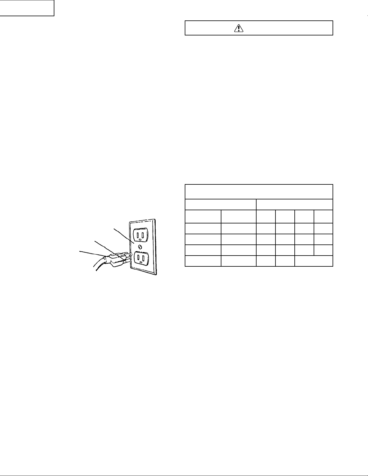
This tool is intended for use on a circuit that has a receptacle
like the one illustrated in Figure A showing a 3-prong
electrical plug and receptacle that has a grounding conductor.
If a properly grounded receptacle is not available, an adapter
(Figure B) can be used to temporarily connect this plug to
a 2-contact ungrounded receptacle. The adapter (Figure B)
has a rigid lug extending from it that MUST be connected
to a permanent earth ground, such as a properly grounded
receptacle box. THE TEMPORARY ADAPTER SHOULD
BE USED ONLY UNTIL A QUALIFIED ELECTRICIAN CAN
INSTALL A PROPERLY GROUNDED OUTLET. The
Canadian Electrical Code prohibits the use of adapters.
CAUTION: In all cases, make certain the receptacle is
properly grounded. If you are not sure, have a qualified
electrician check the receptacle.
This Band Saw is for indoor use only. Do not expose to rain
or use in damp locations.
GUIDELINES FOR EXTENSION CORDS
USE PROPER EXTENSION CORD. Make sure your extension
cord is in good condition. When using an extension cord,
be sure to use one heavy enough to carry the current your
product will draw. An undersized cord will cause a drop in line
voltage, resulting in loss of power and cause overheating.
The table below shows the correct size to use depending on
cord length and nameplate ampere rating. If in doubt, use
the next heavier gauge. The smaller the gauge number
the heavier the cord.
Be sure your extension cord is properly wired and in good
condition. Always replace a damaged extension cord or have
it repaired by a qualified person before using it. Protect your
extension cords from sharp objects, excessive heat and
damp or wet areas.
MINIMUM GAUGE FOR EXTENSION CORDS (AWG)
(When using 120 Volt only)
Ampere Rating Total length in feet
More Than
Not
More Than
25′ 50′ 100′ 150′
0 6 18 16 16 14
6 10 18 16 14 12
10 12 16 16 14 12
12 16 14 12 Not Applicable
WARNING
English
– 6 –
Properly Grounded
3-Prong Receptacle
Grounding Prong
3-Prong Plug
Grounding Lug
Adapter
3-Prong Plug
Make Sure This
is Connected to
a Known Ground
2-Prong Receptacle
Fig. A
Fig. B

UNPACKING AND CHECKING CONTENTS
Carefully unpack the Band Saw and all its parts, and compare
against the illustration following. Place the saw on a secure
surface and examine it carefully.
• To avoid injury from unexpected starting, do not plug
the power cord into a power source receptacle during
unpacking and assembly. This cord must remain
unplugged whenever you are assembling or adjusting
the saw.
• Although compact, this saw is heavy. To avoid back injury,
get help whenever you have to lift the saw.
• If any part is missing or damaged, do not plug the band
saw in until the missing or damaged part is replaced,
and assembly is complete.
TABLE OF LOOSE PARTS
ITEM DESCRIPTION QUANTITY
BAND SAW:
A. Band Saw with Motor 1
B. Miter Gauge 1
C. Crank Handle 1
D. Pointer 1
E. Bag Clamp 1
F. Dust Bag 1
G. Battery 1
WARNING
English
– 7 –
ACCESSORIES AND ATTACHMENTS
RECOMMENDED ACCESSORIES
To avoid injury:
• Use only accessories recommended for this Band Saw.
• Follow instructions that accompany accessories. Use of
improper accessories may cause hazards.
• Use only accessories designed for this Band Saw to
avoid injury from thrown broken parts or workpieces.
• Do not use any accessory unless you have completely
read the instruction or operator’s manual for that
accessory.
WARNING
CARTON CONTENTS

English
– 8 –
UNPACKING YOUR BAND SAW
B
A
C
D
E
F
G

English
– 9 –
KNOW YOUR BAND SAW
Blade Tension Lever
Upper Blade Guide
Lock Knob
Table Insert
Miter Gauge Slot
Motor Capacitor
Motor
Blade Tracking Plate
Dust Bag Clamp
Dust Bag
Blade Support Bearing
Blade Guide
ON/OFF Switch
Frame
Door
Upper Blade Guard
Worklight Switch
Worklight
Miter Gauge
Tilt Crank Handle
Pointer
Tilt Angle Scale
Upper Blade Wheel
Blade (Blade guide
removed for clarity)
Lower Blade Wheel
Idler Wheel

BAND SAW TERMS
BLADE GUIDES – Support the blade and keep it from
twisting during operation. Blade guides must be adjusted
when blade is changed or replaced.
BLADE TENSION LEVER – Used to release or apply tension
to blade when changing blades.
BLADE TRACKING PLATE – Adjusts blade position so blade
always runs in the center of the wheel.
ON/OFF SWITCH – Has a built-in child safety lock. To lock
the switch in the OFF position, remove the switch key from
the switch.
RELIEF CUT – Removal of waste material by a cut from the
outside edge, allowing easier cutting of intricate curves.
SAWDUST PORT – Helps keep the machine free from
sawdust. The dust bag is attached to the port and collects
the dust.
TABLE LOCK KNOB – Locks the table in place.
TILT (BEVEL) SCALE – Shows the degree the table is tilted
for bevel cutting.
UPPER GUIDE LOCK KNOB – Locks the upper slide. Use it
after adjusting the upper guide assembly to make sure upper
blade guide just clears workpiece before cutting. Upper guide
lock knob must be tightened before the band saw is turned
on.
WOODWORKING TERMS
BEVEL CUT – An angle cut made through the face of a
workpiece.
COMPOUND CUT – A simultaneous bevel and miter cut.
CROSSCUT – A cut made across the width of the
workpiece.
FPM – Feet per minute. Used in reference to the surface
speed of the saw blade.
FREE HAND – Performing a cut without using a fence
(guide), hold-down or other proper device to prevent the
workpiece from twisting during the cutting operation.
GUM – A sticky sap-based residue from wood products.
HEEL – Misalignment of the blade.
KERF – The material removed by the blade in a through cut,
or the slot produced by the blade in a non-through or partial
cut.
LEADING EDGE – The front edge of the workpiece pushed
into the cutting tool first.
MITER CUT – An angle cut made across the width of a
workpiece.
RESAW – A cutting operation to reduce the thickness of the
workpiece to make thinner workpiece.
RESIN – A sticky sap that has hardened.
RIPPING CUT – A cutting operation along the length of the
workpiece.
RPM – Revolutions per minute. The number of turns
completed by a spinning object in one minute.
SAW BLADE PATH – The area of the workpiece or table-
top directly in line with the travel of the blade or the part of
the workpiece that will be cut.
SET – The distance between two saw blade teeth tips that
are bent outward in opposite directions to each other. The
further apart the tips are, the greater the set.
TRAILING EDGE – The workpiece edge last cut by the
blade.
WORKPIECE – The item being cut. The surfaces of a
workpiece are commonly referred to as faces, ends and
edges.
WORKTABLE – The surface on which the workpiece rests
while performing a cutting or sanding operation.
English
– 10 –
GLOSSARY OF TERMS
Leading Edge
Kerf
Surface
Workpiece
Relief Cut
Saw Blade Path
Trailing Edge

ESTIMATED ASSEMBLY TIME 35 MINUTES
ASSEMBLY INSTRUCTIONS
TOOLS NEEDED
For your safety, never connect plug to power source
receptacle until all assembly and adjustment steps are
completed, and you have read and understood the safety
and operating instructions.
MOUNT BAND SAW TO WORK SURFACE
1. Band saw is designed to be portable so it can be moved
to job site, but should be mounted to stable, level bench
or table.
2. Base of band saw has four mounting holes.
3. If predrilled holes do not exist on work surface, drill
four holes.
4. Securely mount band saw to work surface by bolting
(hardware not supplied) it through the holes.
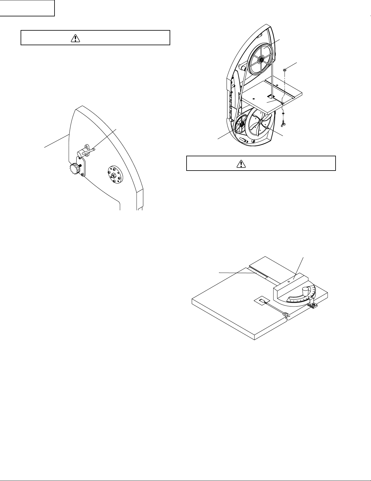
INSTALL CRANK HANDLE (Fig. A)
1. Line up slot on crank handle (1) with pin on the shaft (2).
2. Using mallet or piece of wood with regular hammer, drive
crank handle on the shaft until the pin on the shaft is
fully engaged in the slot.
INSTALL DUST COLLECTION BAG (Fig. B)
Dust collection system consists of a 30-micron bag and
clamp.
1. Place clamp (1) over bag sleeve (2).
2. Slide sleeve with clamp over dust port (3).
3. Secure in position by tightening clamp down. Do not
force handle. Rotate handle to increase clamp size.
INSTALL POINTER (Fig. C)
1. Squeeze the ends of the pointer (1) inward and carefully
insert each end into the holes located on the bracket of
the pointer assembly (2).
INSTALL WORKLIGHT BATTERY (Fig. D)
1. Press upward on worklight battery compartment cover (1)
to remove.
2. Install 9V battery (included) in compartment.
3. Replace cover.
WARNING
English
– 11 –
ASSEMBLY AND ADJUSTMENTS
Phillips Screwdriver Combination Square
Adjustable Wrench
Straight Edge
Feeler Gauge - size 0.02 Mallet
Fig. A
2
1
Fig. B
Fig. C
3
1
2
1
2
Fig. D
1
REMOVING BLADE (Fig. E, F)
Disconnect band saw from power source when changing or
adjusting blades. Wear leather gloves when handling band
saw blades. Never wear gloves when operating saw.
1. Turn blade tensioning lever (1) on the back of the tool
clockwise all the way until it locks in position to release
blade tension (see Figure E).
2. Release two latches (2) on the side of the tool and
open front door.
NOTE: When opening door, make sure latches are
completely free from tabs on frame and that angle scale
pointer is turned down away from door. Be careful to ensure
door does not contact table insert wing screw.
3. Remove table locking insert (Fig. F, 5) located in the front
of the table slot, take out the released blade and replace
with another blade.
INSTALLING BLADE (Fig. F)
1. Although most of the adjustments are not changed when
blade is removed, every adjustment should be checked
prior to using a newly installed blade.
2. Make sure blade teeth are pointing down towards table.
Turn blade inside out if necessary.
3. Slip new blade into table slot (1) and over the upper,
lower and idler blade wheels. Slide blade in between
blade guards.
4. Tension blade (see Figure E) by turning blade tensioning
lever (1) counterclockwise, as far as it will go. This is a
spring loaded, tensioning mechanism and it will
automatically apply required tension to the blade.
5. Close the front door and fasten latches.
NOTE: When closing door, make sure that the edges of the
door and frame are firmly fitted together before attempting
to secure door. This is necessary for proper operation of dust
collection system. The latches will not pull the door and frame
together.
6. Install table insert (5).
7. Track blade as described in the following sections.
To avoid injury, the blade tension, tracking, and upper and
lower guides and bearings must be properly adjusted before
operating the band saw. (See Adjustment Instructions, this
section)
MITER GAUGE (Fig. G)
A miter gauge (1) is supplied with your band saw to be used
in the table slot (2) on the right side of the blade. The miter
gauge can be tilted 0° to 60° right or left to maintain an
accurate angle for your workpiece.
WARNING
WARNING
English
– 12 –
Fig. E
1
2
Fig. F
2
5
4
1
3
Fig. G
1
2

To avoid injury, turn the switch OFF and unplug the band
saw from the power source before making any adjustments.
TILTING THE SAW (Fig. H)
The band saw body (1) tilts 0° to 45° left.
1. Loosen body lock handle (2) on rear of saw body.
2. Tilt the table to the desired angle on the scale (3) on
body using crank handle (4).
3. Tighten the lock handle.
BLADE TRACKING (Fig. I)
To avoid injury, turn the switch OFF and disconnect the saw
from the power source before making any adjustments.
Be very careful; improperly tracked blade may spring out
from wheels causing serious injury. Do not perform tracking
adjustment while band saw is running.
1. Open body door.
2. To check the blade tracking, rotate drive wheel by hand
in clockwise direction.
3. Proper tracking is achieved when drive and idler wheels
are aligned. Tracking plate (1) on the back of the tool
frame is used to tilt upper idler wheel and align all
three blade wheels.
4. Loosen up hex nut (2).
5. Loosen up socket head bolts (3). There are four socket
head bolts holding tracking plate. Bottom socket head
bolts should be loosened just enough to allow tilting of
the plate. If the bottom socket head bolt is loosened too
much, the plate will not tilt.
6. Using set screws, (4) tilt the plate in vertical (up and
down) plane until proper tracking is achieved. Upper idler
blade wheel tilts in the same direction as tracking plate.
• If blade rides away from cabinet, increase gap between
tracking plate and cabinet wall. If the blade rides into
cabinet, decrease the gap.
• When blade is tracking properly, tighten up hex nut and
all four socket head bolts.
• Properly tracked blade should ride at the center position
on all three wheels (drive and idlers).
UPPER BLADE GUIDE ASSEMBLY (Fig. J)
To avoid injury, turn the switch OFF and disconnect the saw
from the power source before making any adjustments.
NEVER make adjustments with the machine running.
1. Loosen the lock knob (1) and move the blade guide
assembly (2) up or down to 1/8″ above the workpiece.
2. Tighten the lock knob.
WARNING
WARNING
WARNING
English
– 13 –
Fig. H
2
4
1
3
Fig. I
1
4
Fig. J
1
2
2
3

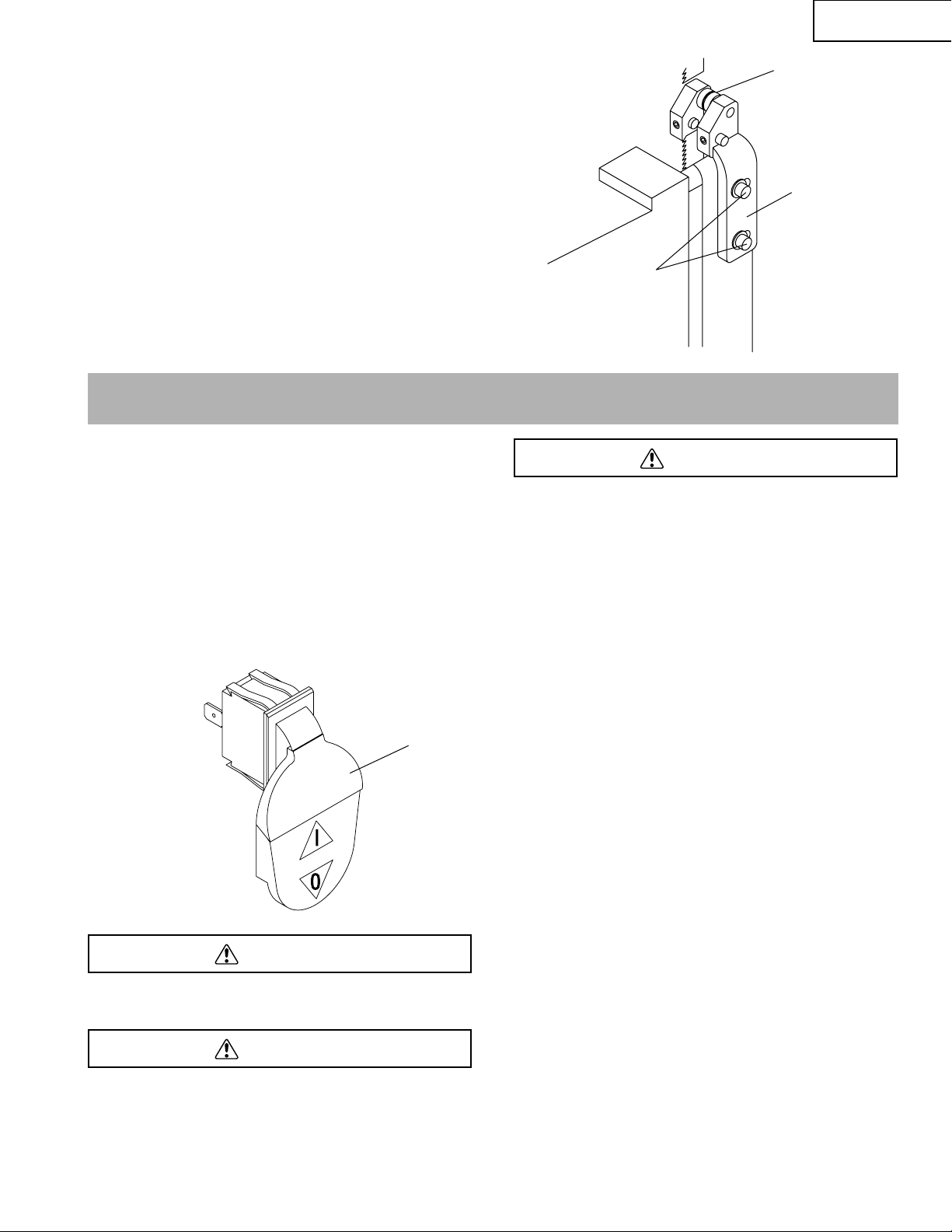
UPPER BLADE GUIDES AND BLADE SUPPORT BEARING
(Fig. K, L)
• The blade guard has been removed for clarity of
illustration. To avoid injury never operate the band
saw without all guards in place and in working order.
• To avoid injury, turn the switch OFF and disconnect
the saw from the power source before making any
adjustments. NEVER make adjustments with the
machine running.
NOTE: Make sure the blade is tensioned and tracking
properly. Adjust the blade guides and support bearing after
each blade tension and tracking adjustment. When the upper
blade guides and support bearings are adjusted, the lower
guides and bearings should also be adjusted.
Blade guides (Fig. K)
1. Make sure the blade is tensioned and tracking properly.
2. Loosen the front hex socket screws (1) with a hex
wrench.
3. Move the guides (2) as close to the blade (3) as possible
without pinching it.
4. Using a feeler gauge, make sure the space between
each guide and blade measures 0.02″ (the thickness of
a dollar bill).
5. Tighten the hex socket screws.
Support bearing (Fig. L)
6. Loosen the bearing hex nut (4).
7. Move the support bearing shaft (5) in or out, until the
bearing (6) is 1/64″ behind the blade.
8. Tighten the hex nut (4).
NOTE: The blade support bearing prevents the blade from
moving back too far and damaging the saw teeth setting.
LOWER BLADE GUIDES AND SUPPORT BEARING
(Fig. M, N)
To avoid injury, turn the switch OFF and disconnect the saw
from the power source before making any adjustments.
NEVER make adjustments with the machine running.
NOTE: Make sure the blade is tensioned and tracking
properly.
The lower blade guides and support bearings should always
be adjusted after the blade is tensioned, the tracking is
adjusted, and the upper blade guides and upper support
bearings are properly adjusted.
Blade guides (Fig. M)
1. Loosen both front hex socket screws (1) with a hex
wrench.
2. Move the guides (2) as close to the sides of the blade (3)
as possible without pinching it.
3. Using the feeler gauge, measure the spaces between
the guide and the blade. Adjust to 0.02″.
4. Tighten the hex screws.
WARNING
WARNING
English
– 14 –
Fig. K
1
2
3
Fig. L
6
6
Fig. M
1
3
2
3
5
4
2
Support bearing (Fig. N)
5. Loosen the socket head bolts (4) with the hex wrench.
6. Move the blade support (5) in or out until the blade is
positioned in groove of roller (6).
7. Tighten the socket head bolts.
English
– 15 –
Fig. N
6
5
4
BASIC SAW OPERATIONS
ON/OFF SWITCH (Fig. O)
The keyed switch is intended to prevent unauthorized use of
the band saw.
1. To turn the band saw ON (I) insert the yellow key (1) into
the key slot in the center of the switch.
2. Push the key firmly into the slot, then push switch to the
ON position to start the band saw.
3. To turn the band saw OFF (O) push the switch to the
down position.
4. Remove the yellow switch key, when the saw has come
to a complete stop, by gently pulling it outward.
Remove the switch key whenever the saw is not in use.
Place it in a safe place and out of reach of children.
ALWAYS lock the switch OFF when the saw is not in use.
Remove the key and keep it in a safe place. In the event of
power failure, blown fuse, or tripped circuit breaker, turn the
switch OFF and remove the key, preventing an accidental
startup when power comes on.
For your safety, read and understand all GENERAL and
SPECIFIC SAFETY INSTRUCTIONS on pages 4-5 before
using the band saw.
Operating band saws involves a certain amount of hazard.
Before attempting regular work, use scrap lumber to check
the settings and to get the feel of operating the band saw.
Read instructions and plan your work before cutting a
workpiece.
Do not turn the power ON until after you have made all
adjustments, checked that the guard is in place, and turned
the wheel by hand to make sure all parts work properly.
Always keep the guide assembly close to your work, 1/8″
above the workpiece.
Do not force the workpiece, against the blade. Light contact
permits easier cutting and prevents unwanted friction and
heating of the blade.
Sharp saw blades need little pressure for cutting. Steadily
move the workpiece against the blade without forcing it. To
avoid twisting the blade, do not turn sharp corners, saw
around corners.
A band saw is basically a “curve-cutting” saw. It is not capable
of doing intricate inside cutting as can be done with a scroll
saw.
It is also used for straight-line operations such as crosscutting,
ripping, mitering, beveling, compound cutting, and resawing.
WARNING
WARNING
WARNING
OPERATION
Fig. O
1

To avoid blade breakage, fire or other damage or injury,
NEVER use this band saw to cut ferrous metals.
CUTTING CURVES
When cutting curves, carefully turn the workpiece so the
blade follows without twisting. If the curve is so sharp that you
repeatedly back up and cut new kerf, use a narrower blade,
or a blade with more set (teeth further apart). When a blade
has more set, the workpiece turns easier but the cut is
rougher.
When changing a cut, do not withdraw the workpiece from
the blade. The blade may get drawn off the wheels.
To change a cut, turn the workpiece and saw out through the
scrap material area.
When cutting long curves, make relief cuts as you go along.
CIRCLE CUTTING (Fig. P)
1. Adjust the guide assembly to 1/8″ above the workpiece.
2. Use both hands while feeding the work into the blade.
Hold the workpiece firmly against the table. Use gentle
pressure. Do not force the work, ALLOW the blade
to cut.
3. The smallest diameter circle that can be cut is
determined by the width of the blade. For example, a
1/4″ wide blade will cut a minimum diameter of
approximately 1-1/2″.
BLADE SELECTION (Fig. Q)
CAUTION: Blade teeth are sharp. Use care when handling
a saw blade.
For longest wear and best cutting results, use the correct
blade thickness width, and temper for the type of material
you will cut.
When sawing small curves and delicate work, use narrow
blades. Otherwise, use the widest blade possible. For cutting
wood and similar materials with this band saw, purchase
blades in widths up to 3/8″, and a length of 63-1/2″.
Do not cut ferrous metals with this band saw.
Common causes of blade breakage:
• Poor guide alignment and adjusting.
• Forcing or twisting a wide blade around a short radius.
• Feeding too fast.
• Dull teeth or not enough set.
• Too much blade tension.
• Setting top guide assembly too high above the workpiece.
• Lumpy or improperly finished braze or weld on the blade.
• Continuous running of blade when not cutting.
Fig. Q
To avoid possible injury or damage, NEVER use this band
saw to cut ferrous metals.
CAUTION: When cutting nonferrous metals, metal shavings
can react with wood dust and start a fire. To avoid this:
1. Disconnect any dust collection bag from the
band saw.
2. Remove all traces of wood dust from inside the saw.
3. Remove all metal shavings from inside the saw
before sawing wood again.
WARNING
Operation Recommended Blade Width (Inches)
Cross Cutting 1/4, 3/8
Mitering 1/4, 3/8
Beveling 1/4, 3/8
Compound Cutting 1/4, 3/8
Circle Cutting See Fig. P
Curve Cutting 1/8, 1/4
WARNING
English
– 16 –
Fig. P
1/2″D1″D 1-1/2″D2″D 2-1/2″D
1/8″ 3/16″ 1/4″ 3/8″ 1/2″
Minimum
Circle Diameter
Blade Width

English
– 17 –
GENERAL MAINTENANCE
• For your own safety, turn switch OFF and remove the
plug from power source receptacle before maintaining,
cleaning, adjusting, or lubricating your band saw.
• To avoid fire or toxic reaction, never use gasoline,
naphtha, acetone, lacquer thinner or similar highly
volatile solvents to clean the band saw.
• To avoid eye injury from blowing debris, wear safety
goggles when blowing out sawdust.
BAND SAW
Sawdust will accumulate under the table and base. This could
cause difficulty in the movement of the body when setting up
a band saw cut, and also cause a fire hazard.
Frequently blow out or vacuum up the sawdust.
Keep your band saw clean. Remove the sawdust from the
inside. Vacuum or blow out frequently.
Do not allow filth to build up on the table, the guides, or the
support bearings. Clean them with gum and pitch remover.
NOTE: Do not immerse the support bearing in the gum and
pitch remover.
Put a thin coat of paste wax on the table so that the wood
slides easily while cutting.
BLADE WHEEL TIRES
Pitch and sawdust that build up on the tires, should be
removed with a stiff brush or scraped off with a piece of
wood.
NOTE: To avoid damaging the tires, do not use a sharp knife
or any kind of solvent.
When the tires become worn they should be replaced. When
replacing the tires, stretch them around the wheels but do
not glue them on.
MOTOR
Frequently blow or vacuum out any sawdust from the motor.
To avoid electrocution or fire, immediately replace a worn,
cut or damaged power cord.
LUBRICATION
All of the bearings are packed with grease at the factory.
They require no further lubrication.
BATTERIES
Check the batteries regularly to avoid deterioration. Remove
the batteries if you will not be using the worklight for an
extended time.
CAUTION: Never put lubricants on the blade while it is
spinning.
WARNING
WARNING
MAINTENANCE

• To avoid injury from an accidental start, turn the switch OFF and remove the plug from the power source before making
any adjustments.
• All electrical or mechanical repairs should be done only by qualified service technicians. Contact Hitachi Authorized
Service Center.
GENERAL
English
– 18 –
TROUBLESHOOTING GUIDE
PROBABLE CAUSE
1. Not tracking properly.
2. Defective blade.
1. Blade too loose.
2. Cutting too small a radius.
3. Dull blade.
4. Overloading motor.
1. Too much tension on the blade.
2. Kink in the blade caused by cutting too
small a radius or turning the material
too fast when cutting.
3. Cutting incorrect material.
1. Work not square.
2. Rate of feed too great.
3. Blade guides not adjusted properly.
4. Upper blade guide too far from
workpiece.
5. Dull blade.
6. Blade guide assembly loose or
blade thrust bearing loose.
1. Too much feed.
2. Blade too coarse.
1. Dust collection bag full.
2. Impeller loose or broken.
PROBLEM
Blade does not run in the
center of the upper wheel.
Band saw slows down
when cutting.
Blades braking.
Crooked cuts.
Rough cuts.
Dust collection not working.
REMEDY
1. Adjust tracking. See ASSEMBLY AND
ADJUSTMENTS section BLADE TRACKING.
2. Replace blade.
1. Adjust blade tension. See SCHEMATIC A,
page 56. Adjust TENSION ROD, Ref. 0053,
clockwise to increase tension; counterclockwise
to decrease tension.
2. Stop feeding, back up the material slightly,
until the band saw speeds up.
3. Replace blade.
4. Slow down, trying to cut too fast. See MOTOR
TROUBLESHOOTING GUIDE on page 19.
1. Adjust blade tension. See SCHEMATIC A,
page 56. Adjust TENSION ROD, Ref. 0053,
clockwise to increase tension; counterclockwise
to decrease tension.
2. Use correct cutting technique. See OPERATION
section GENERAL CUTTING.
3. See OPERATION section BLADE SELECTION.
1. Use miter gauge; adjust tilt of head at 90°.
2. Reduce rate of feed.
3. Move both guide blocks within .002″ from blade
(use gauge).
4. Adjust upper guide to just clear workpiece by 1/8″.
5. Replace blade.
6. Tighten blade thrust bearing within 1/64″
behind blade back.
1. Reduce feed.
2. Replace with finer blade.
1. Empty dust collection bag.
2. Replace impeller.
WARNING
 Loading...