


(15” model) |
(20” model) |
Caution
Be sure to read this manual before servicing. To assure safety from fire, electric shock, injury, harmful radiation and materials, various measures are provided in this Hitachi liquid crystal television/monitor.
Be sure to read the cautionary items described in the manual to maintain safety before servicing.
Service Warning
1.The LCD Panel Module is made of glass. When handling broken LCD Panel Module, take special care not to be injured.
2.Replacement work should only start after the LCD Panel Module and the AC/DC Power Supply has become sufficiently cool.
3.Take special care of the LCD display panel and do not damage its surface.
4.Do not touch the LCD Panel Module with your bare hands and protect its surface from stains.
5.It is recommended to use clean soft gloves during servicing in order to protect the LCD display panel and the service personnel himself.
Contents
* |
SAFETY NOTICE................................................... |
2 |
* |
DISPLAY MODES.................................................. |
2 |
* |
SPECIFICATIONS................................................... |
3 |
* |
LOCATION OF CONTROLS...................................... |
4 |
* |
CONNECTIONS...................................................... |
7 |
* |
FACTORY SETTTINGS........................................... |
10 |
* |
TROUBLESHOOTING.............................................. |
11 |
* |
SCHEMATIC DIAGRAMS............................................. |
12 |
* |
PRINTED CIRCUIT BOARD........................................ |
21 |
* |
BLOCK DIAGRAM............................................... |
27 |
* |
WIRING DIAGRAM............................................. |
28 |
* EXPLODED VIEW & MECHANICAL PARTS LIST.......... |
29 |
|
* |
INFORMATION OF ICS............................................... |
31 |
SPECIFICATIONS AND PARTS ARE SUBJECT TO CHANGE FOR IMPROVEMENT
Liquid Crystal Display Television/Monitor
July 2005 |
Digital Media Systems Group, Hitachi Asia Ltd. |
Downloaded From TV-Manual.com Manuals

SAFETY NOTICE
Maintenance and repair of this LCD TV/monitor should be done by qualified service personnel only.
Critical parts that have special safety characteristics are identified by a 
 in the replacement parts list. Use of any substitute replacement part that does not have the same safety characteristics as the recommended replacement part in the parts list might create shock, fire and / or other hazards.
Read and comply with all caution and safety related notes on or inside the LCD/monitor cabinet, the printed circuit boards or the LCD Panel Module. Please note the following safety symbols indicated below.
CAUTION
RISK OF ELECTRIC SHOCK DO NOT OPEN
TO REDUCE THE RISK OF ELECTRIC SHOCK, DO NOT REMOVE COVER.
NO USER-SERVICEABLE PARTS INSIDE. REFER SERVICING TO QUALIFIED SERVICE PERSONNEL.
This symbol indicates “dangerous voltage” inside the product that presents a risk of electric shock or personal injury.
This symbol indicates important instructions accompanying the product.
DISPLAY MODES
|
15” Incoming display mode (input) |
|
||
Resolution |
Horizontal |
Vertical |
Pixel Frequency |
Comment |
Frequency (KHz) |
Frequency (Hz) |
(MHz) |
||
640 x 480 |
31.47 (N) |
60.00 (N) |
25.18 |
DOS |
800 x 600 |
37.88 (P) |
60.32 (P) |
40.00 |
VESA |
1024 x 768 |
48.36 (N) |
60.00 (N) |
65.00 |
VESA |
|
20” Incoming display mode (input) |
|
||
Resolution |
Horizontal |
Vertical |
Pixel Frequency |
Comment |
Frequency (KHz) |
Frequency (Hz) |
(MHz) |
||
640 x 480 |
31.47 (N) |
60.00 (N) |
25.18 |
DOS |
800 x 600 |
37.88 (P) |
60.32 (P) |
40.00 |
VESA |
*Modes, which are not listed in the above table, may not be supported. For an optimal picture it is recommended to choose a mode listed in the table.
*For 15”model, there are 3 types of incoming display modes compatible with Windows as shown in the tables above.
*For 20”model, there are 2 types of incoming display modes compatible with Windows as shown in the table above.
*Sometimes, the image may be disrupted due to the frequency standard from the VGA card. However, this is not an error. You may improve this situation by activating the automatic adjustment or by manually changing the phase and the clock settings in the menu.
*If you switch off the TV/monitor, interference lines may occur on your screen. Please note that this is normal.
*To extend the service life of the product, we recommend that you use your computer’s power management function.
- 2 -
Downloaded From TV-Manual.com Manuals
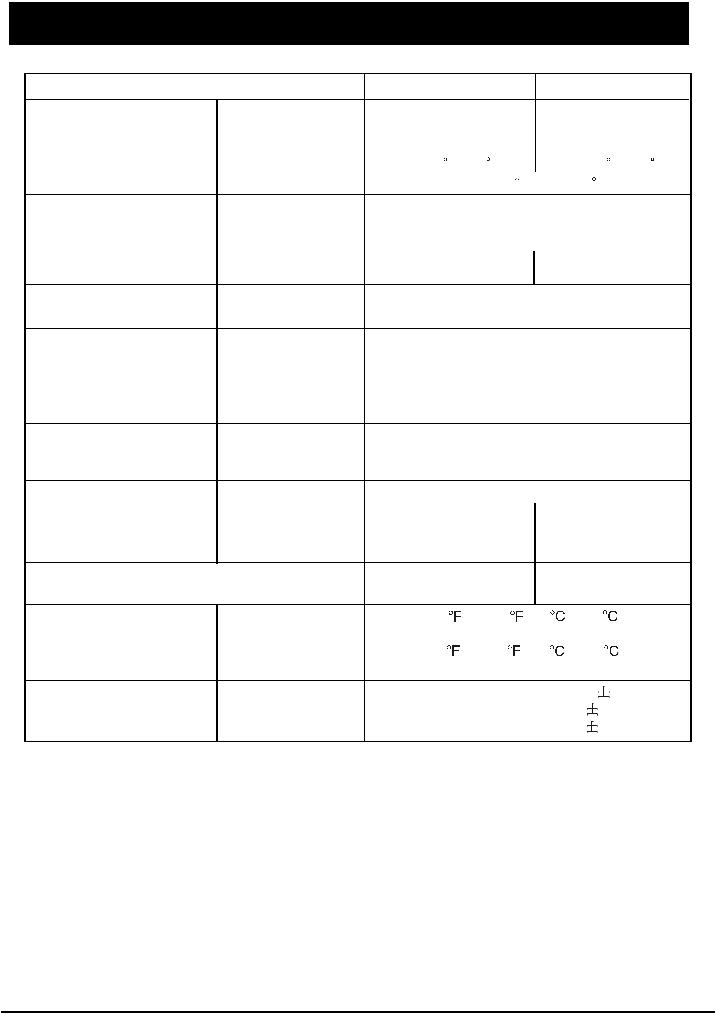
SPECIFICATIONS
Model |
|
C15-LC880SNT |
C20-LC880SNT |
Panel |
Size |
15.1” |
20.1” |
|
Display Size |
304.1(H) X 228.1(V)mm |
408(H) X 306(V)mm |
|
Pixel Pitch |
0.297(H) X 0.297(V)mm |
0.51(H) X 0.51(V)mm |
|
Viewing Angle (H/V) |
<140 / 125 |
<160 / 140 |
|
Screen Tilt Angle |
Front 5 / Rear 15 |
|
Frequency |
Horizontal |
30 ~ 70KHz |
|
|
Vertical |
50 ~ 75Hz |
|
|
Contrast Ratio |
400:1 |
|
|
Brightness |
400 cd/m2 |
500 cd/m2 |
|
Display Color |
16.2Million |
16.7Million |
Display Resolution |
Optimum Mode |
1024 X 768 @ 70Hz |
800 X 600 @ 70Hz |
|
Maximum Mode |
1024 X 768 @ 75Hz |
800 X 600 @ 75Hz |
Input Signal |
Sync. |
H/V Separate, TTL, P. or N. |
||||||||||
|
|
H/V Composite, TTL, P. or N. |
||||||||||
|
|
Sync-on-green 0.3 Vp-p, N. |
||||||||||
|
Video Signal |
|
1 Vp-p @ 75 ohm |
|
|
|
|
|
||||
|
RGB Signal |
|
0.7Vp-p @ 75 ohm |
|
|
|
|
|
||||
TV / Video |
Color System |
|
PAL / SECAM / NTSC |
|
||||||||
|
Sound System |
|
DK / I / BG / M |
|
|
|
|
|
||||
|
Video Format |
CVBS, S-VIDEO, Y/Pb/Pr |
|
|||||||||
Power Supply |
Input |
AC 100 - 240Vrms (50Hz / 60Hz) |
||||||||||
|
Output (Adapter) |
DC 12V / 4.5A |
|
DC 12V / 5.2A |
||||||||
Power Consumption |
Typical |
<54W |
|
|
|
|
<65W |
|||||
|
Power Saving |
<3W |
|
|
|
|
<3W |
|||||
Dimensions (WxHxD) |
|
390 X 401 X 188mm |
552 X 460 X 188mm |
|||||||||
Weight |
|
5.3Kg |
|
|
|
|
8.4Kg |
|||||
Environmental Considerations |
Operating Temperature |
50 |
to 104 |
(10 |
to 40 |
) |
||||||
|
Operatiing Humidity |
|
10% to 80% |
|
|
|
|
|
||||
|
Storage Temperature |
13 |
to 113 |
(-25 |
to 45 |
) |
||||||
|
Storage Humidity |
|
5% to 95% |
|
|
|
|
|
|
|
|
|
Audio Characteristics |
AudioInput |
RCA Jack Red(R) White(L), 0.5 |
|
|
|
0.3Vrms |
||||||
|
|
|
||||||||||
|
|
|
||||||||||
|
Frequency |
RF: 100Hz ~ 12KHz (at |
|
|
3dB) |
|||||||
|
|
|
||||||||||
|
|
|
||||||||||
|
Response |
AV : 100Hz ~ 13KHz (at |
|
|
3dB) |
|||||||
|
|
|
|
|||||||||
|
|
|
|
|||||||||
Note:
*Design and specifications are subject to change without notice.
*Weight and dimensions shown are approximate values only.
- 3 -
Downloaded From TV-Manual.com Manuals
LOCATION OF CONTROL (Continued) |
|
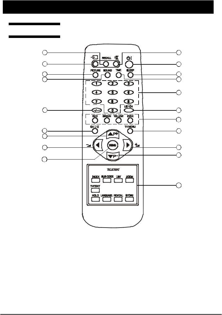
LOCATION OF CONTROL |
|
Remote Control |
|
1 |
2 |
3 |
4 |
5 |
6 |
7 |
8 |
|
9 |
10 |
11 |
|
12 |
13 |
14 |
15 |
|
16 |
16 |
17 |
15 |
|
|
|
12 |
1.RECALL button
To display setup information of channel
2.MUTE button
To switch on/off sound mute
3.TV/VIDEO button
To select TV, AV1, AV2, S-Video, COMP, VGA or DVI mode
4.STANDBY button
To switch on the LCD TV/monitor when at standby mode or vice versa
5.PICTURE button
To select picture effect mode (Standard/Soft/Custom/Bright)
6.SLEEP button
To on/off sleep mode and set the sleep timer
- 4 -
Downloaded From TV-Manual.com Manuals

LOCATION OF CONTROL
7.SOUND button
To select the sound effect mode (Custom/News/Cinema/MusicHall)
8.TIME button
To display the preset time
9.NUMBER buttons
To directly select program number
10.DIGIT button
To select one, two or three-digit program number input options
11.LST-CH button
To return to previously selected program number
12.TELETEXT buttons (OPTIONAL)
These buttons are used for certain models with Teletext functions only. For further details, refer to the “TELETEXT FUNCTION” section in this manual
13.CH I/II button
To switch between NICAM / A2 stereo and mono sound output
14.TV MENU button
To enter the TV menu directly to tune the programs
15.P-/+ (
 ) buttons
To select previous / next program and to operate the menu
16. -/+ (
-/+ (

 ) buttons
To decrease / increase volume and to adjust the menu
17.MENU button
To enter or exit from the MENU (TV/AV mode) To accept your selection (PC mode)
- 5 -
Downloaded From TV-Manual.com Manuals
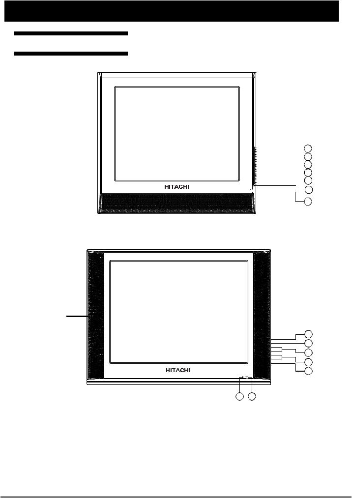
LOCATION OF CONTROL
Front and Side Panels
For 15” model 
 1
1 
 2
2

 3
3

 4
4 
 5
5

 6
6
7
For 20” model |
1 |
2 |
3 |
4 |
5 |
6 7
1. |
TV/VIDEO button |
5. |
STANDBY button |
|
To select TV, AV1, AV2, S-Video, |
|
To switch on when at standby mode or vice |
|
COMP, VGA or DVI mode |
|
versa |
2. |
MENU button |
6. |
POWER INDICATOR |
|
To enter or exit from the menu |
|
Lights up in red when the set is on standby; |
3. |
PROGRAM buttons |
|
Lights up in green when the set is power on |
|
To select previous/next program |
7. |
REMOTE CONTROL SENSOR |
4 . VOLUME buttons |
|
Infrared sensor for the remote control |
|
|
To decrease/increase volume |
|
|
- 6 -
Downloaded From TV-Manual.com Manuals
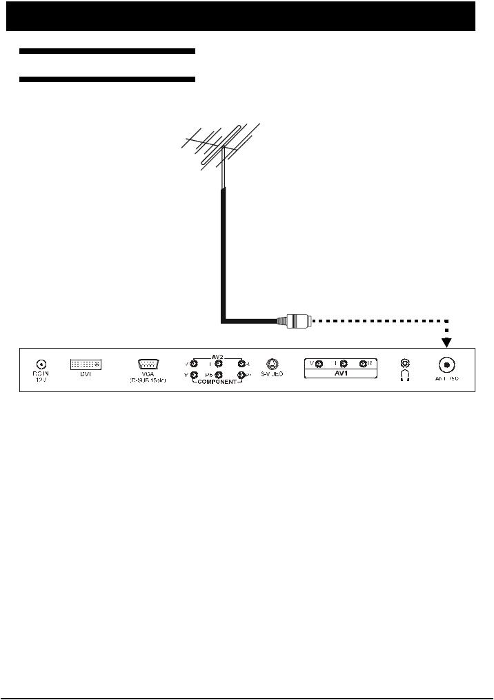
CONNECTIONS
Connecting The Antenna
Antenna
Note:
*Aerial connections: Standard-phono socket 75 or F connector.
*Input impedance: 75 unbalanced.
*For Australia only -Install an external aerial conforming to AS 1417.1 for safety purpose.
- 7 -
Downloaded From TV-Manual.com Manuals
CONNECTIONS
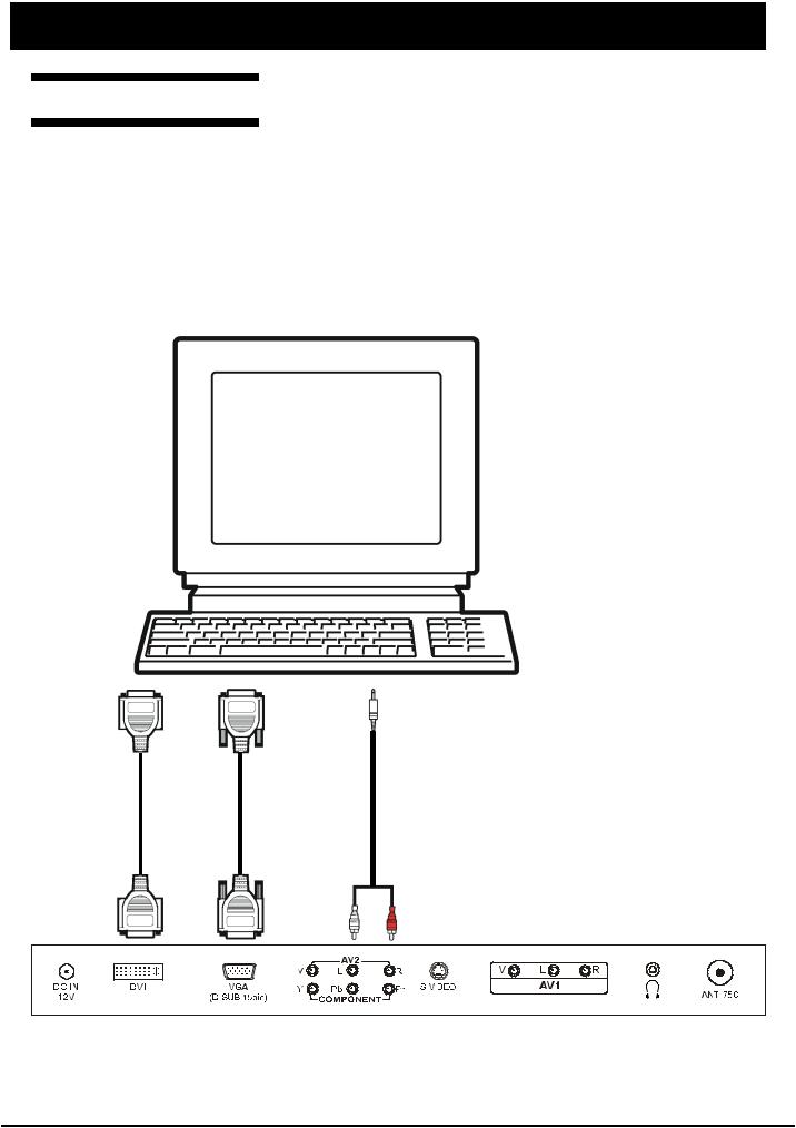
Connecting The PC
STEPS:
1.Switch off all power supplies to the equipment and TV set before connection
2.Connect the signal and audio cables from the computer output terminal to the TV
3.Connect power cord
4.Switch on the TV first, then switch on the computer
5.If the TV still does not function properly, please refer to the troubleshooting section to diagnose the problem.
*Please do not open the cover of the TV
oT
VD
Io tp u
tu
oT
VD i I pn tu
(D -us )b
(D -us )b
oT
ig S lan
tuo tup
oT
ig S lan
ipn tu
oT
duA io
tuo tup
oT(A
duA)2V io
ipn tu
Note:
Do not pull the cables. When connecting and disconnecting the cables, do it with your hand holding the connector.
- 8 -
Downloaded From TV-Manual.com Manuals
CONNECTIONS
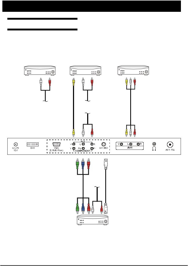
Connecting AV Equipment
This TV set provides AV1, AV2 input terminals, S-Video and a group of Y/Pb/Pr terminal for connection to VCR, VCD, DVD or other’ video equipment.
Please refer to the instruction manual of the other equipment for more information on the connection to the TV.
VIDEO EQUIPMENT |
VIDEO EQUIPMENT |
VIDEO EQUIPMENT |
||||||
|
|
|
|
|
|
|
|
|
|
|
|
|
|
|
|
|
|
|
|
|
|
|
|
|
|
|
|
|
|
|
|
|
|
|
|
oT
uA io d
uo tp tu
To Audio input (AV2)
To |
To |
Vdei |
Audi |
oou put t |
oou put t |
|
To Audio |
|
input (AV2) |
ToV dei oi |
AV( ToA 2) ud oi |
nput |
npi u |
|
t |
ni To p |
|
ni To p |
ut C |
|
ut S |
omp on |
|
Vd-i eo |
ent |
To Audio |
|
|
||
|
input (AV2) |
|
ou To put Co t m pon en |
|
ou To put S- t V dei o |
t |
|
|
|
|
|
|
|
|
|
|
|
VIDEO EQUIPMENT
oTuA
Vd iio edo ou
atp dntu
oTuA Vd i io d
ein op
ta
ndu
Note:
*Please disconnect all the power supplies to the equipment and TV set before connection.
*Do not pull the cables. When connecting and disconnecting the cables, do it with your hand holding the connector.
*Only 1 set of audio cable is to be connected to Audio input terminals of AV2.
- 9 -
Downloaded From TV-Manual.com Manuals

FACTORY SETTINGS
1.Press MENU button, then press 3210 using the number button on the remote control to enter into the factory setting.
2.The factory setting menu will be displayed on the screen. The following table is shown when in AV mode:
Item |
Factory setting |
C15-LC880SNT |
|
C20-LC880SNT |
1 |
Basic Setting |
Backlight |
50 |
|
|
|
NVRAM Addr |
|
|
|
|
NVRAM Val |
|
|
2 |
Color Setting |
Auto Adjust |
|
|
|
|
Red |
|
0 |
|
|
Green |
|
0 |
|
|
Blue |
|
0 |
|
|
Red Offset |
0 |
|
|
|
Green Offset |
0 |
|
|
|
Blue Offset |
0 |
|
|
|
Min Volume |
0 |
|
|
|
Max Volume |
68 |
|
3 |
Sound Setting |
Dot1 X |
Pos |
31 |
|
|
Dot1 Y |
Pos |
69 |
|
|
Dot2 X |
Pos |
62 |
|
|
Dot2 Y |
Pos |
81 |
4 |
4200K 5000K Warm |
Brightness |
128 |
|
|
|
Contrast |
128 |
|
|
|
Red |
|
247 |
|
|
Green |
|
237 |
|
|
Blue |
|
237 |
5 |
STANDARD |
Brightness |
128 |
|
|
|
Contrast |
128 |
|
|
|
Red |
|
255 |
|
|
Green |
|
255 |
|
|
Blue |
|
255 |
6 |
COOL |
Brightness |
128 |
|
|
|
Contrast |
126 |
|
|
|
Red |
|
224 |
|
|
Green |
|
228 |
|
|
Blue |
|
251 |
7 |
CUSTOM |
Brightness |
128 |
|
|
|
Contrast |
128 |
|
|
|
Red |
|
255 |
|
|
Green |
|
255 |
|
|
Blue |
|
255 |
8 |
Advanced Setting |
Factory Mode |
1 |
|
|
|
Power Mode |
1 |
|
|
|
Panel Index |
34 |
|
|
|
Decder SatHue |
0 |
|
|
|
Enable Zoom |
1 |
|
|
|
Enable SCART P 1 1 |
||
|
|
Enable DVI Port |
1 |
|
|
|
Factory Reset |
|
|
9 |
Version Info |
V1.9-C15-LC880SNT |
|
V1.9-C20-LC880SNT |
|
|
ADDC:V8-L15GC1-A1D01 |
ADDC:V8-L20GC1-A1D01 |
|
|
|
DDDC:V8-L15GC1-A1D02 |
DDDC:V8-L20GC1-A1D02 |
|
- 10 -
Downloaded From TV-Manual.com Manuals
TROUBLESHOOTING
TV DOES NOT TURN ON
Is the power cord and DC adapter plugged in?
Yes
LED lights up
Yes
Press Power button
No  Plug in
No |
Check LED |
Normal |
|
|
|
|
Defective |
|
|
Replace LED |
|
|
with a new one |
|
LED light is green LED light is red
Check inverter PWB unit Check MCU(U4)
|
Normal |
Defective |
|
1. |
Check MCU (U4) |
1. |
Connect the line |
2. |
Check CN3 (or |
||
|
CN7) is connected |
|
of J9 and inverter |
3. |
Check U8 has |
2. |
Replace inverter |
|
VCC voltage |
|
with a new one |
Defective
1.Replace MCU with a new one.
2.Replace U8 with a new one.
Defective |
Normal |
|
Replace MCU with |
Replace DRIVE |
|
PWB unit with |
||
a new one |
||
a new one |
||
|
Check power input system
1.AC adapter
*Normal?
*Connected properly?
2.U9 has +5V?
3.U10 has 3.3V?
4.LED controls electrocircuit?
5.JD3 and JD2 are connected?
- 11 -
Downloaded From TV-Manual.com Manuals

SCHEMATIC DIAGRAMS
Main Diagram-1
- 12 -
Downloaded From TV-Manual.com Manuals
 Loading...