


C29-TF641S

…
…
…
…
…
…
HITACHI
HITACHI
HCPT
C29-TF641S/SN/ST/SNT
C29-TF651S/SN/ST/SNT
T1-003
SERVICE MANUAL
C29-TF751S/SN/ST/SNT
T1 Chassis
CAUTION :
CONTENTS
SAFETY PRECAUTIONS ...………………...…………….……………………………………………
PRODUCT SAFETY NOTICE …………...…………….………...……………...…………….………
REMOTE CONTROL UNIT ……………..………...…………….……………………………………
GENERAL OPERATIONS GUIDE .………………...…………….……………………………………
Before servicing this chassis, it is important that the service techician reads the " Safety Precaution "
and " Product Safety Notices " in this Service Manual.
2
2
3
4
CIRCUIT DESCRIPTION …………...…………….……………………………………………………
ADJUSTMENT INSTRUCTIONS ……………………...…………….…………………………………
REPLACEMENT PARTS LIST …………………...…………….………………………………………
SPECIFICATIONS AND PARTS ARE SUBJECT TO CHANGE FOR IMPROVEMENT.
COLOR TELEVISION
5
6
12
MARCH 2005 Hitachi Consumer Products ( THAILAND ) , Ltd.

SAFTY PRECAUTIONS
WARNING: The following precautions should be
opserved.
1. Do not install , remove, or handle the picture tube in could produce X-radiation moderately in excess of de any manner unless shatter proof goggles are worn. sign levels. The high voltage must not, under any cir People not so equipped should be kept away while cumstances, exceed 34kV on the chassis.
picture tubes are handled. Keep picture tube away
from the body while handing.
2. When service is required, an isolation transformer receiver is the picture tube. The tube utilized for the
should be inserted between power line and the above mentioned function in this chassis is specially
receiver before any service is performed on the constructed to limit X - radiatuion.
chassis. For continued X-radiation protection, replace tube with
3. When replacing the chassis in the cabinet,ensure
all the protective devices are put back in place,such
as barriers, non - metallic knobs, adjustment or
compartment covers or shields, isolation resistors/ Many electrical and mechanical parts in HITACHI
capacitors, etc. television receiver have special safety related
4. When service is required, observe the original lead evident from visual inspection, nor can be protection
dressing. Extra precaution should be taken to afforded by them necessarily be obtained by using
assure correct lead dressing in the high voltage
circuitry area. Particularly note the R. G. B. lead wattage, etc. Replacement parts which have these
dressing. Ensure they are dressed well away from special safety characteristics are identified by marking
the horizontal scan and F.B.T. circuitry. with a on the schematics and replacement
5. Always use the manufacturer ' s replacement
component. Always replace original spacers and safety characteristics as the HITACHI recommended
maintain lead lengths. Especially critical components replacement one, shown in the parts list in this Service
are indicated thus on the parts list and Manual, may create electrical shock, fire, X - radiation,
should not be replaced by other makes.
Furthermore, where a short circuit has occurred,
replace those components that indicate evidence of Product Safety is continuously under review and new
overheating. instructions are issued from time to time. For the latest
6. Before returning a serviced receiver to the customer, Manual. A subscription to ,or additional copies of
the service technician must thoroughly test the unit HITACHI Service Manuals may be obtained at a nominal
to be certain that it is completely safe to operate charge from your HITACHI sales offices.
without danger of electrical shock, and be sure that
no protective device built into the instrucment by the
manufacturer has became defective, or inadvertenly The line output stage can develop voltages in excess
damaged during servicing. Therefore, the following of 25 kV; if the E.H.T cap is required to be removed,
checks are recommended for the continued discharge the anode cap to chassis via a high value
protection of the customers and service techninians. resistor, prior to its removal from the tube.
HIGH VOLTAGE
High voltage should always be kept at the rated value
of the chassis and no higher. Operating at higher
voltages may cause a failure of the picture tube or high
voltage supply, and also, under certain circumstances
X-RADIATION
TUBES : The primary source of X - radiation in this
the same type as the original, HITACHI approved type.
PRODUCT SAFETY NOTICE
characteristics. These characteristics are often not
replacement components rated for higher voltage,
parts list in this Service Manual.The use of a substitute
replacement component which does not have the same
or other hazards.
information,always consult the current HITACHI Service
TUBE DISCHARGE
INSULATION
Insulation resistantce should not be less than 4.5 Mohm
at 500 VDC between the mains poles and any accessible
metal parts. Also, no flashover or breakdown should
occur during the dielectric strength test, applying 3.2kV
AC for two seconds between the main poles and
accessible metal parts.
- 2 -
R
REMOTE CONTROL UNIT
19
16
10
11
2
1
6
7
5
17
18
14
4
8
9
12
3
15
13
19
16
20
10
11
2
1
6
7
5
17
18
14
4
9
8
12
3
15
13
Models without Teletext Models with Teletext
POWER ON/OFF SWITCH DEFAULT
1. 11.
2. 12.
INPUT SELECTOR MUTE
3. 13.
VOLUME UP/DOWN CHI/II (FOR NICAM/A2 MODELS)
4. 14.
PROGRAMME UP/DOWN PROGRAMME SELECTOR (DIRECT KEY)
5. 15.
RECALL CURSO
6. 16.
SURROUND SOUND RETURN
7. 17.
MENU COLOR SYSTEM
8. 18.
TIMER SOUND SYSTEM
9. 19.
PICTURE EQUALIZER
10. 20
SOUND T/TEXT FUNCTION KEY (T/TEXT MODELS ONLY)
- 3 -

GENERAL OPERATIONS GUIDE
With this set, all adjustments/settings are performed by selecting from menu screens. Different menu screens and details
of adjustments/settings are shown below. To access the menu screen, press the button, then select the item by
pressing the up/down cursor buttons and adjust by the left/right cursor buttons .
MENU
- 4 -

- 5 -
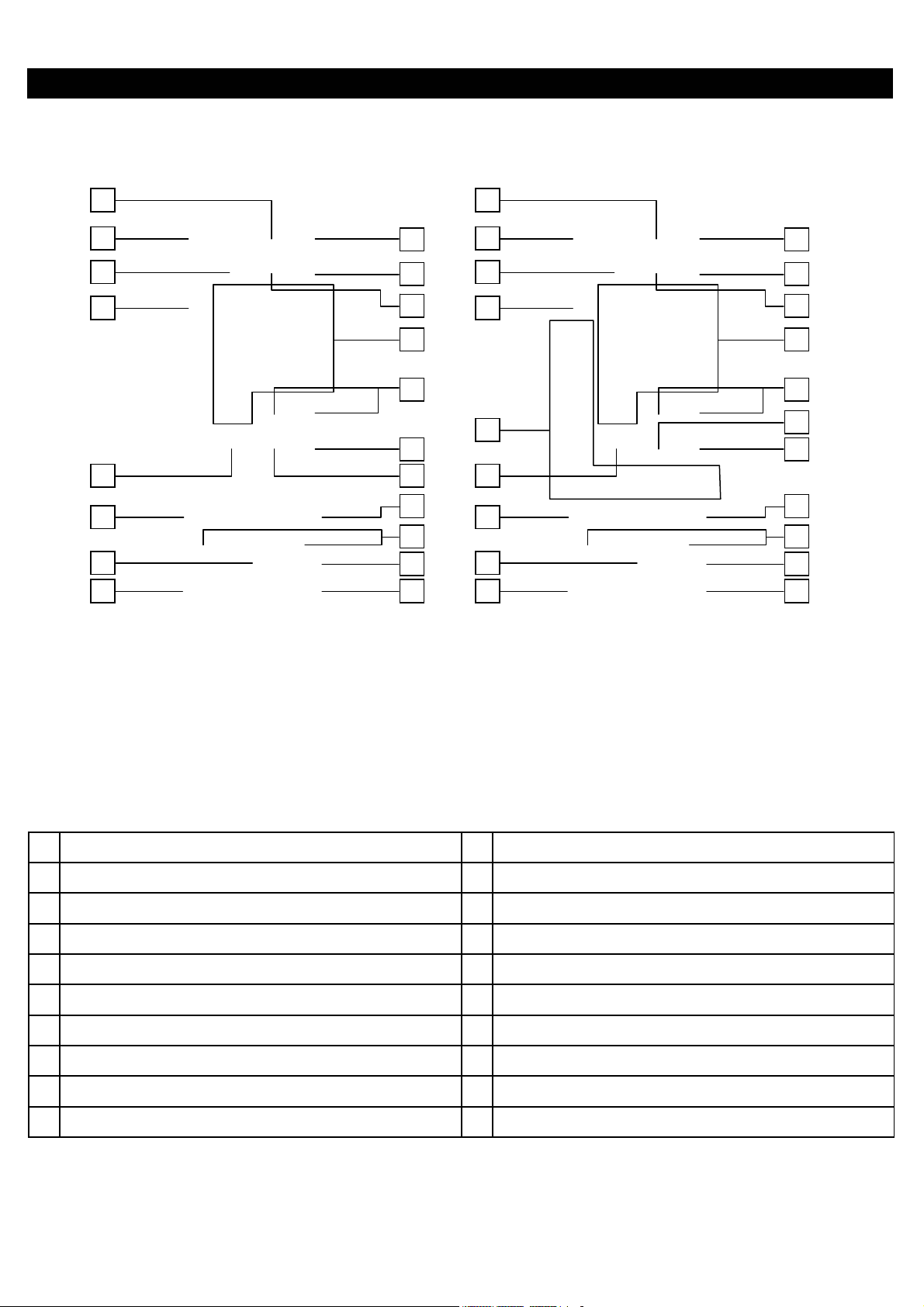
BLOCK DIAGRAM
A
A
DJUSTMENT INSTRUCTIONS
HOW TO GO TO SERVICE MODE
1. How to go to adjustment mode no 001 ~ 022
Procedure
(1) Turn TV off by power switch on the TV set.
(2) Press " FUNCTION " button on the TV set and kept depress the button.
(3) Turn TV on by power switch on the TV set.
2. How to go to adjustment mode no 101 ~ 328
Procedure
(1) Set volume to be “0”.
(2) Press button on remote control to go to standby mode.
(3) Press “TV/VIDEO” button on the TV set, and kept depress the button.
(4) Press button on remote control to go to operation mode.
(5) TV will show service table,then please cancel to keep depress the "TV/VIDEO" button.
Note : 1. Press the UP/DOWN cursor buttons
2. Adjust data by the left/right cursor buttons .
3. Press "RECALL" buttons to restore the data.
+B ADJUSTMENT
PREPARATION PROCEDURES
1
AC input voltage 230 +
2 Turns on the set and set the brightness and contrast +B voltage : TP902
to Max.(Signal : Philips Pattern) GND : TP901
3 After 30 sec heat-run, check & adjust the +B voltage
FREE RUN FREQUENCY ADJUSTMENT
Receive a PAL-I monoscope signal on TV mode.
1
5V(50Hz)
PREPARATION PROCEDURES
to select adjustment mode no.
1
1
djust R954 to obtain +B voltage as below
Select adjustment mode no. 1 and press "MENU" button
one time.
VIF-VCO FREE RUN FREQUENCY ADJUSTMENT
PREPARATION PROCEDURES
Receive a PAL-I monoscope signal on TV mode.
1
Select adjustment mode no. 2 and press "MENU" button
1
one time.
- 6 -
SOUND TRAP FREQUENCY ADJUSTMENT
A
PREPARATION PROCEDURES
Receive a PAL-I monoscope signal on TV mode.
1
Select adjustment mode no. 3 and press "MENU" button
1
one time.
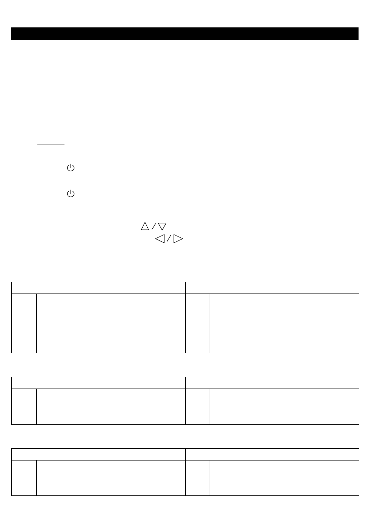
SECAM R-Y OFFSET ADJUSTMENT
PREPARATION PROCEDURES
1 Receive a secam color bar signal on Video 2. 1 Select adjustment mode no. 4.
2 Connect oscilloscope probe to pin 5 of E701. 2 Adjust output level at pin 5 of E701 as indicated below
using service mode no. 4.
0.1 V
0 +
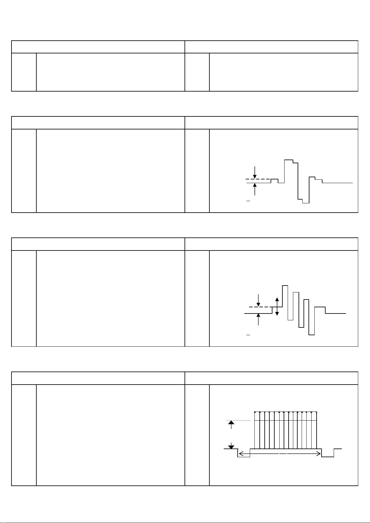
SECAM B-Y OFFSET ADJUSTMENT
PREPARATION
1 Receive a secam color bar signal on Video 2. 1
2 Connect oscilloscope probe to pin 5 of E701. 2
Select adjustment mode no. 5.
djust output level at pin 5 of E701 as indicated below
PROCEDURES
using service mode no. 5.
0.1 V
0 +
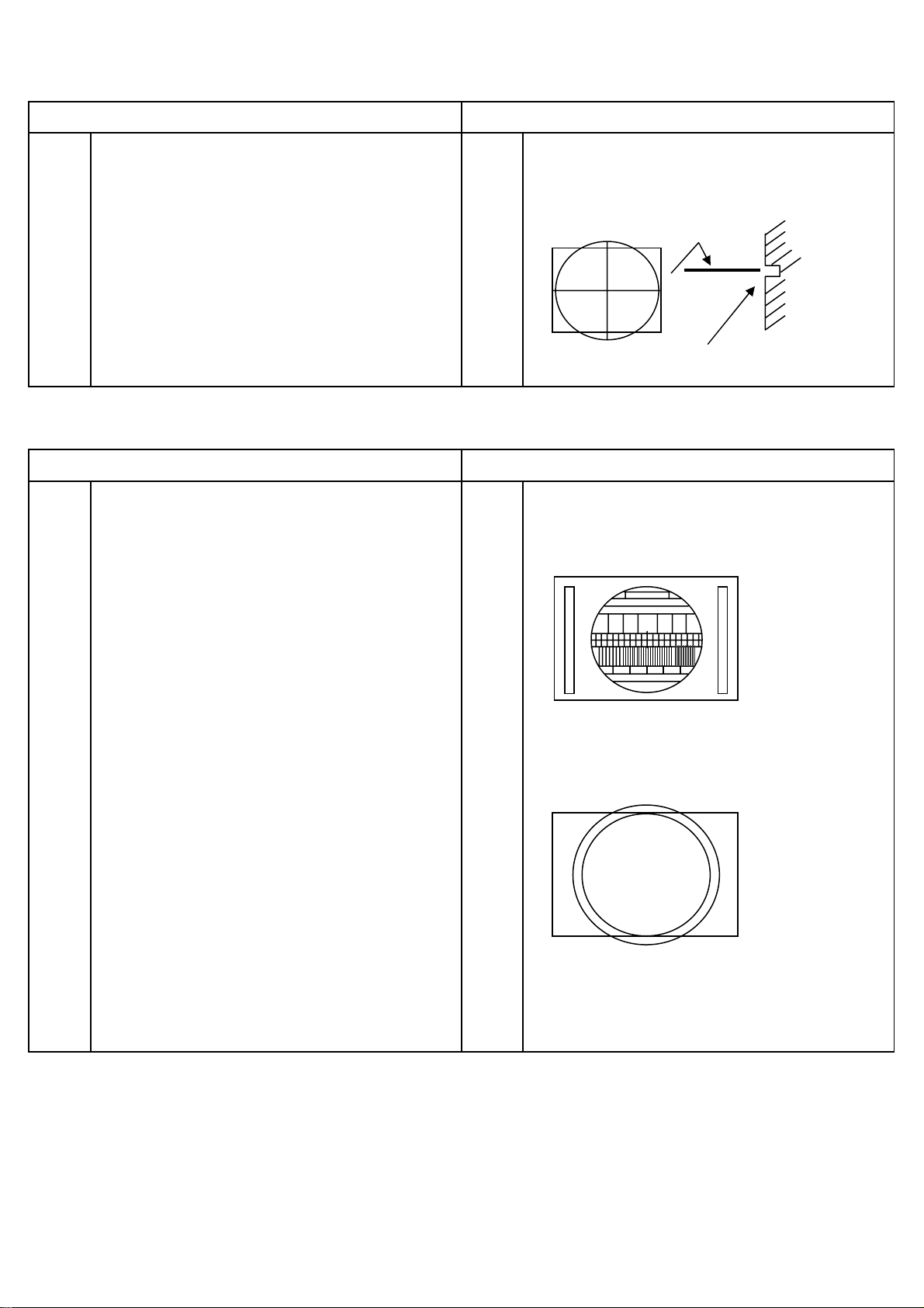
WHITE PEAK LEVEL ADJUSTMENT
PREPARATION PROCEDURES
1 Connect oscilloscope probe to pin 3 of E202 on CPT 1 Adjust output level at pin 3 of E202 as indicated below
P.W.B with respect to ground. using service mode no. 15.
2 Input PAL cross hatch signal to Video 2 terminal.
Cross hatch signal input level : 1 Vpp + 10%(with load
A
75 ohm) or 2 Vpp + 10%(no load).
3 Set CONTRAST to MAX.
1H
4 Set data in adjustment mode no.15 to 90. A = 2.8 + 0.1Vpp
- 7 -
VERTICAL SHIFT ADJUSTMENT
PREPARATION PROCEDURES
1 Preheat more than 5 minutes of power supply. 1 Select the IIC control address No. 11.
2 Receive PAL Philips pattern signal. 2 Set the horizontal center line to vertical center maker
of CRT by adjustment of IIC.
Vertical center marker of CRT
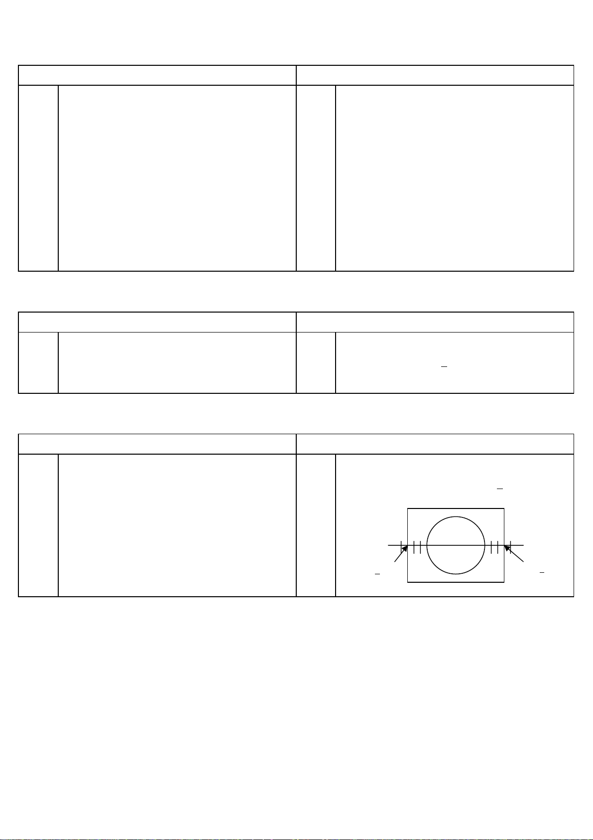
VERTICAL SIZE ADJUSTMENT
PREPARATION PROCEDURES
1 Preheat more than 5 minutes of power supply. 1 Select the IIC control address No. 12.
2 Receive Philips pattern signal. 2 Adjust IIC data to obtain the following conditions.
PAL
Check vertical amplitude as below by
3
NTSC circle pattern.
NTSC
4 If picture isn't center, go back to IIC control No. 11 and
adjust IIC data to obtain the following conditions.
- 8 -
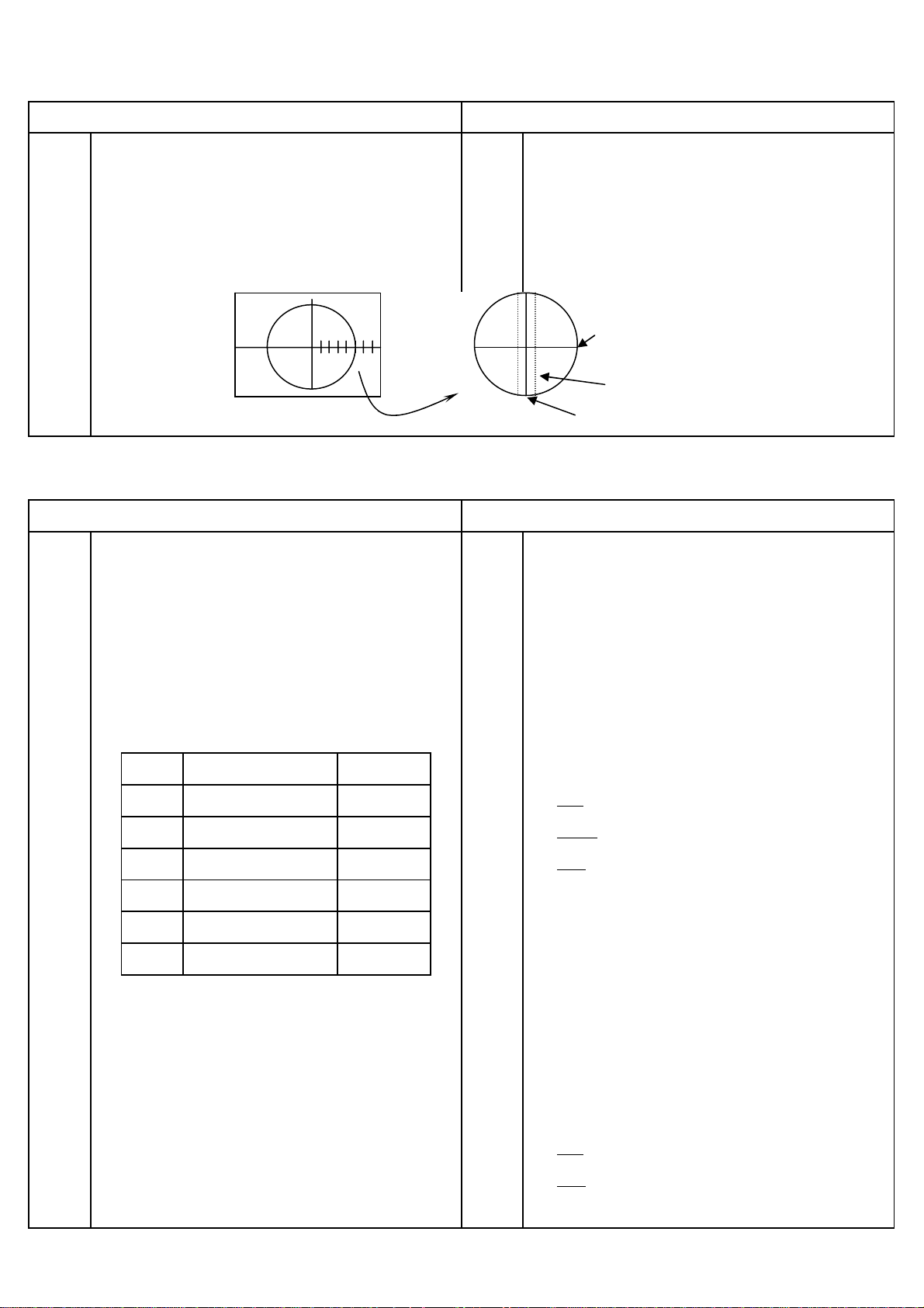
SIDE PIN DISTORTION ADJUSTMENT
PREPARATION PROCEDURES
Purity adjustment and convergence adjustment should
1
be already completed. 2
Set Contrast = 100, Brightness = 50
2
Set horizontal size adjustment to approximately 2-2 by
3
1 Receive the circle pattern signal.
st
Adjust the 1
outer vertical line (R/L) to pin, 2nd outer
vertical line (R/L) to straight using side pin adjustment
(PCC-AMP VR R557 / PCC-PHASE VR R564).
H-WIDTH VR R559. 3 Receive the cross hatch signal.
Vertical amplitude adjustment should be already
4
4 Check that the vertical line is straight, except 1st outer
completed. vertical line (R/L).
*Pin distortion spec. DL ≤ 3mm ,DR ≤ 2mm*
HORIZONTAL CENTER ADJUSTMENT
PREPARATION PROCEDURES
1 Side pin adjustment should be already completed. 1 Adjust adjustment mode no. 13 so that the average
2 Receive circle pattern signal. reading of R and L is 2.0 +
HORIZONTAL SIZE ADJUSTMENT
PREPARATION PROCEDURES
Horizontal center adjustment should be already
1
1 Adjust Horizontal size (H-WIDTH VR R559) so that the
completed. average reading of right and left is 2.0 +
2 Receive circle pattern signal.
3 Set Contrast = 100, Brightness = 50
2.0 + 0.5
0.5 at circle pattern signal.
0.5.
2.0 + 0.5
- 9 -
FOCUS ADJUSTMENT
s
A
PREPARATION
PROCEDURES
1 Receive Philips pattern signal. 1 Set picture to mode 1
2 Vertical amplitude adjustment should be already 2 Turn the focus VR gradually clockwise from the full
completed. counterclockwise and adjust so that the halo of vertical
3 Adjust the cut-off after pre-adjust focus VR. center line does not appear, and horizontal line is
4 Check the cut-off in case focus is re-adjusted MIN. width.
HORIZONTAL
1 2 3 4 5 6 7
NO.5
ZOOM
HALO
VERTICAL
WHITE BALANCE ADJUSTMENT
PREPARATION
1 Adjust the W/B after the Power is turned ON for 20 minute
1 Turn the screen adjusting VR clockwise and set it to the
PROCEDURES
2 Purity adjustment should be completed. position where the bright line starts appearing on CPT
3 Set the vertical incident illumination on the CPT surface screen.
to 20 lux or less. 2 Take the first appeared color as the reference. Adjust the
4 Receive white raster signal. other colors by remote until both appear to be the same
5 Set adjustment mode data as table on the next page level as the reference. (A white horizontal line is seen at
to default.
Disp No ITEM Default
016
017
018
019
020
021
R-CUTOFF
G-CUTOFF
B-CUTOFF
R-DRIVE
B-DRIVE
SUB-BRIGHT
127
127
127
63
63
127
6 Turn the screen adjustment VR fully counterclockwise. 5
7 Set to lateral line mode by Press “MUTE” button on
the CPT center.)
Low brightness adjustment data
Red
Green
Blue
………. ”1” key for up, “4” key for down.
………. ”2” key for up, “5” key for down.
………. ”3” key for up, “6” key for down
Don’t change the data of the reference color
3 Exit the lateral line mode. (Press “MUTE” by remote).
4 Set white balance meter at the center of the screen.
djust brightness control so that the indication of the
brightness meter is a prescribed value of brightness
remote control . adjustment. Adjust white balance with the white balance
control data (Red/Blue).
High brightness adjustment data
Red
Blue
………. ”7” key for up, “0” key for down.
………. ”8” key for up, “9” key for down.
- 10 -
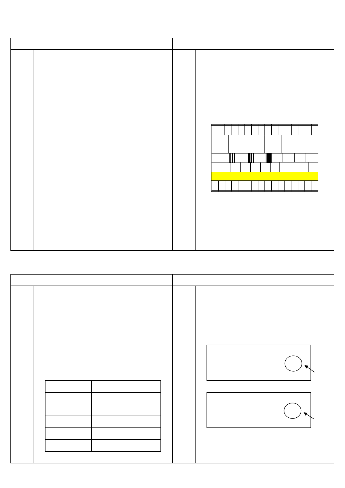
SUB-BRIGHTNESS ADJUSTMENT
A
A
PREPARATION PROCEDURES
1 Turn the TV set on and heat run for 20 minutes or more. 1 Press "PICTURE" key until go to picture mode 2.
2 Horizontal size adjustment and side pin adjustment 2 The sub-brightness should be adjusted (Adjustment
should be completed. mode no. 21) using11 steps gray scale (A1-A1) of color
3 Receive Philips pattern signal. bar pattern
Set picture mode 2 as shown below. 3 Adjust until A10 is complete black and A9 is lightly black.
4 Go out from service mode.
CONTRAST : 0
COLOR : 0
BRIGHTNESS : 50
A
11
A10A
A8A7A6A5A4A3A2A
9
1
5 Adjust picture mode 2 as below.
CONTRAST : 100
COLOR : 60
BRIGHTNESS : 50
6 Press "PICTURE" key until go to picture mode 1.
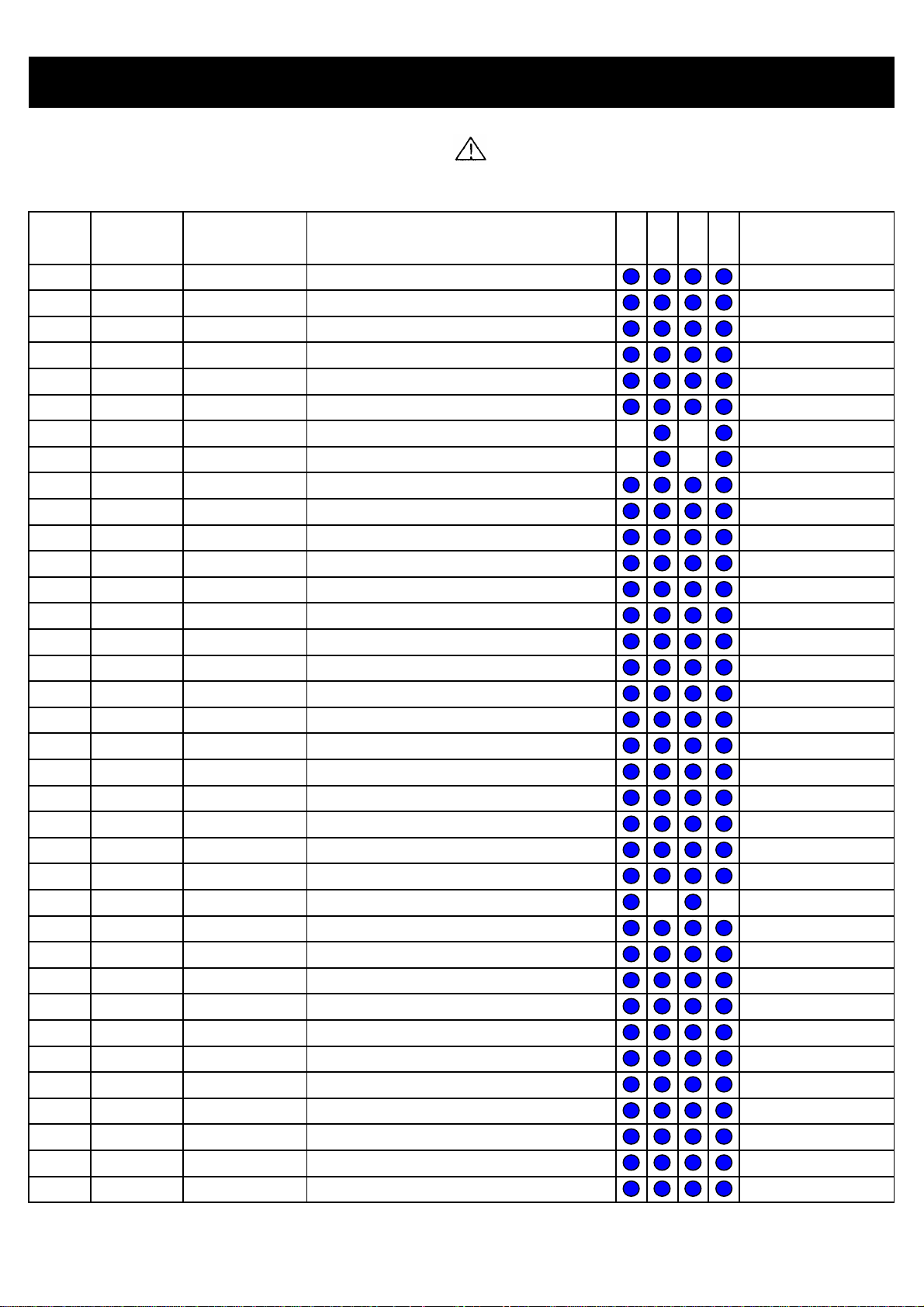
AGC ADJUSTMENT
PREPARATION PROCEDURES
1 All adjustment except for AGC adjustment should be 1 Select adjustment mode no. 14 (TUNER AGC) and press
completed. Heat-run for more than 5 min. “MENU” key one time. Data will be adjusted automatically
2 Receive signal as table on the next page. 2 .When AGC adjustment is complete,screen should be
3 Set Contrast = 100, Brightness = 50. shown "OK" on the right-top side. It the screen show
4 Set the Sound System and Color System depending on "NG" ,it means AGC adjustment is abnormal.
the broadcast system.
5 Set the antenna input level as specified below.
NO.
014 43 OK
DJUSTMENT 10
"OK"
MODEL T1
DESTINATION ALL
BGSYSTEM
CHANNEL CH10
INPUT SIGNAL Philips Pattern
INPUT LEVEL - 54 dBm / 55dBµ(75Ω)
NO.
014 15 NG
Caution : After AGC adjustment is complete, data in
adjustmentment mode no. 14 should be more than 30.
DJUSTMENT 10
"NG"
If not, please re-check or/and adjust again.
- 11 -

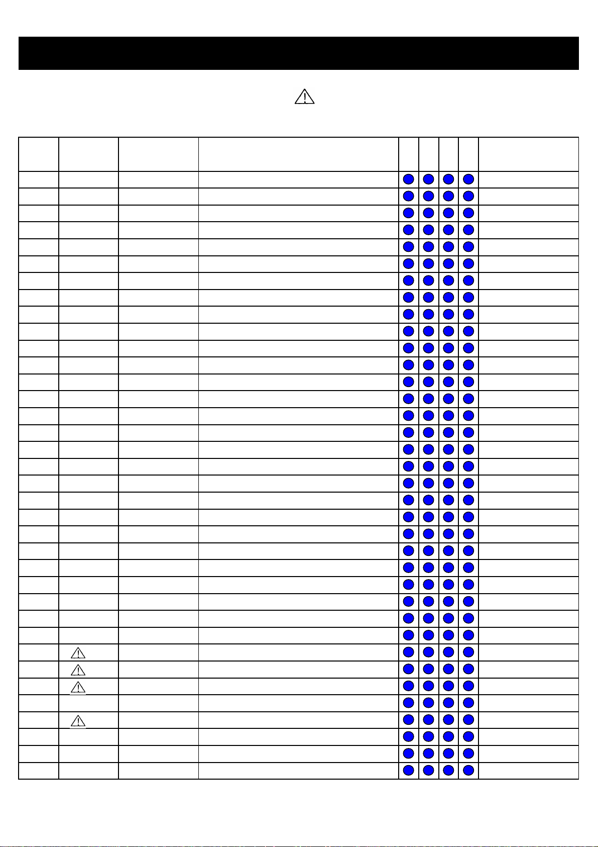
REPLACEMENT PARTS LIST
O
PRODUCT SAFETY NOTE : Components marked with a have special characteristics important to safety. Before
replacing any of these components, read carefully the PRODUCT SAFETY NOTICE of this Service Manual. Don't degrade
the safety of the receiver through improper servicing
NO CCT NO.
1
2
3
4
5
6
7
8
9
10
11
12
13
14
15
16
17
18
19
20
21
22
23
24
25
26
27
28
29
30
31
32
33
34
35
36
#I904
#I501
#Q502
#I901
#Q503
#D902
C101
C102
C103
C107
C108
C201
C202
C203
C206
C207
C208
C209
C210
C211
C212
C213
C214
C215
C216
C217
C218
C219
C220
C221
C222
C223
C224
C225
C226
C227
HITACHI HITACHI
PARTS NO. DESCRIPTION
THS0401001P
THS0402001P
THS0403001P
THS0404002P
THS0405001P
THS0405002P
0800358R
CE-1TZ103
0800294R
0800303R
0890092R
0800352R
CE-1TZ104
CE-1TZ104
CE-1TZ103
CE-1TCHJ181
CE-1TZ103
0800352R
0800279R
CE-1TZ103
0800279R
0800279R
0880183R
CE-1TCHJ221
CE-1TZ104
0800352R
0800317R
EL-B10V471R
0800362F
0890092R
0800279R
0890065R
0800277R
0880198R
0880198R
CE-1TZ104
HEAT SINK I904 / I905
HEAT SINK I501
HEAT SINK Q502
HEAT SINK I901 ( L = 60mm )
HEAT SINK Q503 ( L = 40mm )
HEAT SINK D902 ( L = 25mm )
CAP ELEC 1000UF 6.3V M
CAP CER 0.01UF 50V Z
CAP ELEC 10UF 50V M
CAP ELEC 22UF 50V M
CAP CER 2200PF 50V M
CAP ELEC 470UF 10V M
CAP CER 0.1UF 50V Z
CAP CER 0.1UF 50V Z
CAP CER 0.01UF 50V Z
CAP CER 180PF 50V J CH
CAP CER 0.01UF 50V Z
CAP ELEC 470UF 10V M
CAP ELEC 1UF 50V M
CAP CER 0.01UF 50V Z
CAP ELEC 1UF 50V M
CAP ELEC 1UF 50V M
CAP POLYESTER 0.015UF 50V J
CAP CER 220PF 50V J CH
CAP CER 0.1UF 50V Z
CAP ELEC 470UF 10V M
CAP ELEC 47UF 16V M
CAP ELEC 470UF 10V M 105
CAP ELEC 1000UF 25V M
CAP CER 2200PF 50V M
CAP ELEC 1UF 50V M
CAP CER 22PF 50V J SL
CAP ELEC 0.47UF 50V M
CAP POLYESTER 0.22UF 50V J
CAP POLYESTER 0.22UF 50V J
CAP CER 0.1UF 50V Z
SN ST SNT S
REMARK
C
- 12 -
REPLACEMENT PARTS LIST
O
O
PRODUCT SAFETY NOTE : Components marked with a have special characteristics important to safety. Before
replacing any of these components, read carefully the PRODUCT SAFETY NOTICE of this Service Manual. Don't degrade
the safety of the receiver through improper servicing
NO CCT NO.
37
38
39
40
41
42
43
44
45
46
47
48
49
50
51
52
53
54
55
56
57
58
59
60
61
62
63
64
65
66
67
68
69
70
71
72
C228
C229
C232
C233
C234
C236
C237
C238
C239
C241
C242
C243
C244
C245
C247
C248
C249
C250
C251
C252
C253
C255
C256
C257
C258
C401
C402
C403
C404
C405
C406
C407
C408
C409
C410
C411
HITACHI HITACHI
PARTS NO. DESCRIPTION
0880198R
0880181R
0890093R
0880194R
0800279R
CE-1TZ103
0890074R
0890074R
AL00002R
0800279R
0880207R
CE-1TZ103
CE-1TZ103
0800326R
0800279R
0880184R
CE-1TZ103
0800326R
EL-B16V101R
0800294R
EL-B50V100R
0800326R
CE-1TZ103
CE-1TZ103
CE-1TCHJ181
0800326R
0800277R
0800277R
0800294R
CE-1TZ103
0800294R
0800277R
0800277R
CE-1TZ103
0800294R
0800294R
CAP POLYESTER 0.22UF 50V J
CAP POLYESTER 0.01UF 50V J
CAP CER 2700PF 50V M
CAP POLYESTER 0.1UF 50V J
CAP ELEC 1UF 50V M
CAP CER 0.01UF 50V Z
CAP CER 100PF 50V J SL
CAP CER 100PF 50V J SL
CAP ELEC 1UF 160V M
CAP ELEC 1UF 50V M
CAP POLYESTER 1UF 50V J
CAP CER 0.01UF 50V Z
CAP CER 0.01UF 50V Z
CAP ELEC 100UF 16V M
CAP ELEC 1UF 50V M
CAP POLYESTER 0.018UF 50V J
CAP CER 0.01UF 50V Z
CAP ELEC 100UF 16V M
CAP ELEC 100UF 16V M 105
CAP ELEC 10UF 50V M
CAP ELEC 10UF 50V M 105
CAP ELEC 100UF 16V M
CAP CER 0.01UF 50V Z
CAP CER 0.01UF 50V Z
CAP CER 180PF 50V J CH
CAP ELEC 100UF 16V M
CAP ELEC 0.47UF 50V M
CAP ELEC 0.47UF 50V M
CAP ELEC 10UF 50V M
CAP CER 0.01UF 50V Z
CAP ELEC 10UF 50V M
CAP ELEC 0.47UF 50V M
CAP ELEC 0.47UF 50V M
CAP CER 0.01UF 50V Z
CAP ELEC 10UF 50V M
CAP ELEC 10UF 50V M
SN ST SNT S
REMARK
C
C
- 13 -
REPLACEMENT PARTS LIST
O
PRODUCT SAFETY NOTE : Components marked with a have special characteristics important to safety. Before
replacing any of these components, read carefully the PRODUCT SAFETY NOTICE of this Service Manual. Don't degrade
the safety of the receiver through improper servicing
NO CCT NO.
73
74
75
76
77
78
79
80
81
82
83
84
85
86
87
88
89
90
91
92
93
94
95
96
97
98
99
100
101
102
103
104
105
106
107
108
C412
C413
C414
C415
C416
C417
C418
C431
C432
C433
C436
C437
C451
C501
C501A
C502
C504
C505
C506
C507
C509
C510
C511
C515
C516
C517
C518
C519
C520
C521
C522
C524
C525
C526
C527
C701
HITACHI HITACHI
PARTS NO. DESCRIPTION
0800277R
0800294R
0800294R
0800294R
0800277R
CE-1TZ103
0800352R
0800294R
0800294R
0800294R
0800294R
0800294R
0800277R
0279693R
0279693R
0800328R
0800368F
0880209R
0800355R
0800354R
AL00028R
0880204R
0800355R
0299622F
0284642R
0243510R
0243503R
EL-B160V010R
0262427F
0299987F
0262423F
CM-50V3U3J
AN01177F
0890074R
0279690R
0800315R
CAP ELEC 0.47UF 50V M
CAP ELEC 10UF 50V M
CAP ELEC 10UF 50V M
CAP ELEC 10UF 50V M
CAP ELEC 0.47UF 50V M
CAP CER 0.01UF 50V Z
CAP ELEC 470UF 10V M
CAP ELEC 10UF 50V M
CAP ELEC 10UF 50V M
CAP ELEC 10UF 50V M
CAP ELEC 10UF 50V M
CAP ELEC 10UF 50V M
CAP ELEC 0.47UF 50V M
CAP POLY FILM 0.1UF 100V K
CAP POLY FILM 0.1UF 100V K
CAP ELEC 100UF 35V M
CAP ELEC 2200UF 25V M
CAP POLYESTER 1.5UF 50V J
CAP ELEC 470UF 35V M
CAP ELEC 470UF 25V M
CAP ELEC 10UF 250V M
CAP POLYESTER 0.56UF 50V J
CAP ELEC 470UF 35V M
CAP POLYPROPY 0.01UF 630V J
CAP ELEC 50V 10 UF (NP)
CAP CER 560PF 500V K
CAP CER 150PF 500V K
CAP ELEC 1UF 160V M 105
CAP M-POLYPRO 0.01UF J 1.8KHP
CAP POLYPRO 0.039UF J 630V
CAP M-POLYPRO 6800PF J 1.8KHP
CAP POLYESTER 3.3UF 50V J
CAP M-POLYPRO 0.43UF J 250V
CAP CER 100PF 50V J
CAP POLYESTER 0.033UF 100V K
CAP ELEC 47UF 6.3V
SN ST SNT S
REMARK
C
- 14 -

REPLACEMENT PARTS LIST
o
o
o
o
o
o
PRODUCT SAFETY NOTE : Components marked with a have special characteristics important to safety. Before
replacing any of these components, read carefully the PRODUCT SAFETY NOTICE of this Service Manual. Don't degrade
the safety of the receiver through improper servicing
NO CCT NO.
109
110
111
112
113
114
115
116
117
118
119
120
121
122
123
124
125
126
127
128
129
130
131
132
133
134
135
136
137
138
139
140
141
142
143
144
C701A
C702
C703
C704
C705
C711
C712
C713
C714
C716
C902
C903
C904
C905
C906
C907
C908
C909
C910
C911
C912
C913
C914
C915
C916
C917
C919
C921
C923
C924
C924
C928
C929
C930
C931
C932
HITACHI HITACHI
PARTS NO. DESCRIPTION
0880057R
0800326R
CE-1TZ103
0890083R
CE-1TZ103
CE-1TZ103
CE-1TZ103
0800326R
0890087R
0800294R
0880035R
EL-B35V470R
0880038R
EL-B50V010R
0880038R
EL-B50V010R
EL-B50V100R
CE-1TZ104
EL-B25V222R
0880194R
0880194R
0880194R
0880194R
EL-B25V102R
AL01663
0800294R
AJ00542F
0890087R
CE-1TCHJ181
0800348R
CE-1TZ104
AJ00454F
0890083R
0800294R
AL01702
AN02083S
CAP POLYESTER 0.1UF 50V K
CAP ELEC 100UF 16V M
CAP CER 0.01UF 50V Z
CAP CER 470PF 50V K
CAP CER 0.01UF 50V Z
CAP CER 0.01UF 50V Z
CAP CER 0.01UF 50V Z
CAP ELEC 100UF 16V M
CAP CER 1000PF 50V K
CAP ELEC 10UF 50V M
CAP POLYESTER 2200PF 50V K
CAP ELEC 47UF 35V M 105
CAP POLYESTER 3900PF 50V K
CAP ELEC 1UF 50V M 105
CAP POLYESTER 3900PF 50V K
CAP ELEC 1UF 50V M 105
CAP ELEC 10UF 50V M 105
CAP CER 0.1UF 50V Z
CAP ELEC 2200UF 25V M 105
CAP POLYESTER 0.1UF 50V J
CAP POLYESTER 0.1UF 50V J
CAP POLYESTER 0.1UF 50V J
CAP POLYESTER 0.1UF 50V J
CAP ELEC 1000UF 25V M 105
CAP ELEC 330UF 160V M
CAP ELEC 10UF 50V M
CAP CER 4700PF 1KV K
CAP CER 1000PF 50V K
CAP CER 180PF 50V J CH
CAP ELEC 330UF 63V M
CAP CER 0.1UF 50V Z
CAP CER 1000PF 1KV K
CAP CER 470PF 50V K
CAP ELEC 10UF 50V M
CAP ELEC 220UF 450V M
CAP M-POLYPRO X2 0.1UF K 250V
SN ST SNT S
REMARK
C
C
C
C
C
C
Code 433, 435 only
- 15 -
 Loading...